page 4
MEASURING
1. Visually note a unique feature on the
object to be measured or physically
mark it with reflective tape or chalk.
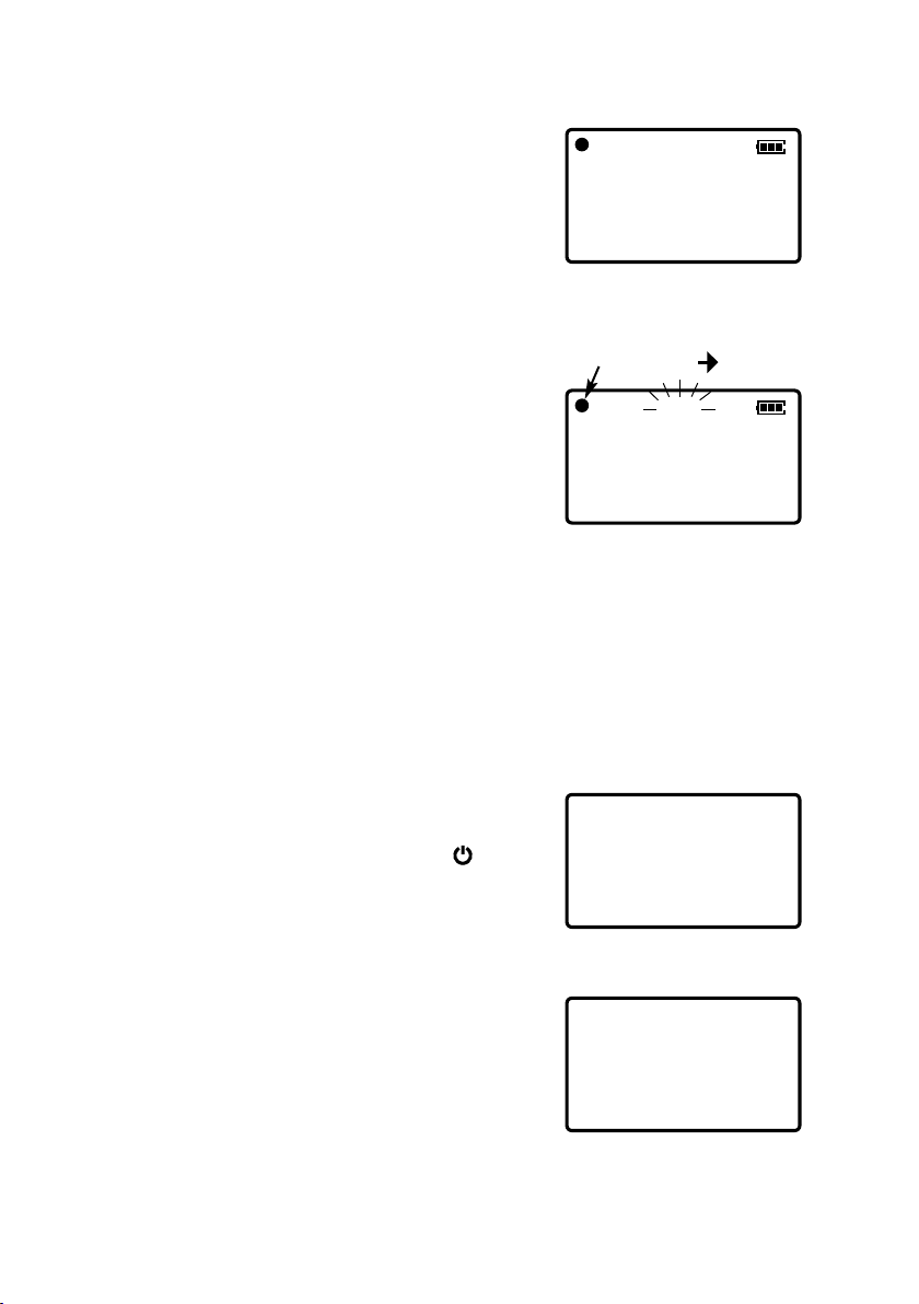
2. Press to turn on the strobe. The
LED indicator blinks and the strobe
flashes at 3,000 FPM factory default
or previous power down value.
3. Set flash rate to maximum and aim
at the object. Press the ▼arrow until
the object appears frozen. To find true
rpm, press the ÷2 button, ▲or ▼
arrows, to adjust the flash rate until
the first time a single mark appears.
The flash rate changes more rapidly the longer the ▲or ▼arrow key is
held, then resets 1.5 seconds after it is released.
Advanced users: After releasing the ▲or ▼arrow, the numeric place of
the flashing digit indicates the rate of change. While the digit is flashing,
press the or arrows to move the numeric place of the flashing digit
higher or lower. Then press the ▲or ▼arrow to change the flash rate
using that increment.
4. Press to turn off the strobe (the display remains for two more
minutes). The strobe shuts off automatically after 10 minutes.
▲
▲
PREPARATION
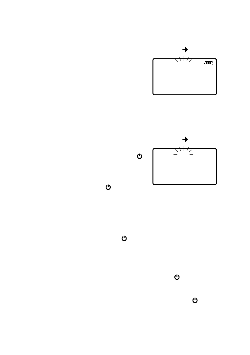
Changing Units (FPM is the factory default)
Turn off the strobe (the strobe light goes off
and the display stays on for two more minutes).
Press and hold MODE, then press the power
switch and SEL is displayed. Press the or
arrows to select FPM or Hz. The selected
unit becomes the default when the strobe is
powered on. Press the power switch to exit.
▲
▲
–SEL–
FPM
F0
Changing Image Position
After synchronizing the flash rate with the moving object, press –or +
to adjust the position or angle.
NOTE: IF THE FLASH RATE
IS 1/2 OF TRUE RPM, 1/3,
1/4, ETC., A SINGLE MARK
ALSO APPEARS.
IF THE FLASH RATE IS 2X
TRUE RPM, TWO MARKS
APPEAR, 3X TRUE RPM,
THREE MARKS, 4X, FOUR
MARKS, ETC.
IF THE FLASH RATE IS 2/3
OF TRUE RPM, 2/5, 2/7
ETC., TWO MARKS
APPEAR. AND 4/3, 4/5
AND 4/7 FOUR MARKS
APPEAR, ETC.
FPM, FLASHES PER MINUTE IS BEST
FOR MOST APPLICATIONS.
HZ IS FLASHES PER SECOND.
SELECT WITH LEFT/RIGHT ARROWS
RECHARGING THE BATTERY
IMPORTANT! Use the provided AC adapter/
charger exclusively and plug into the correct AC
output; others will cause damage.
When the Battery icon appears on the display,
turn off the unit and connect to the AC
adapter/charger.
CHG is displayed and the LED indicator light
flashes and turns solid as the unit is charged.
– – – – – appears when charging is complete
and the LED indicator turns off.
The strobe requires eight hours for a complete
recharge.
If another charger is used either AC-HI or AC-
LO errors may be displayed.
3000.0
FPM
LOW BATT
F0
–chg–
–––––
CHARGING COMPLETE
CHARGING
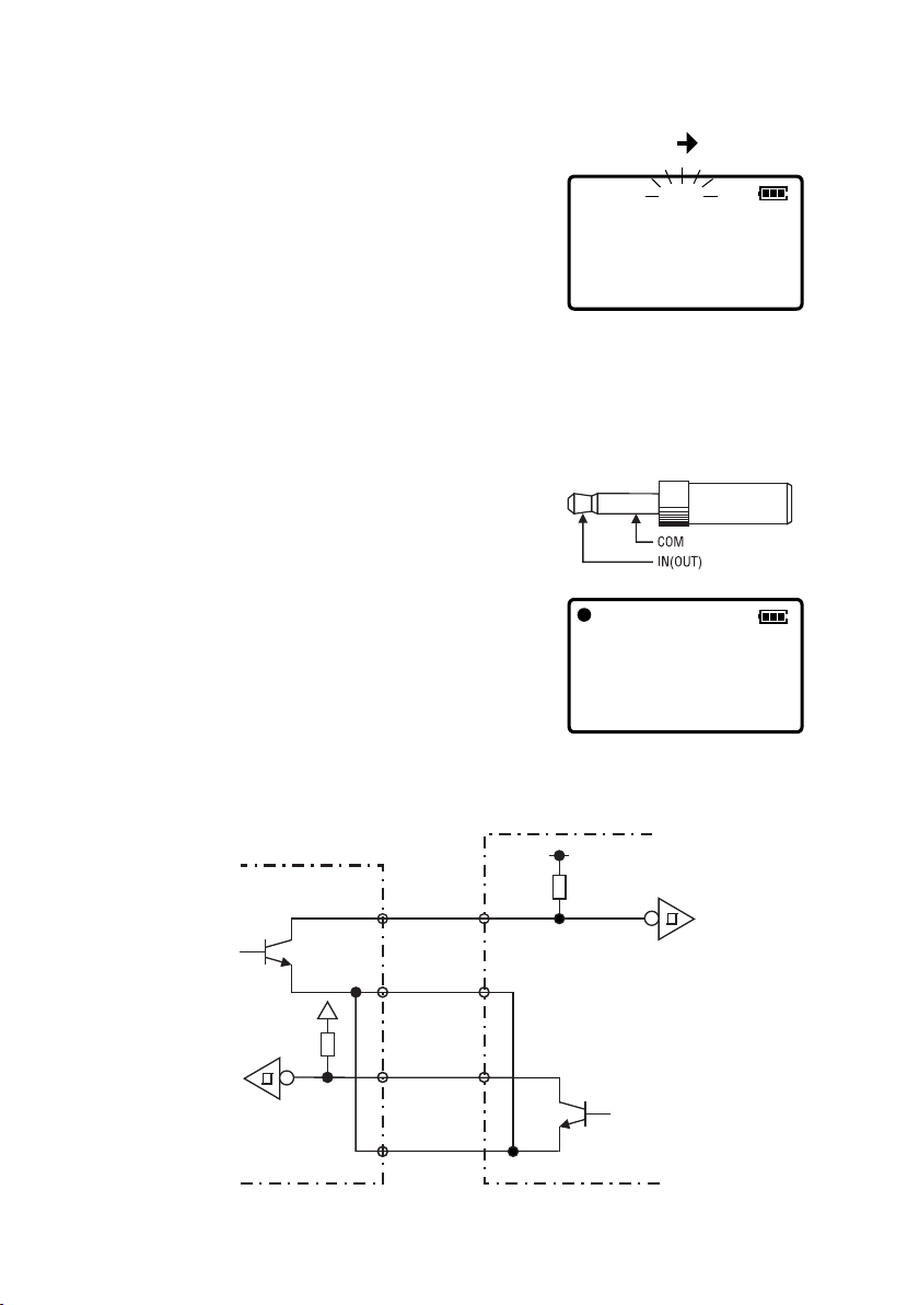
Digital Phase Shift (Only w/ external trigger)
The input signal’s cycle is 360°. Press the
phase –and +keys to view the delayed angle
of the input cycle. The range of this adjustment
(phase shift) is 0 to 359°. The angle appears
on the display when the –and +keys are
pressed and three seconds after they are
released the display returns to flashes per
minute, while maintaining the phase shift
setting. The black dot appears when the
position has been changed from the original.
Press and hold MODE while pressing –and +
keys to shift in 45° increments. When the
instrument is turned off, the phase shift
setting remains in memory.
3000.0
FPM
EXT
F0
2
deg
EXT
F0
VALUE AND ANGLE TOGGLE
DURING PHASE SHIFT
EXTERNAL TRIGGER MODE ONLY
BLACK DOT APPEARS WHEN
POSITION HAS BEEN CHANGED
FROM THE ORIGINAL