7. CHARGING THE INTERNAL BATTERY OF THE BOOSTER
• Press the Voltmeter button to show the
charge level of the battery.
•After starting the engine at 2000 rpm,
leave the booster connected to the
vehicle and press the voltmeter button.
The voltmeter will indicate between
14 and 14,4 volts (at 2000 rpm) if the
alternator is functioning correctly.
7.1 Grounding and AC Power Cord
Connections
IMPORTANT. Only use the charger that
was included with the booster to charge
the internal battery of the booster. Using a
different charger could result in personal
injury or property damage.
WARNING!
RISK OF ELECTRIC SHOCK OR FIRE.
This battery charger is for use on a
nominal 120V circuit. The plug must be
plugged into an outlet that is properly
installed in accordance with all local
codes and ordinances. The plug pins
must t the receptacle (outlet). Do not use
with an ungrounded system.
DANGER. Never alter the AC cord or plug
provided – if it does not t the outlet, have
a proper outlet installed by a qualied
electrician. An improper connection can
result in a risk of an electric shock or
electrocution.
An extension cord should not be used
unless absolutely necessary. Use of an
improper extension cord could result
in a risk of re and electric shock. If an
extension cord must be used, make sure:
• That the pins on the plug of the extension
cord are the same number, size and
shape as those of the plug on the
charger.
• That the extension cord is properly wired
and in good electrical condition.
• That the wire size is large enough for the
AC ampere rating of the charger,
as specied:
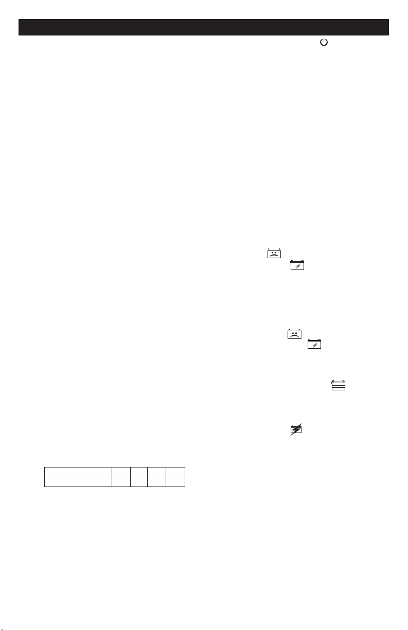
Length of cord (feet) 25 50 100 150
AWG* size of cord 18 18 18 16
*AWG-American Wire Gauge
7.2 Charging the Booster
1. Connect the end of the charger quick-
connect to the charger.
2. Insert the charge plug into the charge
port on the back of the booster.
3. Plug the charger’s power cord into
a grounded 120V AC electrical wall
outlet.
4. The charger’s green POWER LED
will light.
5. Charging will begin within ten minutes
and nish automatically. (Press the
Start/Stop button to begin charging
immediately.)
6. The pulsing green LED indicates the
battery is fully charged.
7. When charging is complete,
disconnect the charger from the AC
power. Then remove the charging plug
from the booster.
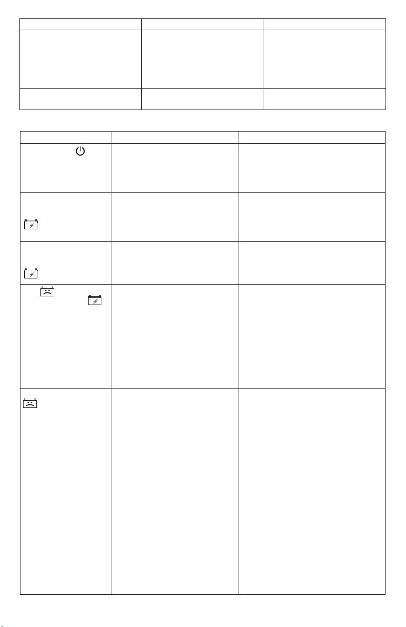
7.3 Charger Modes
Automatic charging mode
When an automatic charge is performed,
the charger switches to maintain mode
automatically after the battery is charged.
Aborted Charge
If charging cannot be completed normally,
charging will abort. When charging aborts,
the charger’s output is shut off. The BAD
BATTERY (red) LED will light, and
the CHARGING (yellow/orange) LED
will ash. Do not continue attempting to
charge this battery. Check the battery and
replace, if necessary.
Desulfation Mode
Desulfation could take 8 to 10 hours. If
desulfation fails, charging will abort. The
BAD BATTERY (red) LED will light,
and the CHARGING (yellow/orange)
LED will ash.
Completion of Charge
Charge completion is indicated by the
CHARGED/MAINTAINING (green)
LED. When pulsing, the charger has
switched to Maintain Mode.
Maintain Mode (Float-Mode Monitoring)
When the green (CHARGED) LED is
pulsing, the charger has started maintain
mode. In this mode, the charger keeps the
battery fully charged by delivering a small
current when necessary. If the charger
has to provide its maximum maintain
current for a continuous 12 hour period,
it will go into abort mode (see Aborted
Charge). This is usually caused by a
drain on the battery or the battery could
be bad. Make sure there are no loads on
the battery. If there are, remove them. If
there are none, have the battery checked
or replaced.