manuals.online logo
Brands
  1. Home
  2. •
  3. Brands
  4. •
  5. Schwank
  6. •
  7. Heater
  8. •
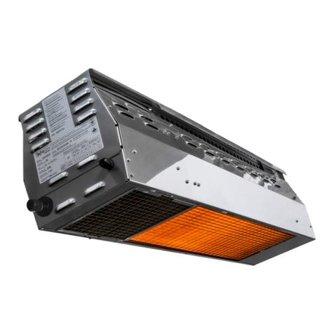
  9. Schwank SST-MX Series Instruction Manual

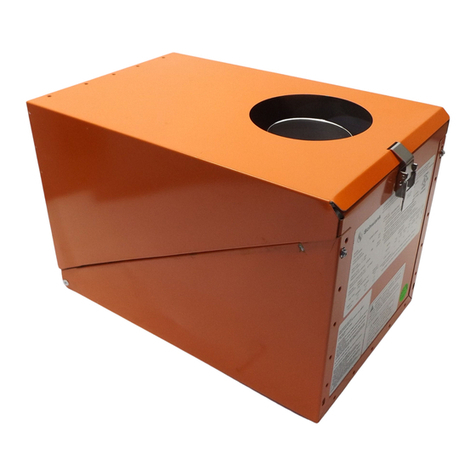
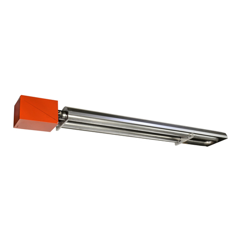
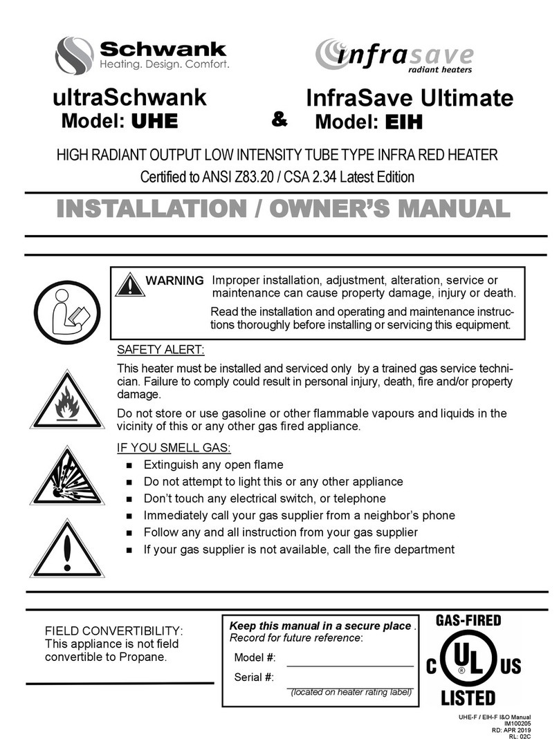
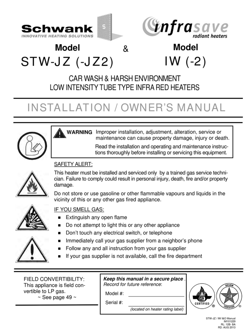
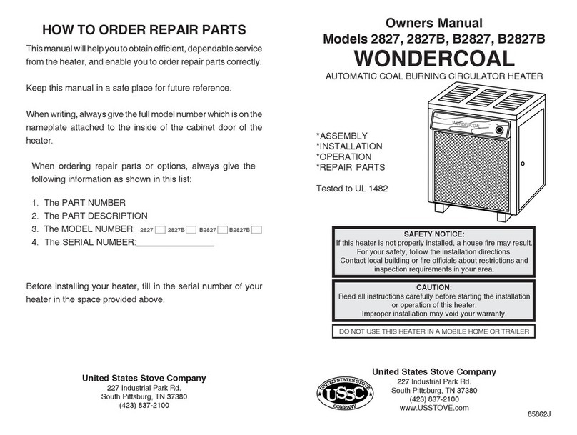
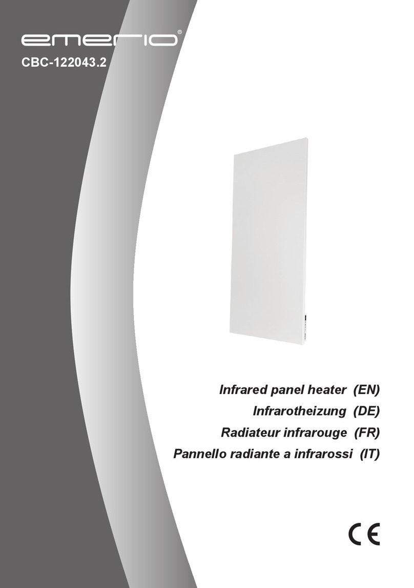
Schwank SST-MX Series Instruction Manual

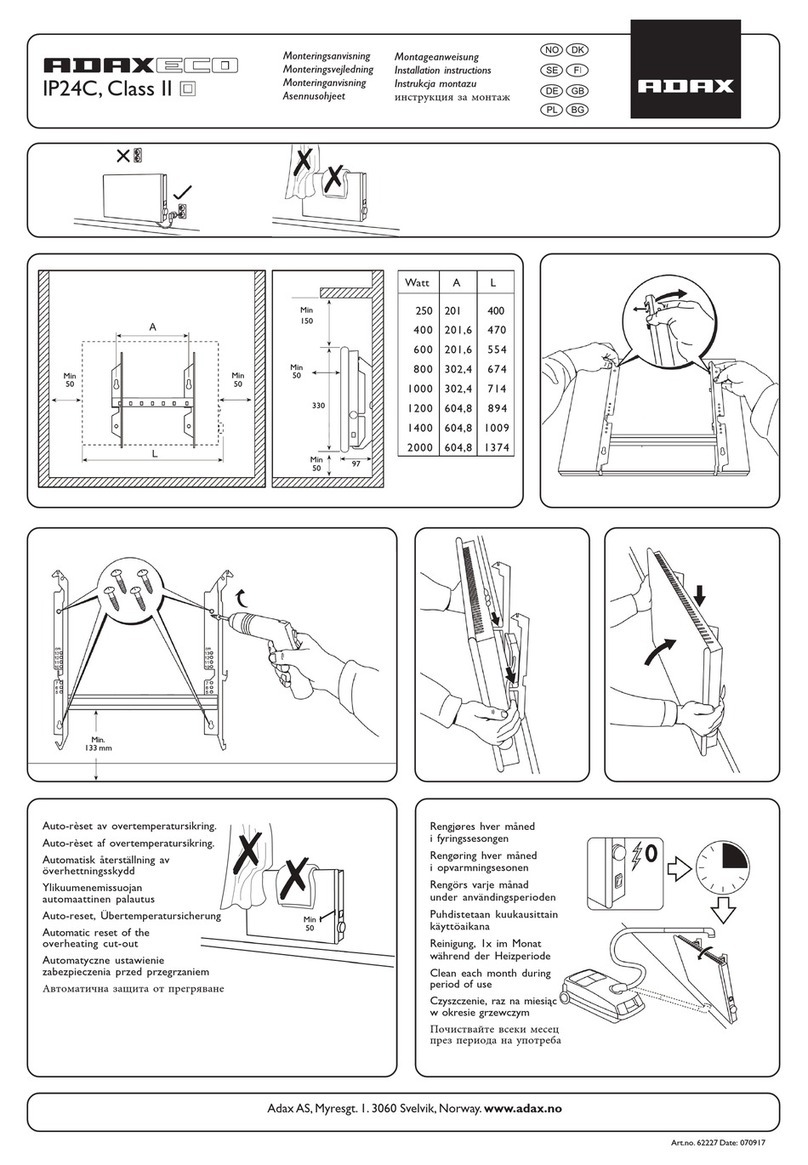
SST Extreme X & SST Extreme S MODULATING I&O Manual
RD: JAN 2021
RL: 1A
MODULATING —SUPPLEMENTARY MANUAL
A GENERAL INFORMATION MANUAL IS INCLUDED IN THE BURNER KIT
SAFETY ALERT:
Do not store or use gasoline or other flammable vapours and liquids in the vicinity of
this or any other gas fired appliance.
IF YOU SMELL GAS:
◼ Extinguish any open flame
◼ Do not attempt to light this or any other appliance
◼ Don’t touch any electrical switch, or telephone
◼ Immediately call your gas supplier from a neighbor’s phone
◼ Follow any and all instruction from your gas supplier
◼ If your gas supplier is not available, call the fire department

FIELD CONVERTIBILITY:
This appliance is field convertible to LP gas.
Only use a kit available from manufacturer.
Follow instructions provided in the kit and all local
and national codes.
Keep this manual in a secure place .
Record for future reference:
Model #:
Serial #:
(located on heater rating label)
OUTDOOR,CAR WASH & WET ENVIRONMENT
LOW INTENSITY TUBE TYPE INFRARED HEATER
WITH HIGH EFFICIENCY EC Motors
Improper installation, adjustment, alteration, service or maintenance
can cause property damage, injury or death. Read the installation, op-
erating and maintenance instructions thoroughly before installing or
servicing this heater.
superTube Extreme Heaters
SST-MX / SST-MS SERIES
ANSI Z83.20-2016 • CSA 2.34-2016
ANSI Z83.26:20• CSA 2.37:20
2
SST Extreme X & SST Extreme S MODULATING I&O Manual
RD: JAN 2022
RL: 1A
NOTICE:
This manual is current and correct for this product at time of manufacture. Occasional revision
of the product and/or Certification Standard may require changes to the product and/or this
manual.
This publication, or parts thereof, may not be reproduced in any form, without prior written con-
sent from The Manufacturer. Unauthorized use or distribution of this publication is strictly pro-
hibited.
Schwank Ltd
Schwank
5285 Bradco Boulevard
Mississauga, Ontario,L4W 2A6
2 Schwank Way
Waynesboro, Georgia 30830
Customer & Technical Services
Phone: 877-446-3727
Fax: 866-361-0523
e-mail:
[email protected]
www.schwankgroup.com
3
SST Extreme X & SST Extreme S MODULATING I&O Manual
RD: JAN 2021
RL: 1A

 ..... 
 4
1. INPUT RATINGS AND DIMENSIONS 5
2. BURNER / TUBE KIT ASSEMBLY CHART 7
3. TURBULATOR LENGTH & LOCATION 8
4. COMBUSTION AIR DUCTING 11
5. FLUE VENTING: 12
MIN./MAX. SYSTEM LENGTHS 13
HEATER EXPANSION & VENT 14
VERTICAL VENTING—CATEGORY I 15
HORIZONTAL VENTING—CATEGORY III 16
6. GAS SUPPLY PRESSURES 18
7. ELECTRICAL AND THERMOSTAT 18
8A. WIRING DIAGRAM: CHANNEL DSI
24V or 120V THERMOSTAT 19
……...
9. CHANNEL DSI: SEQUENCE OF OPERATION 23
SPARK IGNITER SET UP 25
CHANNEL DSI SERVICE CHECK 25
10. TROUBLESHOOTING GUIDE: DSI 26
11. TROUBLESHOOTING GUIDE: HEATER 27
12. START– UP / COMMISSIONING SHEET 29
13. GAS CONVERSION OF BURNER 31
14. HIGH ALTITUDE & ORIFICE CHART 32
15. BURNER PARTS LIST 33
16. TUBE SYSTEM PARTS LIST 36
--
• ALSO REFER TO THE GENERAL MANUAL INCLUDED FOR THIS SERIES HEATER

 ....... 
IMPORTANT INFORMATION - READ FIRST
 5
 6, 25
 6, 24
 6
‘’6
 6
‘’7
 7
Clearances Figure & Table 8
 9
1. LABOR REQUIREMENTS 10
2. INSTALLATION IN AIRCRAFT HANGARS 10
3. COMMERCIAL GARAGES 10
4. USE OTHER THAN SPACE HEATING 10
5. PRE-INSTALLATION SURVEY 11
6. MOUNTING CLEARANCES 12
SERVICE CLEARANCE 12
HEATER PLACEMENT GUIDELINES 13
……...
7. SYSTEMS WITH 90° & 180° ELBOWS 14
ELBOW KIT DIMENSIONS 15
8. SUSPENSION OF THE SYSTEM 16
9. BURNER & TUBE INSTALLATION:
STRAIGHT TUBE SYSTEM 18
SPECIAL COUPLING - 180 to 260 Mbh 21
10. SESMIC RESTRAINT 22
HIGH WIND RESTRAINT 22
11. REFLECTOR INSTALLATION 23
12. GAS SUPPLY 24
HEATER EXPANSION 25
FLEXIBLE GAS CONNECTION 26
13. ELECTRICAL AND THERMOSTAT 27
14. HIGH ALTITUDE INSTALLATION 27
15. LIGHTING INSTRUCTIONS 27
16. RECOMMENDED MAINTENANCE 27
17. OPTIONAL ACCESSORIES 28
OPTIONAL CONTROLS 30
WARRANTY STATEMENT BACK PAGE
4
SST Extreme X & SST Extreme S MODULATING I&O Manual
RD: JAN 2022
RL: 1A

--are modulating gas-fired radiant tube heatersthat may be in-
stalled for heating of commercial / industrial outdoor and indoor spaces.Not for use in residential
dwellings.
A “residential dwelling” is defined in the standard as “a housekeeping unit used or intended to be
used as a domicile by one or more persons, containing cooking, eating, living, sleeping, and/or
sanitary facilities. A residential dwelling does not include an attached garage, detached garage,
workshop or outdoors”. Local Code requirements take precedence for this application.
It is beyond the scope of these instructions to consider all conditions and requirements that may
be encountered in the field. Installation must conform with all local codes or, in the absence of
local codes, with the latest edition of the National Fuel Gas Code, ANSI Z223.1/NFPA 54 in the
U.S.A. or the Natural Gas and Propane Installation Code, CSA B149.1 in Canada. The latest edi-
tion Electrical Code ANSI/NFPA No. 70 in the U.S.A. and PART 1 CSA C22.1 in Canada must
also be observed.
Installation of a gas fired tube heater must conform to all heating installation design procedures
including clearance to combustibles, connection to the gas and electrical supplies, and ventilation
requirements.
This heater is not for installation in a Class 1 or Class 2 explosive environment, nor in a residen-
tial dwelling. If installation of this equipment is in question, consult with the local authority having
jurisdiction (Fire Marshall, labor department, insurance underwriter, or other).
Revisions to codes and/or standards, may require revision to equipment and installation proce-
dures. In case of discrepancy, the latest codes, standards, and installation manual will take priori-
ty over prior releases.
Improper installation, adjustment, alteration, service or maintenance can cause
property damage, injury or death. Read and understand this installation and op-
eration manual thoroughly prior to assembly, installation, operation or service to
this appliance.
This heater must be installed and serviced only by a trained gas service techni-
cian.
Do not store or use gasoline or other flammable vapours and liquids in the vicinity
of this or any other gas fired appliance.
Failure to comply could result in personal injury, death, fire and/or property dam-
age.
Do not store or use gasoline or other flammable vapours and liquids in the vicinity
of this or any other gas fired appliance.
This appliance may have sharp edges and corners. Wear protective clothing such
as gloves and protective eye wear when servicing this or any other appliance.

California Proposition 65:
: This product can expose you to chemicals including carbon monoxide, which
is known to the State of California to cause birth defects or other reproductive harm. For more
information, go to www.P65Warnings.ca.gov
5
SST Extreme X & SST Extreme S MODULATING I&O Manual
RD: JAN 2021
RL: 1A
--
 - 
205,000 or less:
JL-0771-XX - 1/2”x24”
225,000 or more:
JL-0771-YY - 3/4”x36”
FLEXIBLE GAS CONNECTOR (Included in Burner Kit) - MUST INSTALL - see GENERAL MANUAL Section 15
 - 
205,000 or less:
JL-0771-RC - 1/2”x30”
225,000 or more:
JL-0771-RB - 3/4”x30”
See next page for dimensions of heater components (Burner, tube, reflector, turn box)



 





80,000-60,000 NG / PROPANE
20 21’ 111
30 30' 9" 154
115,000-72,000 NG / PROPANE
30 30' 9" 154
40 40’ 5” 197
155,000-100,000 NG / PROPANE
40 40’ 5” 197
50 50’ 239
205,000-125,000 NG / PROPANE
50 50’ 7” 239
60 60' 3" 282
250,000-160,000 NG / PROPANE
60 60' 3" 282
70 69’ 11” 324
6
SST Extreme X & SST Extreme S MODULATING I&O Manual
RD: JAN 2022
RL: 1A
-
Tube
Length ‘’ = center air intake to end
10’ 11’-4 1/2” ; 136 1/2”
20’ 21’ ; 252”
30’ 30’-8 1/2” ; 368 1/2”
40’ 40’-4 1/2” ; 484 1/2”
Tube
Length ‘’ = center air intake to end
50’ 50’ ; 600”
60’ 59’-8 1/2” ; 716 1/2”
70’ 69’-3 1/2” ; 832 1/2”
80’ 79’ ; 948”
• POSITION BURNER END HANGER 4 INCHES FROM BURNER CONNECTION
• LOCATE SYSTEM HANGERS NO LESS THAN 6 INCHES AND NO MORE THAN 24 INCHES
FROM TUBE COUPLING

REFLECTOR = 120”
7
SST Extreme X & SST Extreme S MODULATING I&O Manual
RD: JAN 2021
RL: 1A
--

INPUT (BTUH) TUBE
LENGTH
BASE SYSTEM TUBE KIT(S)
FIRST TUBE










PRIMARY KIT SECONDARY
KIT
80,000-60,000 20 TH-P2PP-ST - Aluminized
Steel (3) x 2.25” x 36” No action re-
quired
80,000-60,000 30 TH-P3PP-ST - Aluminized
Steel (3) x 2.25” x 36” Remove 1 turbu-
lator from 2nd
115,000-72,000 30 TH-P3PP-ST - Aluminized
Steel (3) x 2.25” x 36” No action re-
quired
115,000-72,000 40 TH-P4PP-ST - Aluminized
Steel (3) x 2.25” x 36”
Remove 1 turbu-
lator from 4th
tube
155,000-100,000 40 TH-P4PP-ST - Aluminized
Steel (3) x 2.25” x 36” No action re-
quired
155,000-100,000 50 TH-P3PP-ST TH-S2PP-ST Aluminized
Steel (3) x 2.25” x 36”
Remove 1 turbu-
lator from 4th
tube
205,000-125,000 50 TH-P3PP-ST TH-S2PP-ST Aluminized
Steel (3) x 2.25” x 36” Remove 1 turbu-
lator from 5th
205,000-125,000 60 TH-P3PP-ST TH-S3PP-ST Aluminized
Steel (3) x 2.25” x 36”
Remove 2 turbu-
lator from 5th
tube
250,000-160,000 60 TH-P4SP-ST TH-S2PP-ST Stainless
Steel (1) x 2.25” x 36” No action re-
quired
250,000-160,000 70 TH-P4SP-ST TH-S3PP-ST Stainless
Steel (1) x 2.25” x 36”
Remove 1 turbu-
lator from 6th
tube
8
SST Extreme X & SST Extreme S MODULATING I&O Manual
RD: JAN 2022
RL: 1A
9
SST Extreme X & SST Extreme S MODULATING I&O Manual
RD: JAN 2021
RL: 1A
10
SST Extreme X & SST Extreme S MODULATING I&O Manual
RD: JAN 2022
RL: 1A

Improper location of a turbulator can cause malfunction of the heater, property
damage, and will void the heater warranty.
Tubes with turbulators inside are clearly labeled for easy identification.
ALL turbulators are located within the BASE LENGTH (shortest length) of the tube sys-
tem. One or two tubes added to system base length are regular empty tubes with no turbulators.
Each turbulator is 36 inches in length by 2.25” width (see Table below).
Turbulators link together with tabs, and individual sections can be removed by straightening tabs (see
below). A Base Tube Kit may need turbulator removal depending on input rate (see below and illustra-
tion next page).
The orientation of the turbulator(s) (up - down; sideways) in the tube does not matter.

1.Carefully pull out the turbulator section to
be removed from the swaged end of the
tube. The end of the turbulator to be left in-
side the tube should not extend beyond the
swaged portion of the tube. Rotate the tube
to have access to the locking tab
3. Lift up the end of the turbulator
that is left inside the tube to dis-
engage the tab that was bent in
the vertical position
2. Bend and push the outer tab
with pliers until it is in the vertical
position
4. While still holding the inner turbulator
in its location, pull the outer turbulator
to completely disengage and discard
11
SST Extreme X & SST Extreme S MODULATING I&O Manual
RD: JAN 2021
RL: 1A
 


4” 5” 
4” 4” 5” 

Combustion air duct must be constructed of noncombustible material. ‘’ 
for air duct, the corrugated sides of this tubing will contract and restrict air flow. A good
quality industry approved hard-wall flex is allowed.
When a tube heater is operated in a negative air condition or air-born dust or contaminants are pre-
sent as in woodworking, and welding shops, air for combustion must be ducted from outside the
negative or contaminated area to the 4 inch diameter intake flange supplied on the blower. Maxi-
mum system, vent and duct length is listed above.
• Do not exceed lengths listed above for total system and individual vent or air duct
• Total combined system length is reduced by five feet for every 90° elbow installed in the vent or
duct and in the tube system (see above for allowable total lengths)
• Exceeding the allowable lengths may create condensation or soot conditions and will void prod-
uct certification and warranty
The air intake will not be located less than:
• Three feet above grade
• Twelve inches from flue vent terminal of any heater with input up to 100,000 Btu/hr
• Three feet from flue vent terminal of any heater over 100,000 Btu/hr
An optional horizontal fresh air intake hood (JS-0532-VC) is available to bring combustion air to the
heater from an outside wall. If dropping air duct down from the roof, use an approved rain cap for the
duct terminal. Ensure adequate clearance around the air intake to allow sufficient combustion air
supply to the heater. When drawing fresh air from outside, it is recom-
mended that any single wall pipe containing cold air be insulated to reduce
condensation on the pipe surface.
: When outside-air duct drops down from the roof:
• Drop air duct to a Tee / drip leg to the side of the burner
• This will potentially reduce condensate and other moisture
accumulation at the blower
 In locations where chlorinated Hydrocarbons are in use, such as Trichloroethylene or
Chloroethylene Nu it is essential that combustion air be brought in from a non-
contaminated area. Burning the fumes from these gases will create Hydrochloric acid
fumes, which are detrimental to humans, equipment and buildings. Typical sources of
other contaminants are paint removers, paints, refrigerants, solvents, adhesives, de-
greasers, lubricants, pesticides, etc.
The heater manufacturer cannot anticipate all types nor chemical composition of po-
tential contaminants at project sites. Prior to installation, confer with project site safety,
health and engineering staff and/or local authorities having jurisdiction such as the
Fire Marshall and Department of Labor for possible contaminants and any conflict with
the installation of hot surface heating equipment.
12
SST Extreme X & SST Extreme S MODULATING I&O Manual
RD: JAN 2022
RL: 1A
 -
      

:
◼   : , this tube heater series op-
erates with a negative static vent pressure and a vent temperature that does not result in exces-
sive condensate in the vent and is defined as a Category I appliance. Refer to details below.
◼ : , this tube heater series oper-
ates with a positive static vent pressure and a vent temperature that does not result in excessive
condensate in the vent and is considered a Category III appliance. Refer to details below.
Inadequate venting of a heater may result in asphyxiation, carbon monoxide
poisoning, injury or death. This heater may use a vent connection or indirect
venting system to remove products of combustion from the space. Seal all
vent connections with high temperature sealant. Venting must be in accordance with all local, state,
provincial, and national codes (ANSI Z223.1/NFPA 54 in USA; B149.1 in Canada) and as indicated
below in this manual.



: Natural or mechanical means shall be provided to supply and exhaust at least 4ft/
min/1000Btuh (0.38m/min/kW) input of installed heaters. Some local codes may require an elec-
trical interlock to a dedicated exhaust fan. Exhaust must be located as high as practicable in the
structure above the level of the heater(s). Consult your local code and ANSI Z223.1 latest edition
for all venting requirements and practices.
: It is required that the heater(s) be electrically interlocked to dedicated exhaust fan(s) by
means of an Air Proving Switch. Exhaust fan(s) must be sized to create 300 cfm (8.5 cu m/min)
exhaust for every 100,000 Btuh (30 kW) or any fraction thereof of total input of installed equip-
ment. Exhaust must be located as high as practicable in the structure above the level of the heat-
er(s). Sufficient supply air must be provided. Consult the latest edition of CSA.B149.1 Section 8
for venting system and air supply requirements.
-
It is the responsibility of the installer to adhere to these instructions and all current local codes and/or
ANSI Z223.1 (NFPA 54) or CSA.B149.1 latest editions for all venting requirements, and practices.
All vent pipe will be certified to meet Category I (vertical vent) or Category III (horizontal vent) appli-
ance requirements, depending on the vent configuration of a particular installation.
It is a normal condition that during heat-up and cool-down a tube heater will expand and contract.
Allowances for heater expansion must be made in the venting and combustion air ducting. Improper
installation can result in property damage, injury or death.
◼ When vented: The system must not be operated in a negative air condition unless combustion
air is ducted from outside to the burner. If negative pressure is experienced or anticipated, the
open port (barb) on each of the blocked flue and proving air switches must be Tee’d together
and connected directly to outside air using a field supplied 1/4” plastic hose from the tee be-
tween the switches to outside of building.
◼ All approved vent pipe, connectors, and adapters are supplied locally by others according to


13
SST Extreme X & SST Extreme S MODULATING I&O Manual
RD: JAN 2021
RL: 1A
appliance Category, and specifications below
◼ Do not mix vent components from different manufacturers in the vent system
◼ All venting must meet requirements of Local Codes or, in the absence of local codes, with the
National Fuel Gas Code, ANSI Z223.1/NFPA 54; or the Natural Gas and Propane Installation
Code CSA B149.1
◼ A vent connector shall comply with local codes and be firmly attached to the flue collar by 3 x
1/2” sheet metal screws
◼ Install a minimum 12” straight vent connector before any Tee or 90° Elbow
◼ The connection of vent components must be secured as specified in the installation instruc-
tions by the vent manufacturer.
◼ For vertical vent, any horizontal vent section will slope upwards away from the heater not less
than 1/4 inch rise per foot of run.
◼ For horizontal vent, slope downward away from heater a maximum of 1/4 inch down per foot of
run
◼ When the vent pipe passes through a cold or unheated area where the ambient temperature is
likely to produce condensation of the flue gases, the vent pipe will be insulated with a suitable
material as certified and specified by the insulation manufacturer to withstand temperature up
to 460°F (238°C).
◼ The vent system must be adequately supported to prevent sagging.
◼ The vent configuration will allow for expansion and contraction in length of the tube heater
◼ As an Option for vertical vent, two heaters may be vented through an approved common 4" x
4" x 6" Vent Tee, supplied by the manufacturer, or by using approved components as indicated
in local codes. Vent pipe from each heater is not required to be equidistant to the vent Tee, but
must comply with local code requirements. A common thermostat or “ON/OFF” switch must
control the two commonly vented heaters. Common vent is not allowed for Category III hori-
zontal vent application.
:
◼   .
Lengths in the table apply to either Vertical or Horizontal vent.
◼ Tube Heater length + combustion air duct + vent +
elbows. Each 90° elbow in the system has an equivalent length of 5 ft.
◼ A maximum of 2 elbows is allowed in any portion (duct, tube heater, vent) with the exception of
up to three 90° elbows in a vertical vent run through the roof, for a total of maximum 6 (vertical
vent: 7) 90° elbows in the combined system
◼ Combustion air duct is not to exceed lengths in table below and may be 4” or 5” diameter for
inputs less than 200,000 Btuh, but must be 5” diameter for inputs 200,000 Btuh and greater
• 5” diameter duct requires a reducer to 4” diameter at the connection to blower inlet
◼ Exceeding the allowable lengths in the table below can create combustion and/or condensa-
tion issues and will void Certification and the heater warranty.
◼ Do not exceed the  regardless of the allowed maximum
length of individual vent or combustion air duct
14
SST Extreme X & SST Extreme S MODULATING I&O Manual
RD: JAN 2022
RL: 1A








(by Duct Diameter)


Individual: 4ӯ
OR
Combined: 6ӯ
With 4”
Air Duct
With 5”
Air Duct 4” Ø5” Ø
80,000   20 ft 30 ft 30 ft
115,000   20 ft 30 ft 30 ft
155,000   20 ft 30 ft 30 ft
205,000 Use 5”Ø  Use 5”Ø 30 ft 30 ft
250,000 Use 5”Ø  Use 5”Ø 30 ft 30 ft

155,000 Btuh Heater:
Tube Heater Length 50 ft
1 x 90° elbow (vent) 5 ft
Straight vent 15 ft
1 x 90° elbow (duct) 5 ft
Air Duct: 4” Ø15 ft
Combined Length 90 ft
Max. Allowed 90 ft
Additional 10’ for 5” Ø Air Duct


A radiant tube heater will expand and contract as it heats and cools. Configuration of the vent must
allow for heater expansion.
 : Orientation of the vent at 90° to heater will allow for heater expansion and
contraction.
: (See FIG. 7)
◼ Wall Thimble or flashing at wall
that allows movement of the vent
through the opening. Do not seal
the vent to the thimble or flashing
with caulking
OR
◼ Offset vent with two x 90° elbows.
Install minimum 12 inch length of
straight vent between elbows.
Vent can be sealed with caulking
at non-combustible wall.
◼ Other means of slip fit installation
of the vent are acceptable provid-
ing there is adequate allowance
for free expansion and contraction
of the system, and free flow of

--

For vertical vent only, two heaters can be commonly vented using 4”x 6”x 4” Vent Tee JA- 0514-XX.
Both heaters must be operated using one common thermostat. Common vent is 6 inch diameter.
Category III (horizontal vent) heaters cannot be common vented.
15
SST Extreme X & SST Extreme S MODULATING I&O Manual
RD: JAN 2021
RL: 1A
:
It is the sole responsibility of the installer to adhere to all current local codes and/or ANSI Z223.1 /
CSA.B149.1 latest editions for all venting requirements, and practices. Also adhere to instructions
below, and the instructions of the vent manufacturer. Use vent materials certified for Category I.
All models of this series heater are certified Category I for vertical venting. See FIG. 5.
◼ The vent must extend at least 5 feet above the flue collar of the highest connected heater
◼ USA: Horizontal run of single wall vent or vent connector (“H” in FIG 5) must not exceed 75%
of the vertical height of the vent. If it does, then the vent system must be for Category III.
◼ Inputs up to 170,000 Btuh vertical vent can be 4” diameter Type B-Vent; greater than 170,000
Btuh must use 5” diameter Type B-Vent
◼ A vent connector must be secured to the flue collar using quantity 3 x #8 x 1/2” sheet metal
screws
◼ A horizontal vent connector shall be installed and supported without any dips or sags and
shall slope upward toward the vent or chimney at least 1/4 in./ft.
◼ Use a certified termination cap as supplied by the manufacturer of the vent
◼ When vent and combustion air are taken through the roof, the exhaust vent should always
terminate higher than the combustion air intake, to prevent recycling the products of combus-
tion back into the heater
◼ The vent must extend at least 2 feet
above the highest point where it passes
through a roof. The vent must also ex-
tend at least two feet higher than any
portion of a building within a horizontal
distance of 10 feet.
◼ Keep vent connector runs as short as
possible with a minimum number of el-
bows. Refer to the current edition of AN-
SI Z223.1 (NFPA 54)or CSA-B149 in-
stallation codes for maximum length of
horizontal vent and vent connector.
◼ Total length of the vent connector and
vent pipe cannot exceed the values in
Table 4 above.
◼ A single-wall vent connector shall not be
insulated.
◼ For single−wall vent clearance to com-
bustibles is 6" except where a listed
clearance thimble is used.
Clearance to combustible material
for Type B-Vent or factory-built
vent per the vent manufacturer’s
instructions.

16
SST Extreme X & SST Extreme S MODULATING I&O Manual
RD: JAN 2022
RL: 1A
:
◼ When installed with a horizontal vent through a sidewall, this heater is a Category III appliance,
and venting materials must be approved for Category III applications.
◼ All vent must be installed in accordance with local codes or, in the absence of local codes, with
the National Fuel Gas Code, ANSI Z223.1/NFPA 54; or the Natural Gas and Propane Installa-
tion Code CSA B149.1.
◼ All vent must installed in accordance with these instructions, and the instructions of the vent
manufacturer.
◼ Do not mix vent components from different manufacturers in the vent system
◼ A single wall vent system may use a single continuous section of double wall vent pipe to pass
through an exterior wall.
◼ Any horizontal portion of the flue vent system must slope downwards away from the heater a
minimum of 1/4" per foot run toward the vent terminal.
◼ All vent pipe from a single heater must be 4” diameter; common vent pipe for two heaters must
increase to 6” at the point of connection of individual 4” vents
◼ Use approved 4" (JA-0528-XX) horizontal wall vent terminal or an approved high-wind termina-
tion cap
◼ Installation of the vent must prevent blockage by snow and protect building materials from deg-
radation by flue gases.
◼ Install termination cap a minimum of 18 inches from the outside wall to the inside edge of ter-
minal opening to alleviate back pressure caused by turbulent wind conditions (See Fig. 8). This
also ensures flue gases are directed away from the structure to protect building materials from
degradation by the exhausted flue gases.
◼ At most two 90° elbows can be installed in a horizontal vent
◼ A horizontal flue vent will not terminate less than 1 ft above grade level, unless its location is
adjacent to public walkways, then it must not terminate less than 7 ft above the walkway.
◼ Clearance below a combustible overhang or soffit:
• As indicated in FIGURE 8 for approved terminations: 4" JA-0528-XX
• For other approved terminations: Will terminate 3 ft or more below a combustible soffit or
overhang.
◼ A horizontal vent termination must be a minimum of 6 feet from an inside corner formed by two
exterior walls.
◼ A venting system shall be securely supported by noncombustible hangers suitable for the
weight of the materials.
◼ A slip joint in the horizontal section of a venting system shall be secured with quantity 3 x #8 x
1/2” sheet metal screws to prevent sagging.
◼ Seal single-wall vent seams and joints with Dow Corning 736 Heat Resistant Sealant 600°F
(315°C) or equivalent, or follow the instructions of the vent manufacturer for sealing vent pipe
connections
USA and Canada specific requirements for horizontal vent are on the next page
17
SST Extreme X & SST Extreme S MODULATING I&O Manual
RD: JAN 2021
RL: 1A
specific horizontal vent requirements:
◼ The vent terminal of an appliance with an input up to 50,000 Btu/hr (14.7kW) shall be installed
with a 9 inch vent termination clearance from any air opening into a building, and an appliance
with an input over 50,000 Btu/hr (14.7kW) shall have at least a 12 inch vent termination clear-
ance. The bottom of the vent terminal and the air intake shall be located at least 12 inches
above grade.
◼ A horizontal vent will not terminate:
• Less than 3 ft above a mechanical air inlet located within 10 ft
• Less than 4 ft below, 4 ft horizontally from, and 1 ft above any window or door that
opens, or gravity air inlet to a building
• Less than 4 ft horizontal clearance from gas and electric meters, regulators and relief
equipment

specific horizontal vent requirements:
◼ A horizontal vent will not terminate:
• Within 6 ft of a mechanical air supply inlet to any building.
• Above a gas utility meter and regulator assembly within 3 ft horizontally of the vertical
centerline of the regulator vent outlet to a maximum vertical distance of 15 ft.
• Within 3 ft of any gas pressure regulator vent outlet
• Within the following distances of a window or door that can be opened in any building, of
any non-mechanical air-supply inlet to any building, or of the combustion air inlet of any
other appliance:
• 12 inches for inputs up to and including 100,000 Btuh (30 kW)
• 3 ft for inputs exceeding 100,000 Btuh (30 kW)

18
SST Extreme X & SST Extreme S MODULATING I&O Manual
RD: JAN 2022
RL: 1A
(WIRING DIAGRAMS NEXT PAGES)
The heater must be electrically grounded in accordance with the Nation-
al Electrical Code. ANSI / NFPA 70 or current Canadian Electrical code
CSA C22.1.
Appliance and control wiring must be in accordance with all applicable local codes. The total load of
all heaters must be considered in determining the required contact rating of the controlling thermo-
stat or switch. Each tube heater requires 120V, 60 HZ electrical power sized for 145VA. Maximum
power flow for internal 24V burner components is 21VA.
The Channel ignition control includes a 24V/120V relay switch that provides a 45 second pre-purge
and 45 second post-purge of the system. To maintain function of the post-purge feature, any
-
A line voltage Thermostat or an “ON/OFF” control switch installed in the 120VAC power supply will
disable the post-purge feature.
A maximum night set-back of 9°F (5°C) is recommended for optimum economy and comfort. To
maintain satisfactory comfort levels do not turn off the heating system over night/weekends.


◼ Refer to General Manual for requirements on gas supply and flexible gas connection to the heater.

  




NG 5.0 — 14.0 2.2 — 3.5
PROPANE 11.0 — 14.0 5.5 — 10.0

NG 5.0 — 14.0 1.8 — 3.5
PROPANE 11.0 — 14.0 4.5 — 10.0

NG 5.0 — 14.0 2.0 — 3.5
PROPANE 11.0 — 14.0 4.5 — 10.0
 NG 5.0 — 14.0 1.8 — 3.5
PROPANE 11.0 — 14.0 4.5 — 10.0

NG 6.5 — 14.0 2.3 — 4.0
PROPANE 11.0 — 14.0 5.0 — 10.0
 
19
SST Extreme X & SST Extreme S MODULATING I&O Manual
RD: JAN 2021
RL: 1A
--

20
SST Extreme X & SST Extreme S MODULATING I&O Manual
RD: JAN 2022
RL: 1A
--

This manual suits for next models

1

Other Schwank Heater manuals

Schwank STR Series Operating instructions

Schwank

Schwank STR Series Operating instructions

Schwank infraSchwank D Series User manual

Schwank

Schwank infraSchwank D Series User manual

Schwank Epic14 Series User manual

Schwank

Schwank Epic14 Series User manual

Schwank deltaSchwank Series User manual

Schwank

Schwank deltaSchwank Series User manual

Schwank InfraSave 2100 User manual

Schwank

Schwank InfraSave 2100 User manual

Schwank SCH-200-N Installation instructions

Schwank

Schwank SCH-200-N Installation instructions

Schwank SchwankAir 4000-Recessed Series User manual

Schwank

Schwank SchwankAir 4000-Recessed Series User manual

Schwank 4003 series User manual

Schwank

Schwank 4003 series User manual

Schwank SPW-JZ Operating instructions

Schwank

Schwank SPW-JZ Operating instructions

Schwank SPW2-JZ Series Operating instructions

Schwank

Schwank SPW2-JZ Series Operating instructions

Schwank S100 Operating instructions

Schwank

Schwank S100 Operating instructions

Schwank SchwankAir 3200-Recessed Series User manual

Schwank

Schwank SchwankAir 3200-Recessed Series User manual

Schwank STS-JZ Operating instructions

Schwank

Schwank STS-JZ Operating instructions

Schwank ECOSCHWANK-MILLIVOLT Operating instructions

Schwank

Schwank ECOSCHWANK-MILLIVOLT Operating instructions

Schwank Select12 Series User manual

Schwank

Schwank Select12 Series User manual

Schwank 20S L User manual

Schwank

Schwank 20S L User manual

Schwank SEM 200-70 Installation instructions

Schwank

Schwank SEM 200-70 Installation instructions

Schwank SchwankAir 4000 Series User manual

Schwank

Schwank SchwankAir 4000 Series User manual

Schwank ECOSCHWANK-MILLIVOLT Operating instructions

Schwank

Schwank ECOSCHWANK-MILLIVOLT Operating instructions

Schwank bistroSchwank Series Operating instructions

Schwank

Schwank bistroSchwank Series Operating instructions

Schwank 20S L User manual

Schwank

Schwank 20S L User manual

Schwank novoSchwank D 20S U User manual

Schwank

Schwank novoSchwank D 20S U User manual

Schwank Select14 Series User manual

Schwank

Schwank Select14 Series User manual

Schwank UHE Installation instructions

Schwank

Schwank UHE Installation instructions

Popular Heater manuals by other brands

Toyoset Omni 230 Type C Operation and maintenance instructions

Toyoset

Toyoset Omni 230 Type C Operation and maintenance instructions

GUTFELS HL61532grw instruction manual

GUTFELS

GUTFELS HL61532grw instruction manual

Hobby TERRA-THERMO Instructions for use

Hobby

Hobby TERRA-THERMO Instructions for use

Sennheiser SZI 1029-EU user manual

Sennheiser

Sennheiser SZI 1029-EU user manual

Sawo HELIUS HES-45NS manual

Sawo

Sawo HELIUS HES-45NS manual

Calienta 10624988 operating instructions

Calienta

Calienta 10624988 operating instructions

jbc PHBK instruction manual

jbc

jbc PHBK instruction manual

Trotec TCH 20 E operating manual

Trotec

Trotec TCH 20 E operating manual

LUCCI Air CALI 209121 installation instructions

LUCCI Air

LUCCI Air CALI 209121 installation instructions

Elnur ADL Series installation instructions

Elnur

Elnur ADL Series installation instructions

Sierra Flame FS-26-922 Installation and operation instructions

Sierra Flame

Sierra Flame FS-26-922 Installation and operation instructions

AGI NECO 04HC24NGV Assembly, operation and parts manual

AGI

AGI NECO 04HC24NGV Assembly, operation and parts manual

Technotherm Q 1201 Installation and technical manual

Technotherm

Technotherm Q 1201 Installation and technical manual

Desa MASTER BLP 15 kW M Operation and maintenance manual

Desa

Desa MASTER BLP 15 kW M Operation and maintenance manual

Zephir ZCRB900 instruction manual

Zephir

Zephir ZCRB900 instruction manual

wallas Spartan technical information

wallas

wallas Spartan technical information

Adler Europe AD 7746 user manual

Adler Europe

Adler Europe AD 7746 user manual

Sunhouse SPHN100E instruction manual

Sunhouse

Sunhouse SPHN100E instruction manual

manuals.online logo
manuals.online logoBrands
  • About & Mission
  • Contact us
  • Privacy Policy
  • Terms and Conditions

Copyright 2025 Manuals.Online. All Rights Reserved.