1.
2.
3.
4.
5.
6.
7.
8.
9.
18 3
RULES FOR SAFE INSTALLATION AND OPERATION
Read these rules and the instructions carefully.
SAFETY NOTICE: If this heater is not properly installed, a house fire may result. For your
safety, follow the installation directions. Contact local building or fire officials about
restrictions and installation inspection requirements in your area.
Check local codes. The installation must com-
ply with their rulings. Do not install this heater
in a mobile home or trailer.
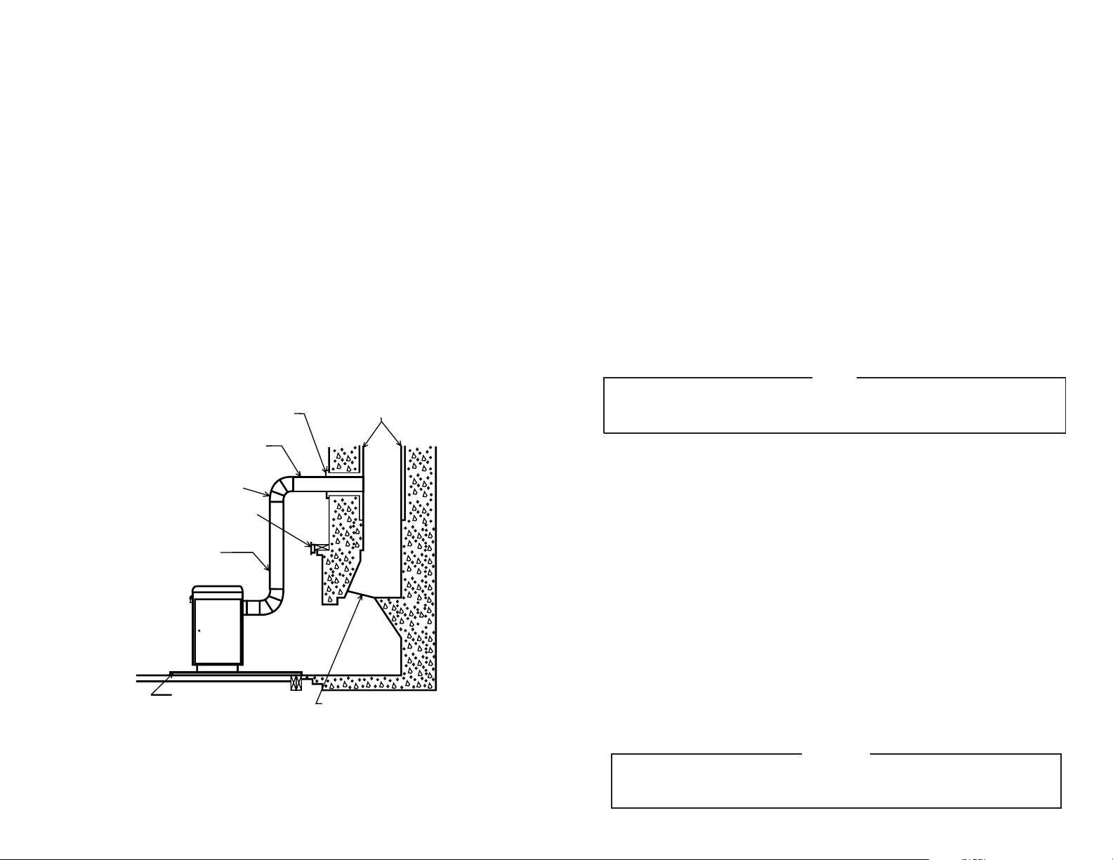
Always connect this heater to a chimney or
vent to the outside. Never vent to another
room or inside a building.
Do not connect a COAL burning heater to an
aluminum Type B gas vent. This is not safe
and is prohibited by all codes. This heater
requires connection to approved chimneys:
Either a factor built 6" UL 103HT or a lined and
approved and recently inspected and cleaned
masonry chimney with a 6" flue, preferably
round. A larger masonry flue may be used, so
long as the flue-section diameter is not greater
than 50 sq. in.
The chimney portion (whether factory-built or
masonry) must be tall enough to provide
sufficient draft and safe exit of smoke and
combustion products. Please refer to Page 5.
Be sure that your Chimney is safely con-
structed and in good repair. Have the chimney
inspected by the Fire Department or a quali-
fied inspector (such as a Chimney sweep).
Your insurance company may be able to
recommend a qualified inspector.
Inspect chimney connector and chimney twice
monthly during the heating season for any
deposit of creosote or soot which must be
removed.
Provide air for combustion from outside the
house into the room where the heater is
located. If the intake is not in the same room,
air must have free access to the room.
CAST IRON PARTS MUST BE "SEASONED"
TO AVOID CRACKING. BUILD ONLY SMALL
FIRES ON FIRST USE.
To prevent injury, do not allow anyone to use
this heater who is unfamiliar with the correct
operation of the heater. Do not allow children
to use or in any way operate this heater.
For further information on using your heater
safely, obtain a copy of the National Fire
Protection Association (NFPA) publication
"Using Coal and Wood Stoves Safely" NFPA
No. HS-10-1978. The address of the NFPA
is Battery March Park, Quincy, MA. 02269.
Keep the ash pit section free of excess
ashes. Do not allow ashes to stack higher
than the sides of the ash pan.
DISPOSAL OF ASHES- Ashes should be
placed in a metal container with a tight fitting
lid. Keep the closed container on a non-
combustible floor or on the ground, well away
from all combustible materials. Keep the
ashes in the closed container until all cinders
have thoroughly cooled. The ashes may be
buried in the ground or picked up by a refuse
collector.
CAUTION: The special paints used on your
heater may give off some smoke while they
are curing during first few fires. Build small
fires at first. The metals used in construction
of the heater has a light coating of oil. This
could give off smoke and/or odors when
heater is used for the first couple of times.
This should disappear after a short period of
time. Once this burn-off has occurred, it
should not reoccur.
CARING FOR PAINTED PARTS- This heater
has a painted outside jacket, which is durable
but it will not stand rough handling or abuse.
When installing your heater, use care in
handling. Clean with soap and warm water
when heater is not hot. DO NOT use any
harsh chemicals (acids or caustics) or scour-
ing powder, as these wear and dull the finish.
KEEP THE FEED DOOR, ASH DOOR AND
CABINET DOOR CLOSED AT ALL TIMES
EXCEPT WHILE TENDING THE HEATER.
DO NOT OVERFIRE THE HEATER. THIS
WILL HAPPEN IF THE FEED DOOR, OR
PARTICULARLY THE ASH DOOR, IS LEFT
OPEN DURING OPERATION. UNDER EX-
TREME CONDITIONS THIS CAN PRO-
DUCE DANGEROUS RESULTS. AS A MINI-
MUM, IT WILL ALLOW THE PAINT TO
DISCOLOR.
Use coal only. DO NOT USE the coal bricks
that are manufactured from coal dust and a
wax-type binder.
CAUTION: DO NOT TOUCH THE
HEATER UNTIL IT HAS COOLED.
ALWAYS WEAR GLOVES WHEN
REFUELING THIS UNIT OR WORKING
WITH METAL CABINET PARTS.
10.
11.
12.
13.
14.
15.
16.
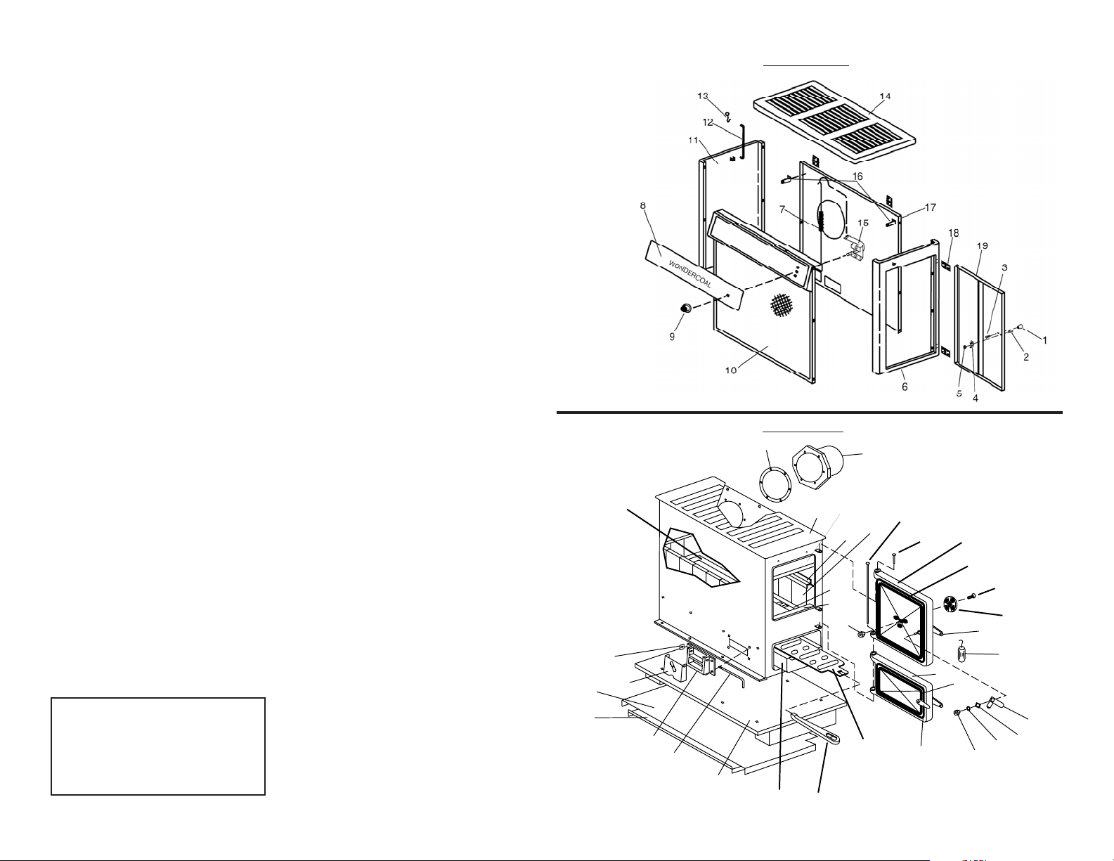
INTERIOR REPAIR PARTS LIST - (SEE PAGE 15)
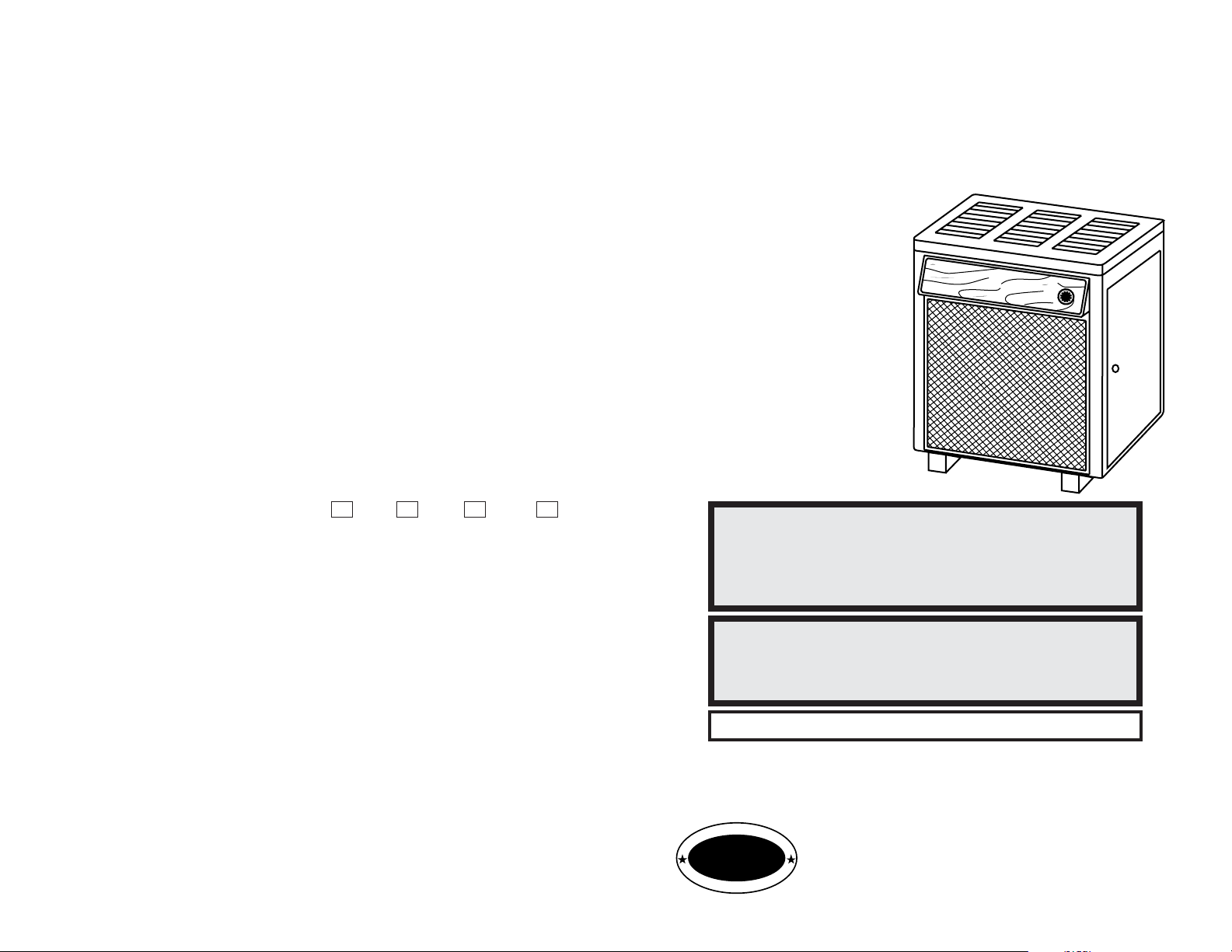
AUTOMATIC COAL BURNING CIRCULATOR
Key No. Description Qty. Part No.
1 Shaker 1 40045
2 Second Heat Shield Assembly 1 22030
3 Heat Shield 1 22110
4 Draft Damper Hinge Pin 1 17200
5 Draft Damper Frame 1 40075
* 1/4-20 x 3/4 MS 4 83086
* 1/4-20 Kep Nut 4 83250
6 Base 1 67859
7 Draft Control Damper 1 67132
8 Clip 1 83818
9 Coal Grate 1 40101
10 Grate Support 2 22536
* 1/4-20 x 3/4 MS 8 83086
* Nut 1/4-20 Kep 8 83250
11 Firebrick 10 89066
12 Firebox 1 67858
13 Front & Back Liner 3 40100
14 Flue Collar 1 40246
15 Flue Collar Gasket 1 88032
16 Firebrick Retainer 2 40132
* 1/4-20 x 1 6 83227
* 1/4-20 Kep Nut 6 83250
* Smoke Curtain Bracket 2 22171
* 1/4-20 Kep Nut 2 83250
* Machine Screw (1/4-20 x 3/4 PH) 2 83086
17 Hinge Pin 1 83872
18 Smoke Curtain 1 22090
19 Coal Grate Frame 1 40102
20 Feed Door Assembly 1 69519
21 1/4-20 Kep Nut 2 83250
22 Draft Wheel 1 40056
23 Machine Screw (1/4-20 x 1) 1 83227
24 Door Handle 2 40091
25 Wood Handle 1 89523
26 Feed Door Rope Gasket 45" 88033
27 Ash Door Assembly 1 69520
28 Two-Step Latch 1 22434
29 Washer, Flat 2 83045
30 1/4-20 Kep Nut 2 83250
31 Ash Door Gasket 29" 88033
32 Latch 1 22108
33 Ash Pan 1 67444
* 1/4-20 x 3/4 MS, SL, FL,2 6 83086
* 1/4-20 Kep Nut 6 83250
34 Latch Spacer 1 21467
35 Hinge Pin (Long) 1 83114
* NOT SHOWN