SCHWARZBECK MESS - ELEKTRONIK
An der Klinge 29 D-69250 Schönau Tel.: 06228/1001 Fax.: (49)6228/1003
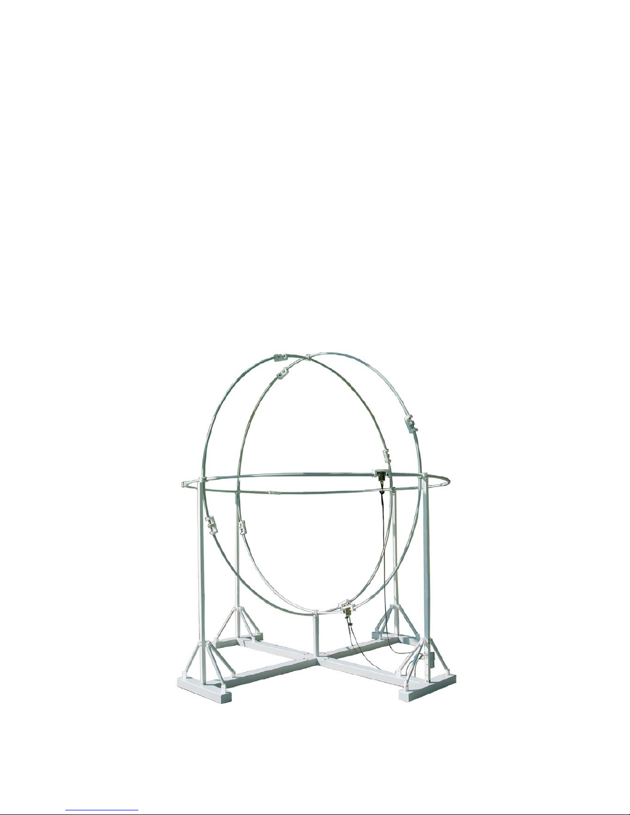
Montageanleitung 3-achsige Rahmenantenne HXYZ 9170 3 m
Assembly Instructions for 3-axis Large Loop Antenna HXYZ 9170 3 m
Schritt 2: Vormontage der Rahmen-Ringe
Die Rahmenantenne besteht aus drei gleichen
Ringen, die sich lediglich durch die
Bezeichnung der Achsen (x, y, und z)
unterscheiden. Jeder Ring besteht aus einem
Stromwandler, zwei Bedämpfungseinheiten mit
Widerständen und einer koaxialen
Durchverbindung, vier Hüllrohren, vier
Koakialkabeln RG 223/U und den notwendigen
Verbindungselementen aus Kunststoff. An den
Verbindungsstellen sind die Hüllrohre sowie die
zugehörigen Verbindungswinkel mit
Klebeschildern markiert (XA-XD, YA-YD, ZA-
ZD). Es wird empfohlen, die Montage der
Ringe auf dem Boden durchzuführen
(Platzbedarf 10 m x 4 m). Zur Schonung des
Materials ist eine Unterlage aus Karton oder
eine Plane hilfreich. Die Montage beginnt beim
Stromwandler mit Hüllrohr, dann wird eine
Bedämpfungseinheit mit Hüllrohr hinzugefügt,
als nächstes folgt die Durchverbindung mit
Hüllrohr und anschließend nochmals eine
Bedämpfungseinheit mit Hüllrohr. Auf dem
Boden liegend wird die 9.45 m lange Hüllrohr-
Kette zum Ring geschlossen, die
Verbindungswinkel ggfs. ausgerichtet und alle
Schrauben mit einem Inbusschlüssel SW 3
angezogen. Die vier Koaxialkabel werden in
die Hüllrohre eingeschoben und und mit den
BNC-Buchsen der betreffenden Teile
verbunden. Bei den anderen Ringen wird
analog verfahren.
Step 2: Pre-assembly of the loop rings
The loop antenna system consists of three
equal rings. The only difference between
the rings is the label designation with x, y
and z. Each ring is composed of a current
transformer, two resistive slits for damping
the loop self resonance, four double
shieded coaxial cables of type RG 223/U
with BNC-male-connectors, four cladding
tubes, the related fixture bars and a through
connection. The connection of the cladding
tubes to the fixture bars is labelled with XA-
XD, YA-YD and ZA-ZD. It is recommended
to mount the ring on the ground, the
required area is 10 m x 4 m. To prevent the
ring from being scratched during assembly
the ground can be covered by corrugated
paper. The assembly starts with the current
transformer with cladding tube, followed by
a slit with cladding tube, followed by a
through with cladding tube and again
followed by a slit with cladding tube. This
9.45 m long straight tube must be formed to
a closed ring laying on the ground by at
least two persons. As soon as the ring is
closed, the location of the clamping bars
can be corrected if neccessary and the
screws locked with an allen wrench size 3
mm. The four double shielded coaxial
cables can now be pushed into the cladding
tubes and connected to the respective
terminals. The other rings are mounted on
the same way.
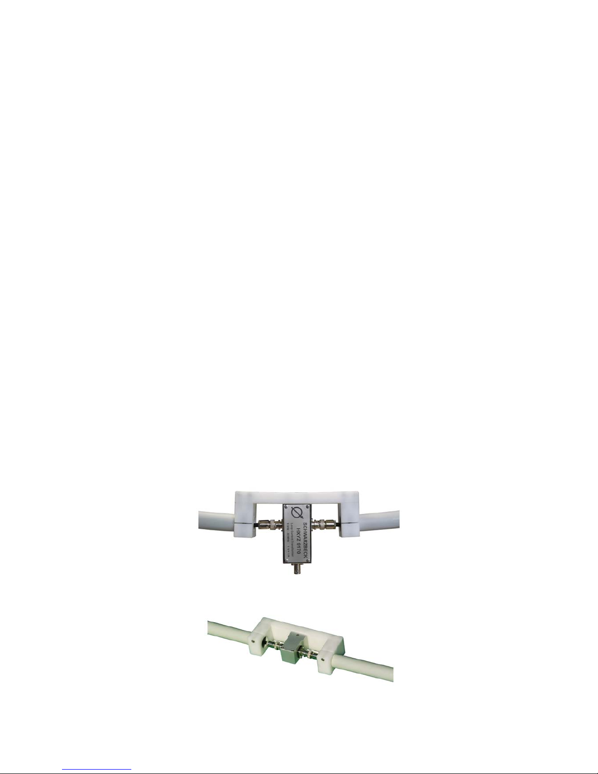
Bild 7: Stromwandler
Fig. 7: Current transformer
Bild 8: Bedämpfungseinheit
Fig. 8: Resistive Slit