Schwarzbeck XSLP 9142 User manual

SCHWARZBECK MESS - ELEKTRONIK
An der Klinge 29 D-69250 Schönau Tel.: (+49)6228/1001
XSLP 9142
Kreuzpolarisierte Breitband UHF-SHF Log.-Per. Messantenne
Dual Polarized UHF-SHF Broadband Log.-Per. Test-Antenna
800 MHz ... 3 (5) GHz
Handbuch
Manual

SCHWARZBECK MESS - ELEKTRONIK
An der Klinge 29 D-69250 Schönau Tel.: 06228/1001 Fax.: (49)6228/1003
XSLP 9142 UHF-SHF Breitband Log.-Per. Antenne
XSLP 9142 UHF-SHF Broadband Log.-Per. Antenna
22
180
200
474
Technische Daten: XSLP 9142 Specifications:
Bauart:
Linear zweifach (kreuz-) polarisierte
Logarithmisch Periodische
Breitbandantenne in Aluminium-
ausführung für Empfangs- und
Sendeanwendungen.
Type:
Linear dual polarized Logarithmic
Periodic Broadband Antenna
(Aluminium tubing) for Receive and
Transmit Applications.
Frequenzbereich, nominell: 800 MHz. ... 3 GHz Nominal Frequency Range:
Nutzbarer Frequenzbereich: 700 MHz ... 5 GHz Usable Frequency Range:
Isotropgewinn: typ.: 4 ... 7 dBi Isotropic Gain:
Antennenfaktor: 24 ... 34 ( 42) dB/m Antenna Factor:
Impedanz, nominell: 50 ΩNominal Impedance:
Stehwellenverhältnis SWR typisch: 1.5 - 3 Standing Wave Ratio SWR typical:
Vor- Rückverhältnis: > 15 dB Front to Back Ratio:
Polarisationsentkopplung: typ. 15 dB Cross Polarisation Rejection:
3 dB Öffnungswinkel typ.(E-Ebene): 50°-80° 3 dB Beamwidth typ. (E-Plane):
3 dB Öffnungswinkel typ.(H-Ebene): 90°-170° 3 dB Beamwidth typ. (H-Plane):
Max. Eingangsleistung: 100 W (intermitt.)
50 W (cont.) Max. Input Power:
Anschlußart: N-Buchsen N-Connectors female
Halterung: 22 mm Rohr, Rastring Mount: 22 mm Tube, Indexing Ring
Breite x Länge x Dicke: 200 x 474 (200) x 200 mm Width x Length x Thickness:
Gewicht: 0.8 kg Weight:

SCHWARZBECK MESS - ELEKTRONIK
An der Klinge 29 D-69250 Schönau Tel.: 06228/1001 Fax.: (49)6228/1003
XSLP 9142 UHF-SHF Breitband Log.-Per. Antenne
XSLP 9142 UHF-SHF Broadband Log.-Per. Antenna
Zuordnung der Polarisationsebenen Assignment of Polarisation Planes
Die XSLP 9142 verfügt über zwei
unabhängige Polarisationsebenen, die
senkrecht zueinander stehen. Die Zuordnung
der N-Buchsen zur entsprechenden
Polarisationsebene ist in der Abbildung
skizziert. Der Innenleiter der N-Buchse steht
immer senkrecht auf der Polarisationsebene.
Beispiel: Mit der Buchse "B" soll
Horizontalpolarisation eingestellt werden. Die
Antenne wird um die Längsachse gedreht, so
daß die mit "B" bezeichneten Elemente
waagrecht liegen. Die Buchse "B" zeigt dann
entweder nach oben oder unten.
The XSLP 9142 has two orthogonal
polarisation planes, which can be accessed
independantly via N-connectors. The
assignment of the N-connector to the
corresponding polarisation plane is shown in
the above picture. The Inner conductor of the
N-connector stands always perpendicular on
the corresponding polarisation plane. Example:
Connector "B" should be used for horizontal
polarisation. The antenna is rotated around its
longitudinal axis until the elements assigned
with "B" are horizontal. The connector "B"
faces either upwards or towards ground.
Entkopplung der Polarisationsebenen Decoupling of the Polarisation Planes
Obwohl beide Polarisationsebenen exakt
senkrecht aufeinander stehen, sind die
Ebenen nicht 100% entkoppelt. Ein
horizontal polarisiertes Feld wird auch vom
vertikalen Zweig der Antenne erfaßt, wenn
auch mit weitaus geringerer Anzeige.
Typische Entkopplungswerte liegen zwischen
15 und 20 dB. Die Entkopplung der Ebenen
hängt ausserdem sehr stark von
Umgebungsreflexionen ab. Optimale
Entkopplungswerte erreicht man unter
Freiraumbedingungen. Bei höheren
Frequenzen nimmt die
Polarisationsentkopplung stetig ab, der Grund
hierfür ist der Elementversatz an der Spitze,
der im Vergleich zur Elementlänge zunimmt.
Although the two polarisation planes are
exactly orthogonal to each other, there is no
100% decoupling between them. A horizontal
polarised field contributes also to the indication
of the vertical polarised antenna section, but
with reduced effect. Typical decoupling values
for the cross polarised fieldstrength indication
are 15 to 20 dB. The decoupling of the
polarisation planes depends a lot on
environmental reflections. Best decoupling
results can be achieved under free-space
conditions. The cross polarisation decoupling
decreases at higher frequencies due to the
element displacement at the antenna tip, which
approaches to the element length itself.

SCHWARZBECK MESS - ELEKTRONIK
An der Klinge 29 D-69250 Schönau Tel.: 06228/1001 Fax.: (49)6228/1003
XSLP 9142 UHF-SHF Breitband Log.-Per. Antenne
XSLP 9142 UHF-SHF Broadband Log.-Per. Antenna
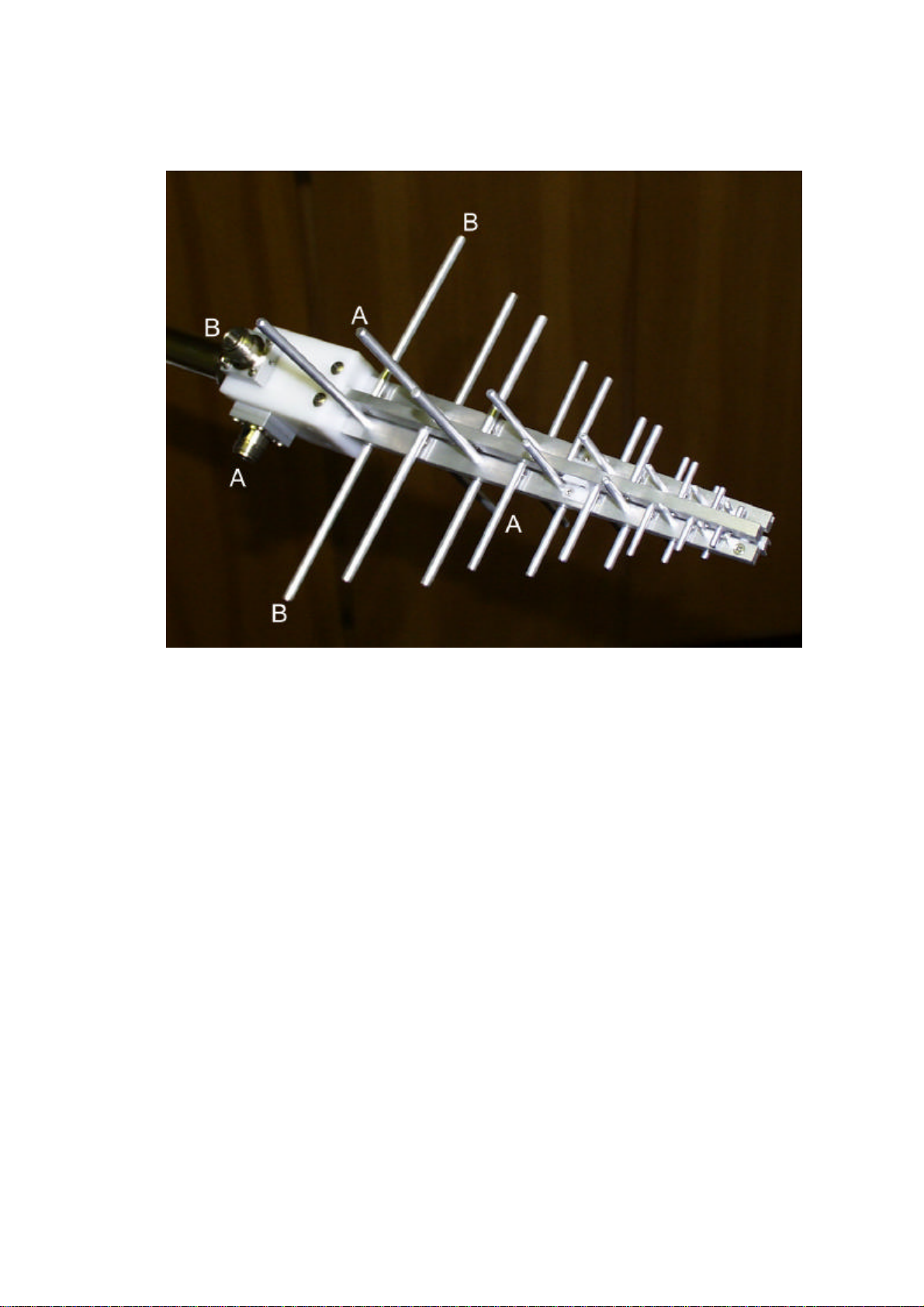
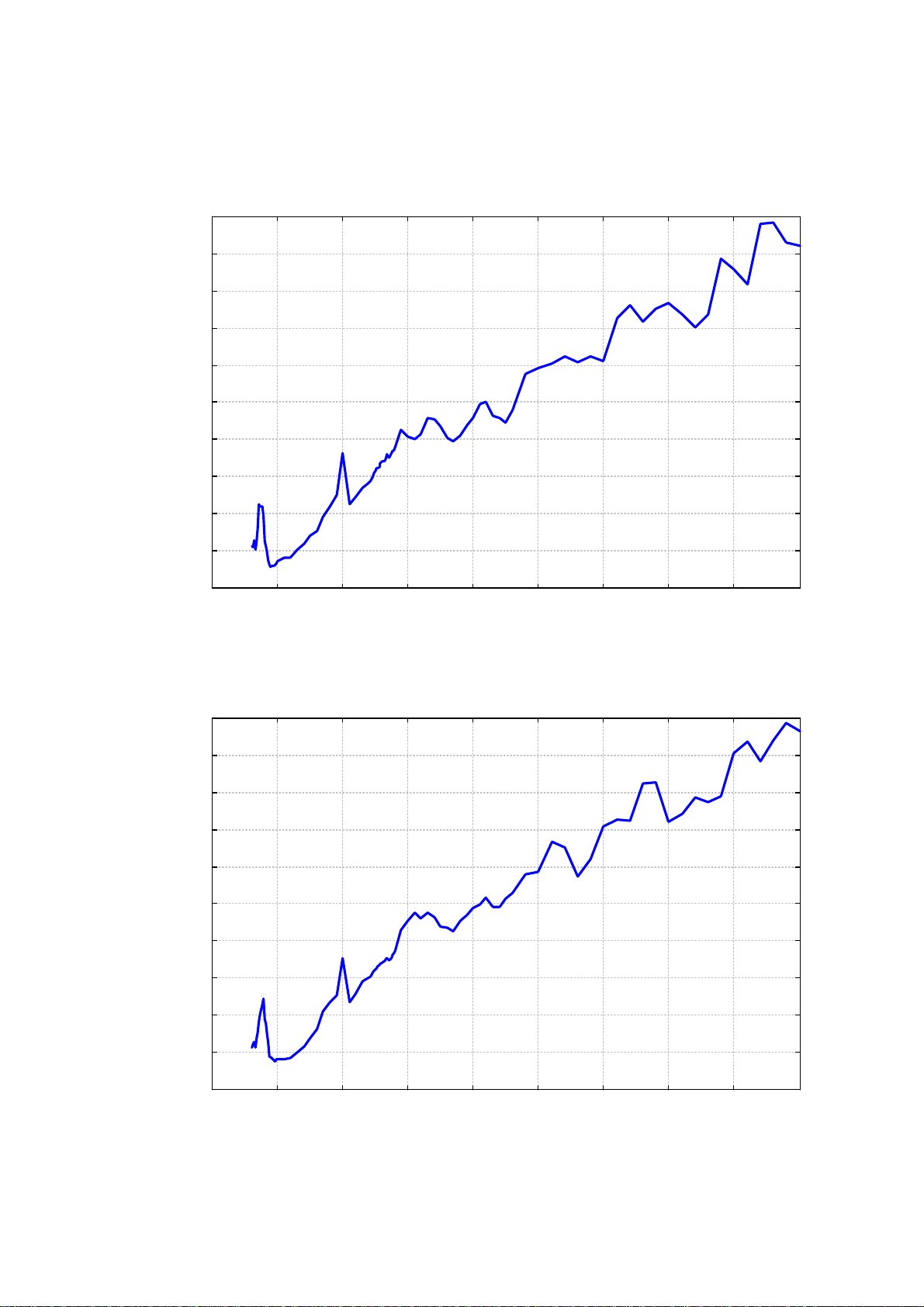
Gleichheit der Polarisationsebenen Equality of Polarisation Planes
Aus konstruktiven Gründen sind leichte
Unterschiede zwischen den beiden
Polarisationsebenen erkennbar. Die Ursache
ist die unterschiedliche Entfernung des
Speisepunktes zu den aktiven Elementen. Im
Regelfall liegen die Abweichungen der
Ebenen untereinander bei weniger als 1 dB,
maximal jedoch bei ca. 1.5 dB. Insbesondere
bei höheren Frequenzen sollten daher bei
höchstem Genauigkeitsanspruch die
zugehörigen Daten zur Polarisationsebene
verwendet werden.
Small differences between the polarisation
planes are recognizable for construction
reasons. The feeding point distance to the
active element is somewhat different. Normally
the deviations between the planes are less
than 1 dB, as worst case 1.5 dB difference can
be assumed. Especially at higher frequencies
and for best accuracy it is recommended to
use the data which is explicitly assigned to the
respective polarisation plane (Sections A or B).
Allgemeine Hinweise General Hints
Für höchste Genauigkeitsansprüche kann es
nützlich sein, ein geeignetes
Festdämpfungsglied mit 3 dB bis 10 dB zu
verwenden. Man erreicht dadurch eine
Anpassungsverbesserung, die allerdings den
Gewinn um den Betrag der Dämpfung
herabsetzt und den Antennenfaktor um
denselben Betrag erhöht. Bei einem SWR
von < 2 kann in der Regel auf ein
Dämpfungsglied verzichtet werden.
Bei Antennenmessungen im
Mikrowellenbereich werden auch
nichtleitende Materialien wie z.B. Kunststoffe
zu Reflektoren. Insbesondere im
unmittelbaren Nahbereich der Antenne
sollten daher keine großen Masthalterungen
und ähnliches eingesetzt werden.
For highest accuracy requirements a suitable
fixed attenuator (3 dB to 10 dB) may be useful
under certain circumstances. Inserting a fixed
attenuator at the antenna terminal improves
impedance matching, but also reduces the gain
and increases the antenna factor by the
attenuation value. With an SWR < 2 the
attenuator may be omitted in most applications.
Antenna measurements in the microwave
frequency range suffer from environmental
reflections, which may even occur at
nonmetallic surfaces as e.g. plastic. Therefore
it is recommended to avoid large mast
adapters and other big parts in the near
surrounding of the antenna.
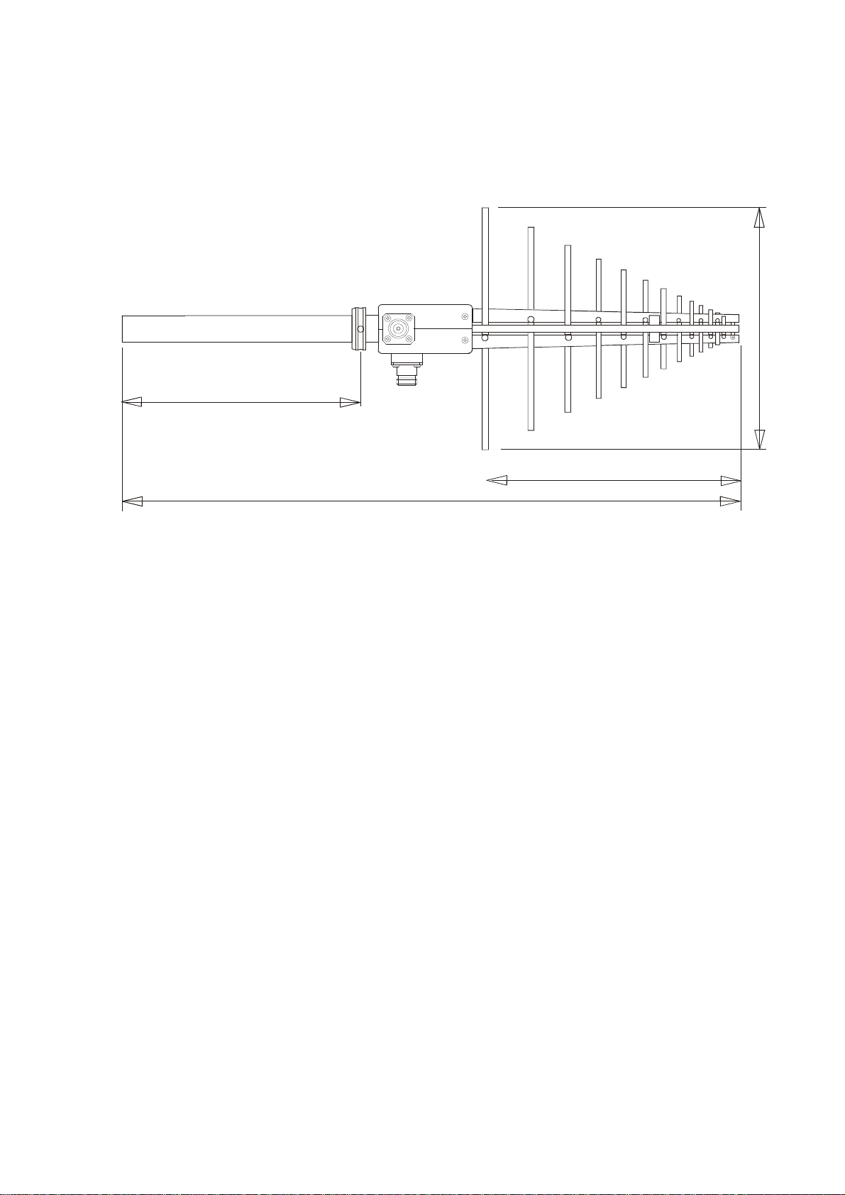
Antennenbezugspunkt Antenna reference point
Als Antennenbezugspunkt wurde bei der
Kalibrierung die Mitte zwischen Spitze und
hinterem Element gewählt. Dies führt bei der
kurzen Antennenlänge zu hinreichend
genauen Ergebnissen. Für Messungen in
sehr geringem Abstand (< 0.7 m) von der
Antenne ist es sinnvoll, die tatsächliche Lage
des Phasenzentrums als Messentfernung
anzunehmen. Das Phasenzentrum liegt etwa
im Bereich, in dem die Elementlänge der
halben Wellenlänge entspricht. Beispiel: Bei
1 GHz beträgt die Wellenlänge 30 cm, das
Phasenzentrum liegt daher beim Element mit
der Länge 15 cm (ca. 15.5 cm hinter der
Spitze)
The center between antenna tip and longest
element was used as antenna reference point
during calibration. This leads to accurate
results on most frequently used measuring
distances. For measurements on short
distances (< 0.7 m) the accuracy may be
improved, if the actual position of the phase
center is considered. The phase center
position is located near the element in half-
wave resonance. Example: The wavelength at
1 GHz is 30 cm, the corresponding element
would be 15 cm long (the location of the phase
center is the approx. 15.5 cm behind the
antenna tip)

SCHWARZBECK MESS - ELEKTRONIK
An der Klinge 29 D-69250 Schönau Tel.: 06228/1001 Fax.: (49)6228/1003
XSLP 9142 UHF-SHF Breitband Log.-Per. Antenne
XSLP 9142 UHF-SHF Broadband Log.-Per. Antenna
Section A Section B
Frequency Gain(Isotr.) Ant.-Factor Gain(Isotr.) Ant.-Factor
Frequenz Isotrop-
gewinn Ant.-Wand-
lungsmaß Isotrop-
gewinn Ant.-Wand-
lungsmaß
MHz dBi dB/m dBi dB/m
800.00 4.05 24.23 4.04 24.24
810.00 4.22 24.17 3.98 24.41
820.00 3.95 24.55 3.95 24.55
830.00 4.50 24.10 4.35 24.25
840.00 4.20 24.51 3.96 24.75
850.00 3.60 25.21 3.75 25.06
860.00 2.42 26.49 3.25 25.66
870.00 2.63 26.38 2.94 26.07
880.00 2.75 26.36 2.52 26.59
890.00 3.32 25.89 2.33 26.88
900.00 4.80 24.50 3.51 25.79
910.00 5.17 24.23 3.80 25.60
920.00 5.52 23.98 4.49 25.01
930.00 6.07 23.52 5.02 24.57
940.00 6.45 23.23 5.91 23.77
950.00 6.62 23.15 6.04 23.73
960.00 6.71 23.16 6.16 23.71
970.00 6.75 23.21 6.41 23.55
980.00 6.80 23.24 6.52 23.52
990.00 6.78 23.35 6.50 23.63
1000.00 6.81 23.41 6.61 23.61
1050.00 7.03 23.61 6.99 23.65
1100.00 7.40 23.65 7.35 23.70
1150.00 7.34 24.09 7.44 23.99
1200.00 7.42 24.38 7.51 24.29
1250.00 7.36 24.80 7.39 24.77
1300.00 7.43 25.07 7.23 25.27
1350.00 7.01 25.82 6.65 26.18
1400.00 6.74 26.40 6.45 26.69
1450.00 6.40 27.05 6.38 27.07
1500.00 4.47 29.27 4.63 29.11
1550.00 7.49 26.54 7.33 26.70
1600.00 7.42 26.88 7.15 27.15
1650.00 7.15 27.42 6.72 27.85
1700.00 7.20 27.63 6.82 28.01
1710.00 7.10 27.78 6.78 28.10
1720.00 7.01 27.92 6.75 28.18
1730.00 6.93 28.05 6.67 28.31
1740.00 6.85 28.18 6.64 28.39
1750.00 6.83 28.25 6.61 28.47
1760.00 6.70 28.43 6.58 28.55
1770.00 6.75 28.43 6.56 28.62
1780.00 6.68 28.55 6.55 28.68
1790.00 6.56 28.72 6.53 28.75
Frequency Gain(Isotr.) Ant.-Factor Gain(Isotr.) Ant.-Factor
MHz dBi dB/m dBi dB/m
Section A Section B

SCHWARZBECK MESS - ELEKTRONIK
An der Klinge 29 D-69250 Schönau Tel.: 06228/1001 Fax.: (49)6228/1003
XSLP 9142 UHF-SHF Breitband Log.-Per. Antenne
XSLP 9142 UHF-SHF Broadband Log.-Per. Antenna
Section A Section B
Frequenz Isotrop-
gewinn Ant.-Wand-
lungsmaß Isotrop-
gewinn Ant.-Wand-
lungsmaß
MHz dBi dB/m dBi dB/m
1800.00 6.47 28.86 6.51 28.82
1810.00 6.57 28.80 6.50 28.87
1820.00 6.60 28.82 6.49 28.93
1830.00 6.48 28.99 6.45 29.02
1840.00 6.31 29.21 6.43 29.09
1850.00 6.47 29.09 6.56 29.00
1860.00 6.57 29.04 6.65 28.96
1870.00 6.37 29.29 6.57 29.09
1880.00 6.30 29.40 6.45 29.25
1890.00 6.35 29.40 6.39 29.36
1900.00 6.23 29.57 6.32 29.48
1950.00 5.50 30.52 5.41 30.61
2000.00 6.07 30.17 5.17 31.07
2050.00 6.41 30.05 4.93 31.53
2100.00 6.37 30.29 5.44 31.22
2150.00 5.70 31.17 5.37 31.50
2200.00 6.00 31.07 5.77 31.30
2250.00 6.53 30.73 6.49 30.77
2300.00 7.34 30.11 6.72 30.73
2350.00 7.76 29.88 7.09 30.55
2400.00 7.58 30.24 6.74 31.08
2450.00 7.21 30.79 6.57 31.43
2500.00 7.04 31.14 6.37 31.81
2550.00 6.43 31.92 6.40 31.95
2600.00 6.46 32.06 6.15 32.37
2650.00 7.40 31.28 6.85 31.83
2700.00 7.72 31.13 6.98 31.87
2750.00 8.08 30.93 6.73 32.28
2800.00 7.58 31.58 6.56 32.60
2900.00 5.95 33.52 5.85 33.62
3000.00 5.90 33.86 6.02 33.74
3100.00 5.95 34.10 4.68 35.37
3200.00 5.85 34.47 5.26 35.06
3300.00 6.42 34.17 7.09 33.50
3400.00 6.39 34.46 6.45 34.40
3500.00 6.87 34.23 4.91 36.19
3600.00 4.82 36.53 4.82 36.53
3700.00 4.31 37.27 5.08 36.50
3800.00 5.47 36.35 3.32 38.50
3900.00 5.00 37.04 3.49 38.55
4000.00 4.89 37.37 5.84 36.42
4100.00 5.77 36.71 5.61 36.87
4200.00 6.61 36.07 4.96 37.72
4300.00 6.18 36.71 5.41 37.48
4400.00 3.37 39.72 5.32 37.77
4500.00 4.07 39.21 3.14 40.14
4600.00 5.14 38.34 2.75 40.73
4700.00 2.06 41.60 4.01 39.65
4800.00 2.12 41.72 3.02 40.82
4900.00 3.42 40.60 2.28 41.74
5000.00 3.76 40.44 2.88 41.32
Frequency AGain(Isotr.) Ant.-Factor Gain(Isotr.) Ant.-Factor
MHz dBi dB/m dBi dB/m
Section A Section B

SCHWARZBECK MESS - ELEKTRONIK
An der Klinge 29 D-69250 Schönau Tel.: 06228/1001 Fax.: (49)6228/1003
XSLP 9142 Kalibrierdaten (Teilbereich 0.8 - 1 GHz)
XSLP 9142 Calibration Data (Subrange 0.8 - 1 GHz)
2
2.5
3
3.5
4
4.5
5
5.5
6
6.5
7
800 850 900 950 1000
Isotropic gain [dBi]
Frequency [MHz]
Section A
2
2.5
3
3.5
4
4.5
5
5.5
6
6.5
7
800 850 900 950 1000
Isotropic gain [dBi]
Frequency [MHz]
Section B

SCHWARZBECK MESS - ELEKTRONIK
An der Klinge 29 D-69250 Schönau Tel.: 06228/1001 Fax.: (49)6228/1003
XSLP 9142 Kalibrierdaten (Teilbereich 1.7 - 1.9 GHz)
XSLP 9142 Calibration Data (Subrange 1.7 - 1.9 GHz)
6
6.2
6.4
6.6
6.8
7
7.2
7.4
7.6
7.8
8
1700 1750 1800 1850 1900
Isotropic gain [dBi]
Frequency [MHz]
Section A
6
6.2
6.4
6.6
6.8
7
7.2
7.4
7.6
7.8
8
1700 1750 1800 1850 1900
Isotropic gain [dBi]
Frequency [MHz]
Section B

SCHWARZBECK MESS - ELEKTRONIK
An der Klinge 29 D-69250 Schönau Tel.: 06228/1001 Fax.: (49)6228/1003
XSLP 9142 UHF-SHF Breitband Log.-Per. Antenne
XSLP 9142 UHF-SHF Broadband Log.-Per. Antenna
2
3
4
5
6
7
8
9
500 1000 1500 2000 2500 3000 3500 4000 4500 5000
Isotropic gain [dBi]
Frequency [MHz]
Section A
2
3
4
5
6
7
8
9
500 1000 1500 2000 2500 3000 3500 4000 4500 5000
Isotropic gain [dBi]
Frequency [MHz]
Section B

SCHWARZBECK MESS - ELEKTRONIK
An der Klinge 29 D-69250 Schönau Tel.: 06228/1001 Fax.: (49)6228/1003
XSLP 9142 UHF-SHF Breitband Log.-Per. Antenne
XSLP 9142 UHF-SHF Broadband Log.-Per. Antenna
22
24
26
28
30
32
34
36
38
40
42
500 1000 1500 2000 2500 3000 3500 4000 4500 5000
Antenna Factor [dB/m]
Frequency [MHz]
Section A
22
24
26
28
30
32
34
36
38
40
42
500 1000 1500 2000 2500 3000 3500 4000 4500 5000
Antenna Factor [dB/m]
Frequency [MHz]
Section B

SCHWARZBECK MESS - ELEKTRONIK
An der Klinge 29 D-69250 Schönau Tel.: 06228/1001 Fax.: (49)6228/1003
XSLP 9142 Kalibrierdaten (Teilbereich 0.8 - 1 GHz)
XSLP 9142 Calibration Data (Subrange 0.8 - 1 GHz)
23
23.5
24
24.5
25
25.5
26
26.5
27
800 850 900 950 1000
Antenna Factor [dB/m]
Frequency [MHz]
Section A
23
23.5
24
24.5
25
25.5
26
26.5
27
800 850 900 950 1000
Antenna Factor [dB/m]
Frequency [MHz]
Section B

SCHWARZBECK MESS - ELEKTRONIK
An der Klinge 29 D-69250 Schönau Tel.: 06228/1001 Fax.: (49)6228/1003
XSLP 9142 Kalibrierdaten (Teilbereich 1.7 - 1.9 GHz)
XSLP 9142 Calibration Data (Subrange 1.7 - 1.9 GHz)
27
27.5
28
28.5
29
29.5
30
1700 1750 1800 1850 1900
Antenna Factor [dB/m]
Frequency [MHz]
Section A
27
27.5
28
28.5
29
29.5
30
1700 1750 1800 1850 1900
Antenna Factor [dB/m]
Frequency [MHz]
Section B

SCHWARZBECK MESS - ELEKTRONIK
An der Klinge 29 D-69250 Schönau Tel.: 06228/1001 Fax.: (49)6228/1003
XSLP 9142 UHF-SHF Breitband Log.-Per. Antenne
XSLP 9142 UHF-SHF Broadband Log.-Per. Antenna
VSWR an der N-Buchse "A"
1
2
3
4
5
6
7
8
9
10
1000 1500 2000 2500 3000
VSWR
Frequency [MHz]
XSLP 9142
'xslp101a.swr'
VSWR an der N-Buchse "B"
1
2
3
4
5
6
7
8
9
10
1000 1500 2000 2500 3000
VSWR
Frequency [MHz]
XSLP 9142
'xslp101b.swr'

SCHWARZBECK MESS - ELEKTRONIK
An der Klinge 29 D-69250 Schönau Tel.: 06228/1001 Fax.: (49)6228/1003
XSLP 9142 UHF-SHF Breitband Log.-Per. Antenne
XSLP 9142 UHF-SHF Broadband Log.-Per. Antenna
Kreuzpolarisationsentkopplung im linear polarisierten Wellenfeld
-40
-35
-30
-25
-20
-15
-10
-5
0
500 1000 1500 2000 2500 3000 3500 4000 4500 5000
Cross Polarisation Decoupling [dB]
Frequency [MHz]
XSLP 9142
'xpol58.dat'
Entkopplung der N-Buchsen
-50
-40
-30
-20
-10
0
500 1000 1500 2000 2500 3000 3500 4000 4500 5000
Internal Decoupling at N-Connectors [dB]
Frequency [MHz]
XSLP 9142
'decnab.dat'

SCHWARZBECK MESS - ELEKTRONIK
An der Klinge 29 D-69250 Schönau Tel.: 06228/1001 Fax.: (49)6228/1003
XSLP 9142 Skizze der Bezugspunkte
XSLP 9142 Sketch of Reference Points
Mitte-Prüfling
Diese Anordnung wird
vorwiegend für
Emissionsmessungen
verwendet.
Center-EuT
This setup is most
popular for Emission
testing.
Spitze-Prüfling
Diese Anordnung wird
vorwiegend für
Immunitätsprüfungen
verwendet.
Tip-EuT
This setup is most
popular for Immunity
testing.

SCHWARZBECK MESS - ELEKTRONIK
An der Klinge 29 D-69250 Schönau Tel.: 06228/1001 Fax.: (49)6228/1003
XSLP 9142 Erzeugung definierter Feldstärken
XSLP 9142 Generating defined Fieldstrength
Erzeugung von Feldstärken unter Freiraum-
bedingungen vor der Spitze der Log.-Per. Antenne
(siehe Skizze und Angaben bei den Kurvenscharen).
Wenn Anteile von Umgebungsreflexionen vorhanden
sind, kann dies zu einer frequenz- und
höhenabhängigen Änderung der Feldstärke führen.
Die Leistungsangaben beziehen sich auf eine 50 Ω
Quellimpedanz und unmodulierte Hochfrequenz (CW).
Bei 80% Amplitudenmodulation ist die 1.8-fache
Spannungsaussteuerung erforderlich, was in einem
ca. 3.24-fachen Leistungsbedarf resultiert. Zur
Steigerung der Feldstärke um den Faktor 10 ist die
100-fache Verstärkerleistung erforderlich.
Field strength generated under free-space
conditions at a separation from the antenna
tip (see diagrams for several combinations of
power and distance). If environmental
reflections are present, this may lead to
frequency and height dependent
fieldstrengths. The power figures refer to a 50
Ωsource and an unmodulated (cw) signal. An
80% Amplitude Modulation requires a 1.8
times higher voltage, resulting in 3.24 times
higher power compared to cw. A fieldstrength
increase of factor 10 requires 100 times
amplifier-power.
Bei der Erzeugung von hohen Feldstärken
müssen die relevanten Sicherheits-
vorschriften und Normen beachtet werden!
Missachtung dieser Vorschriften kann zu
Schädigungen der Gesundheit führen!
The safety precautions and relevant
standards must be considered while
performing tests with high
fieldstrength! Ignoring these
standards and precautions may result
in severe danger for health!

SCHWARZBECK MESS - ELEKTRONIK
An der Klinge 29 D-69250 Schönau Tel.: 06228/1001 Fax.: (49)6228/1003
USLP 9142 Erzeugte Feldstärke
USLP 9142 Generated Fieldstrength
Erzeugte Elektrische Feldstärke vor der Antennenspitze
unmoduliert, Eingangsleistung an N-Buchse, Reflexionsfreie Umgebung
Generated Electrical Fieldstrength in front of Antenna Tip
no modulation, Input Power at N-Connector, Anechoic Environmental Conditions
USLP 9142 Erzeugte Feldstärke in 1 m Abstand Spitze - Prüfling
1
10
100
1000 10000
E - Fieldstrength [V/m]
Frequency [MHz]
USLP 9142 Generated Fieldstrength 1 m Tip - EuT
1 W
2 W
5 W
10 W
20 W
50 W
100 W
USLP 9142 Erzeugte Feldstärke in 2 m Abstand Spitze - Prüfling
1
10
100
1000 10000
E - Fieldstrength [V/m]
Frequency [MHz]
USLP 9142 Generated Fieldstrength 2 m Tip - EuT
1 W
2 W
5 W
10 W
20 W
50 W
100 W
Die Diagramme "Erzeugte Feldtstärke" der USLP 9142 sind bis 3 GHz auch für die XSLP 9142
verwendbar.
The diagrams "Generated Fieldstrength" of USLP 9142 are also applicable for XSLP 9142 up to 3
GHz.

SCHWARZBECK MESS - ELEKTRONIK
An der Klinge 29 D-69250 Schönau Tel.: 06228/1001 Fax.: (49)6228/1003
USLP 9142 Erzeugte Feldstärke
USLP 9142 Generated Fieldstrength
Erzeugte Elektrische Feldstärke vor der Antennenspitze
unmoduliert, Eingangsleistung an N-Buchse, Reflexionsfreie Umgebung
Generated Electrical Fieldstrength in front of Antenna Tip
no modulation, Input Power at N-Connector, Anechoic Environmental Conditions
USLP 9142 Erzeugte Feldstärke in 3 m Abstand Spitze - Prüfling
1
10
100
1000 10000
E - Fieldstrength [V/m]
Frequency [MHz]
USLP 9142 Generated Fieldstrength 3 m Tip - EuT
1 W
2 W
5 W
10 W
20 W
50 W
100 W
USLP 9142 Erzeugte Feldstärke in 4 m Abstand Spitze - Prüfling
1
10
1000 10000
E - Fieldstrength [V/m]
Frequency [MHz]
USLP 9142 Generated Fieldstrength 4 m Tip - EuT
1 W
2 W
5 W
10 W
20 W
50 W
100 W
Die Diagramme "Erzeugte Feldtstärke" der USLP 9142 sind bis 3 GHz auch für die XSLP 9142
verwendbar.
The diagrams "Generated Fieldstrength" of USLP 9142 are also applicable for XSLP 9142 up to 3
GHz.
Table of contents
Other Schwarzbeck Antenna manuals
Popular Antenna manuals by other brands

Maxview
Maxview MXL028/65 Connect Installation, Satellite Information & Fault Finding

Intellian
Intellian v130G Installation and operation user guide

Cabletron Systems
Cabletron Systems RoamAbout 802.11 supplementary guide

ADC
ADC Digivance Installation and operation manual

GE
GE 43452 quick start guide

SMA
SMA EXTANT-US-40 installation manual