manuals.online logo
Brands
  1. Home
  2. •
  3. Brands
  4. •
  5. Schwarzbeck
  6. •
  7. Antenna
  8. •
  9. Schwarzbeck VAMP 9243 User manual

Schwarzbeck VAMP 9243 User manual

Handbuch Manual VAMP 9243 Seite Page 1
SCHWARZBECK MESS - ELEKTRONIK
An der Klinge 29 D-69250 Schönau Tel.: (+49)6228/1001
Fax.: (+49)6228/1003 E-mail: schwarz[email protected]
Rauscharme aktive vertikale Monopol-Antenne
VAMP 9243 9 kHz - 30 MHz
Low noise active vertical monopole antenna
1. Überblick VAMP 9243
Die aktive Monopol-Antenne VAMP 9243 besteht aus
einem vertikalen Stab und einem Anpaßverstärker.
Der Stab ist üblicherweise 1 Meter lang (andere Län-
gen möglich) und ist im Frequenzbereich 9 kHz-
30 MHz kurz gegenüber den betrachteten Wellenlän-
gen. Der Fußpunkt des Stabes wird durch den An-
paßverstärker hochohmig und kapazitätsarm belastet,
so daß das Wandlungsmaß über den gesamten Fre-
quenzbereich konstant ist. Die Schaltung zeigt bei
einem Wandlungsmaß (Antennenfaktor) von +10 dB
optimale Ergebnisse bei Rauschen und Großsignal-
verhalten und empfindliche Meßempfänger können
den Dynamikbereich der Antenne voll ausnutzen.
1. Overview VAMP 9243
The active monopole antenna VAMP 9243 consists of
a vertical rod and an impedance matching amplifier.
The rod has a standard length of 1m (other rod length
on request) and can be considered as short com-
pared to the wave length in the frequency range
9kHz-30 MHz.
The conversion factor is independent of the frequency
because of the extremely high impedance of the
matching amplifier.
The circuit gives best results of noise and intermodu-
lation for a conversion factor (antenna factor) of
+10 dB and sensitive measuring receivers are able to
use the whole dynamic range of the antenna.
Sollen sehr hohe Feldstärken gemessen werden, ver-
mindert ein optionaler Vorsteckteiler direkt am Stab die
Verstärkung um 20 dB. Um jegliche Beeinflussung
durch Stromnetz, Netzteil, Spannungsregler usw.
grundsätzlich zu vermeiden, verfügt die VAMP 9243
über eingebaute NiMH-Akkus. Typisch werden damit
Betriebszeiten von mindestens 50 Stunden erreicht.
Die Ladezeit mit dem Schnellladegerät beträgt
2-4 Stunden.
Stab und Verstärkergehäuse sind in Aluminiumbauwei-
se ausgeführt. Die Deckelplatte kann mit dem Anten-
nen-Gegengewicht (Bezugsmasse, Counterpoise) am
Aufbauort verschraubt werden. Die Buchsen und son-
stigen Bedienungsorgane liegen unterhalb der Deckel-
platte. Die Stablänge beginnt unmittelbar an der Dek-
kelplatte.
For very high fieldstrength, an optional plug-in attenua-
tor reduces the amplification by 20 db.
In order to avoid absolutely any influence by the mains,
power supply, voltage regulator a. o., the VAMP 9243
has built-in NiMH rechargeable batteries. The typical
operation time is at least 50 hours.
Charging time is 2-4 hours using the quick charger.
Rod antenna and amplifier cabinet are made of alumin-
ium.
The top plate can be fixed to the metal ground plane
(Counterpoise) with 4 screws.
The connectors and controls are situated below the to
plate. The rod length begins exactly at the top plate.
Handbuch Manual VAMP 9243 Seite Page 2
2. Technische Daten
2.1 Frequenzbereich:
9 kHz - 30 MHz
2.2 Wandlungsmaß ("Antennenfaktor"):
+10 dB/m +-1,5 dB
2.3 Obergrenze der Aussteuerung:
1 V/m (F=1 MHz, 1 dB
Kompression)
Eingangsteiler für höhere Feld-
stärken optional
2.4 Untergrenze
Bedingt durch Rauschen.
Typ. -3 dBµV/m bei 10 MHz
CISPR-Quasipeak
9 kHz Bandbreite
Typ. -8 dBµV/m bei 10 MHz
Mittelwert / Average
9 kHz Bandbreite
Weitere Angaben siehe Dia-
gramme weiter hinten in
diesem Handbuch.
2.5 Ausgang des Stabverstärkers:
BNC-Buchse, 50 Ω nom.
2.6 Stromversorgung:
9,6 V /1100 mAh NiMH
2.7 Abmessungen und Gewicht:
Stab: Länge einschließlich Schraub-
verbindung 1 m,
Gewicht ca. 0,2 kg.
Verstärker: 180x80x40 mm (LxBxH) ohne
BNC-Buchse und
Bedienungsorgane.
Deckelplatte 220x120 mm
Gewicht ca. 0,7 kg
2.8 Aufbau Stabantenne:
Aluminiumstab
Durchmesser 16 mm
mit M8 Innengewinde
2.9 Aufbau Verstärker:
Gehäuse aus Aluminium-
Profilen. Deckelplatte aus
Aluminium 3 mm stark
2.10 Stativgewinde: 1/4", 3/8"
2. Technical Data
2.1 Frequency range:
9 kHz - 30 MHz
2.2 Conversion factor ("Antenna factor")
+10 dB/m+-1.5 dB
2.3 Upper limit of field strength measurement:
1 V/m (F=1 MHz, 1 dB
compression)
Input attenuator for higher
field strength optional
2.4 Lower limit of field strength measurement:
Limitation by internal noise.
Typ. - 3 dBµV/m / 10 MHz
CISPR-Quasipeak
9 kHz bandwidth
Typ. -8 dBµV/m / 10 MHz
Average detector
9 kHz bandwidth
More information is given in
the diagrams further down
this manual.
2.5 Output of the monopole amplifier:
BNC-connector, fem., 50 Ωnom.
2.6 Power supply:
9,6 V /1100 mAh NiMH
2.7 Dimensions and weight:
Monopole (Rod): Length including thread
connection 1m
Weight approx. 0,2 kg
Amplifier: 180x80x40 mm (WxHxD)
without BNC-connector
(female) and controls.
Top plate 220x120 mm
Weight approx. 0,7 kg
2.8 Construction of the monopole (Rod):
Aluminium rod
16 mm diameter with
thread-hole M8
2.9 Construction of the amplifier:
Cabinet made of aluminium
profiles. Top plate
3mm aluminium material.
2.10 Threads for tripods: 1/4", 3/8"
Handbuch Manual VAMP 9243 Seite Page 3
3. Einschalten 3. Switching On
Die Antenne am Schalter EINschalten .
Die grüne LED muß nun leuchten.
Für die beiden LEDs gilt:
Grün: Akku OK
Grün + Rot: Akku Reserve
Rot: Akku Unterspannung (laden!)
Die Antenne arbeitet zwar auch noch bei
roter LED, jedoch bei erheblich einge-
schränktem Betriebsverhalten.
Put ON/OFF switch into ON-position.
The green LED has to be on.
Combinations of green and red LED:
Green: Battery OK
Green + red: Battery reserve
Red: Low battery
The antenna will operate even with low
battery, but with restricted performance.
4. Anwendung
Im Prinzip stellt die Monopolantenne ei-
nen E-Feld-Meßzusatz dar. Zusammen
mit unseren Magnetfeldsonden, z. B.
FMZB 1537, ergibt sich die Möglichkeit,
im gesamten Frequenzbereich 9 kHz -
30 MHz elektrisches und magnetisches
Feld getrennt zu messen.
Neben dieser allgemeinen Anwendbar-
keit gibt es Normen, besonders im Be-
reich der Automobiltechnik, die den Auf-
bau genau vorgeben.
Meist wird dabei die Monopolantenne auf
einem Blech-Gegengewicht in einer Ab-
schirmkammer befestigt.
5. Einbau
Die VAMP 9243 ist gedacht für den Auf-
bau in Abschirmräumen.
Überwachter Betrieb im Freien bei trok-
kenem Wetter ist ebenso möglich.
Stativgewinde am Boden und Gummifü-
ße erleichtern den Aufbau.
Ein dauerhafter Aufbau im Freien ist
nicht erlaubt.
4. Application
Basically the active monopole antenna is
an electric field strength adapter. In
combination with our magnetic field
probes, for example FMZB 1537, electric
and magnetic field strength can be
measured separately with high sensitivity
in the frequency range from
9kHz -30 MHz.
Standards, especially in the automotive
field, give very precise specification for
the measuring site. Usually the mo-
nopole antenna is mounted on a metal
(electric) counterpoise. Measurement is
made in a shielding room.
5. Integration
The VAMP 9243 is intended for indoor
operation in shielded rooms.
Supervised outside operation under dry
weather conditions is also possible. For
this reason threads for tripod mounting
and rubber feet are provided.
A permanent use outside is not permit-
ted.
Handbuch Manual VAMP 9243 Seite Page 4
Den Einbau des Verstärkers ohne den
Monopol (Stab) vornehmen.
Die Deckelplatte des Verstärkers sorg-
fältig mit dem vorhandenen
(elektrischen) Gegengewicht verschrau-
ben. Die beiden Platten müssen gut
elektrisch leitend verbunden sein.
Das Koaxialkabel wird unter dem Ge-
gengewicht weggeführt, um Verkopplun-
gen oder Feldbeeinflussungen zu ver-
meiden.
Das Koaxialkabel geht von der BNC-
Buchse an der VAMP 9243 zum Eingang
des Meßempfängers.
Um bestmögliche Empfindlichkeit zu er-
reichen, verfügt die VAMP 9243 über
keine besonderen Schutzschaltungen am
Stabeingang.
Der Umgang mit der Antenne sollte da-
her vorsichtig und überlegt sein.
Vor dem Aufschrauben des Stabes sollte
die aufbauende Person mit dem Stab
das Gegengewicht berühren, um einen
Ladungsausgleich vorzunehmen.
Der Stab wird mit seinem M 8 Innenge-
winde unten auf den Gewindebolzen
oben auf dem Verstärkergehäuse aufge-
schraubt.
Ein angeschlossener Empfänger sollte
bei Einstellung auf höchste Empfindlich-
keit jetzt einen Rauschanstieg zeigen,
wenn die Antenne in einem abgeschirm-
ten Raum steht.
Außerhalb wird das Eigenrauschen von
Störsignalen überdeckt.
Damit ist die Anlage betriebsbereit.
Nach der Messung sollte der Stab wieder
abgeschraubt werden.
Das gilt besonders, wenn in Nähe Im-
munitätsmessungen mit Leistungsgene-
ratoren durchgeführt werden.
Vor dem Berühren des Stabes muß das
Gegengewicht berührt werden, um die
Körperkapazität zu entladen.
Do not mount the rod before the installa-
tion of the amplifier box to the counter-
poise is completed.
Fix the bottom plate of the amplifier with
screws to the (electric) counterpoise.
Both plates must be in good electric
contact.
The coaxial cable is running under the
counterpoise in order to avoid coupling
or field deformation. The coaxial cable is
on one end connected to the bnc-
connector of the VAMP 9243 and on the
other end to the input of the measuring
receiver.
In order to provide best sensitivity, the
VAMP 9243 does not use special protec-
tion circuitry on its rod input.
Therefor use the antenna with caution
and care.
Discharge the rod to the counterpoise
before connecting it to the amplifier.
Fix the rod by srewing the bottom M 8
thread to the stud on top of the amplifier
cabinet.
A good receiver will now show a signifi-
cant increase of noise if set to high
sensitivity, when the antenna is posi-
tioned in a shielded room.
Outside of a shielded room internal noise
will be completely covered by interfer-
ence signals.
The monopole antenna is now ready for
measurement.
Remove the rod after measurement.
This is very important, if nearby immunity
testing with high power generators will
be done.
Before removing the rod discharge the
body capacity by touching the counter-
poise.
Handbuch Manual VAMP 9243 Seite Page 5
6. Messung
Die Antenne wandelt das elektrische Feld in
eine Spannung (an 50 Ω) um, die vom Meß-
empfänger, Spektrum-Analysator oder
Spannungsmesser angezeigt wird.
Um die Feldstärke berechnen zu können,
muß das Wandlungsmaß der Sonde be-
kannt sein. Der Antennenfaktor der Sonde
ist im Nennfrequenzbereich mit +10 dB/m
praktisch konstant.
Als bevorzugtes Meßgerät dient ein Meß-
empfänger mit 50-Ω-Eingang, der den
Spannungspegel in dBµV anzeigt. Dieses
Maß (Bezugspunkt ist 0 dBµV entsprechend
1µV) ist vor allem in der Störmeßtechnik
üblich und kann an den meisten Empfangs-
geräten eingestellt werden. Es wird nun der
Spannungspegel bei einer bestimmten Fre-
quenz (z. B. Rundfunksender, Sendefre-
quenz 1 MHz) abgelesen und dazu werden
+10 dB (typ.) addiert.
Das Ergebnis ist der Pegel der elektrischen
Feldstärke in dBµV/m.
Beispiel 1:
Am Empfänger abgelesener
Spannungspegel 60 dBµV
Zuzüglich Antennenfaktor (typ.) +10 dB
Elektrischer Feldstärkepegel 70 dBµV/m
Das Meßgerät gibt den Pegel in
dBm (0 dBm entspricht dabei 1 mW).
Es wird nun der Leistungsspegel abgelesen
und 117 dB addiert.
Beispiel 2:
Am Empfänger abgelesener
Leistungspegel -50 dBm
Zuzüglich Antennenfaktor (typ.) 117 dB
Elektrischer Feldstärkepegel 67 dBµV/m
Das Meßgerät gibt die Spannung direkt in V
(mV, µV). Die Spannung wird mit 3,16 mul-
tipliziert um die elektrische Feldstärke in V/m
zu erhalten.
Beispiel 3:
Am Empfänger abgelesene Spannung 0,1 V
Mal Antennenfaktor (typ.) 3,16X0,1
Elektrische Feldstärke 0,316 V/m
6. Measurement
The probe converts electrical field-
strength into a voltage (across 50 Ω),
which is indicated by a measuring re-
ceiver, spectrum analyser or r.-f.-millivolt
meter. The fieldstrength can be calcu-
lated using the antenna factor
(conversion factor, transducer factor) of
the probe. This factor is +10 dB/m and is
practically constant in the specified fre-
quency range.
Preferably a measuring receiver with a
50-Ω-input and dBµV-reading will be in
use. Reading in dBµV is very common in
the emc-field and available on almost
every receiver, using 0 dBµV acc. to
1µV. The voltage level on a certain fre-
quency (f. e. an am transmitter on 1 MHz)
is measured. The antenna factor of
+10 dB (typ.) is added to the voltage
level reading. The result is the electric
fieldstrength level in dBµV/m.
Example 1:
Voltage level reading
on the receiver 60 dBµV
plus antenna factor (typ.) +10 dB
Electric fieldstrength level 70 dBµV/m
Receiver reading in dBm (0 dBm acc. to
1mW).
The power level is measured and 117 db
added.
Example 2:
Power level reading
on the receiver -50 dBm
plus antenna factor (typ.) 117 dB
Electric fieldstrength level 67 dBµV/m
Receiver voltage reading directly in V
(mV, µV).
The voltage is multiplied by 3,16 to get
the electric fieldstrength in V/m.
Example 3:
Receiver reading (voltage) 0,1 V
multiplied by antenna factor (typ.) 3,16 Vx0,1
Electric fieldstrength 0,316 V/m
Handbuch Manual VAMP 9243 Seite Page 6
7. Rauschen
7.1 Die VAMP 9243 wurde auf gering-
stes Eigenrauschen hin optimiert.
Das Rauschen stellt die untere Grenze
dar, bis zu der gemessen werden kann.
Obwohl prinzipiell jeder reale Verstärker
rauscht, ist die Problematik beim Stab-
verstärker schwieriger.
Die Ursache dafür ist, daß zwischen
Stab und Verstärker mit voller Absicht
keine Anpassung vorgenommen wird.
Nur eine extrem hochohmige Belastung
führt zu einem frequenzunabhängigen
Wandlungsfaktor, was die Messung sehr
erleichtert.
7.2 Im Bereich der Störmeßtechnik exi-
stieren genormte Demodulatoren und
Bandbreiten, die den jeweiligen Fre-
quenzbereichen zugeordnet sind.
Generell steigt die Rauschanzeige mit
der Bandbreite.
Die Rauschanzeige kann also durch
Wahl einer schmaleren Bandbreite ab-
gesenkt werden.
Dabei muß jedoch berücksichtigt wer-
den, daß die Bandbreite nicht schmaler
als das zu messende Signal sein darf,
sonst tritt eine Minderanzeige auf.
Während ein reines Sinussignal
(Mikroprozessorquarz) bei kleinen Band-
breiten keine Probleme bereitet, muß
schon bei modulierten Signalen (AM, FM
usw.) die Signalbandbreite berücksichtigt
werden.
Besonders Pulsspektren, wie sie von
Elektromotoren, Zündsystemen, aber
auch von modernen Halbleiterschaltun-
gen erzeugt werden, können sehr große
Bandbreiten haben.
Die Grenzwerte für Pulsstörer sollten da-
her grundsätzlich mit Normbandbreite
(meist 9 kHz / -6 dB) gemessen werden.
7.3 Ähnliches gilt für die Wahl des Detek-
tors. Die Rauschanzeige ist beim Aver-
age / Mittelwert-Detektor am kleinsten
und beim Peak / Spitzenwert-Detektor
am größten. Der CISPR-Quasipeak-
Detektor liegt dazwischen.
7. Noise
7.1 The VAMP 9243 is optimised for
lowest internal noise.
Noise is the limit for the measurement of
weak signals.
Internal noise is common to all practical
amplifiers, but the monopole amplifier is
very much affected by this problem
The reason is that there is deliberately
no matching between rod and amplifier,
because extremely high impedance is
necessary to keep the antenna factor
(conversion factor) independent of the
frequency, which is very important for
convenient measurement.
7.2 In the field of emi there are standard-
ised detectors and bandwidths, which
are related to frequency ranges.
Noise indication rises with bandwidth.
Noise indication can be reduced by
choosing smaller bandwidth.
On the other hand it has to be consid-
ered that bandwidth must never be cho-
sen smaller than the bandwidth of the
signal to be measured. Otherwise the
measurement will be too small.
There will be no problems measuring a
clean sine wave signal (microprocessor-
crystal oscillator), but modulated signals
(a.m., f.m.) may have considerable
bandwidth.
Even more bandwidth is consumed by
electric motors, ignition systems and
modern semiconductor circuits.
Therefor limits for pulse signals should
always be measured with standard
bandwidth (usually 9 kHz / -6 dB).
7.3 The same strategy is used to choose
the detector. The lowest noise reading is
obtained using the average detector, the
highest reading comes from the peak
detector. The CISPR-Quasipeak detector
is in between.
Handbuch Manual VAMP 9243 Seite Page 7
Da Sinusstörer bei allen 3 Detektoren
(von Rauscheinflüssen abgesehen) die
gleiche Anzeige ergeben, können diese
mit dem rauscharmen Average / Mittel-
wert-Detektor gemessen werden.
Die Pulsgrenzwerte werden mit dem vor-
geschriebenen CISPR-Quasipeak- oder
Peak / Spitzenwert-Detektor gemessen.
Natürlich sind diese "Tricks" nur dann
wichtig, wenn die Grenzwerte sehr nahe
an den Rauschsockel herankommen.
7.4 Die obigen Betrachtungen gelten
für den Betrieb der Monopolantenne
an einem empfindlichen Störmeßemp-
fänger (Schwarzbeck FCKL 1528).
Wenn ein Empfänger bei Einstellung
auf höchste Empfindlichkeit keinen
Rauschanstieg zeigt, wenn er mit der
VAMP 9243 verbunden wird, dann
kann er deren Dynamikumfang nicht
ausnutzen.
Weniger geeignete Empfänger oder
Spektrum-Analysatoren ohne Vorver-
stärkung und Vorselektion liegen im
Rauschen oft so hoch, daß sie das
Rauschverhalten allein bestimmen.
Auch die ausgezeichneten Rausch-
und Verstärkungseigenschaften der
VAMP 9243 können daran nichts än-
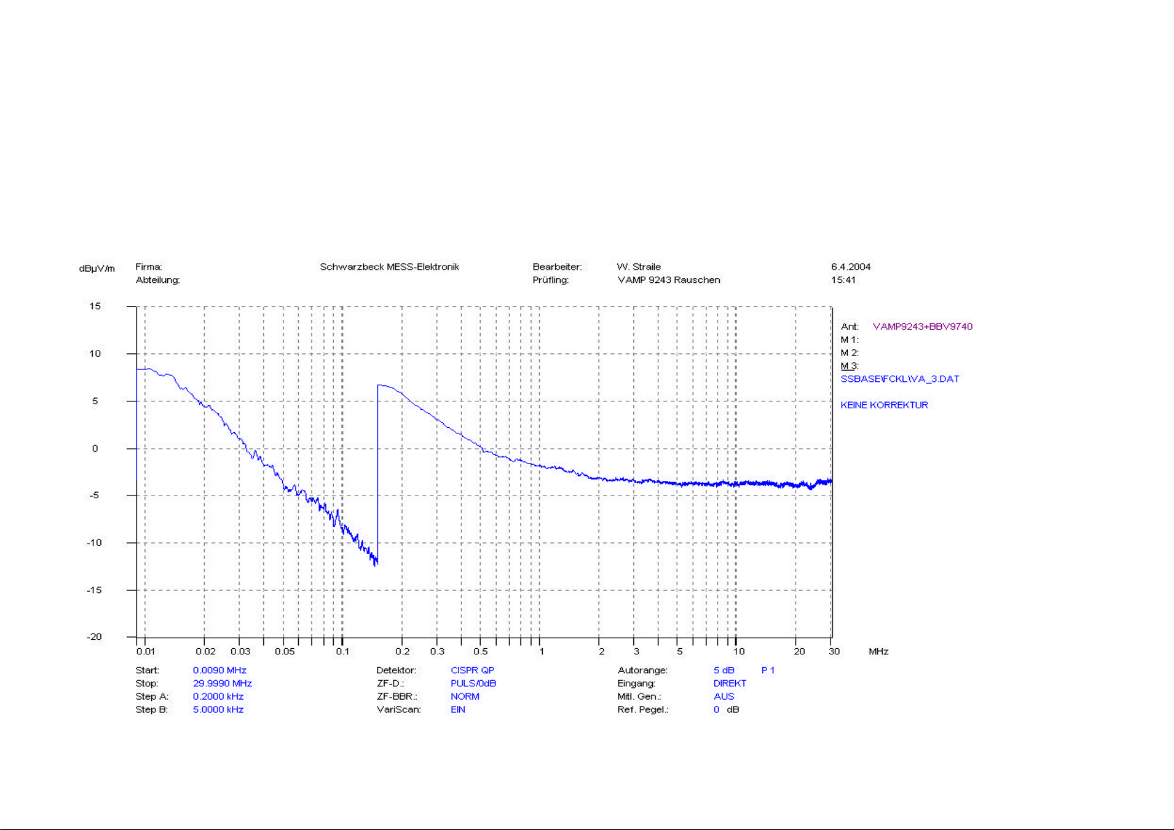
dern. Zu beachten ist, daß das Grund-
rauschen wegen der großen Empfind-
lichkeit der VAMP 9243 nur in guten
Abschirmkammern bestimmt werden
kann, weil sonst nur ein Grundstörpe-
gel gemessen wird.
Es ist ratsam, den Grundpegel mit der
Mithörkontrolle (Lautsprecher) des
Empfängers daraufhin zu überprüfen.
Reicht die Empfindlichkeit eines Emp-
fängers oder Spektrum Analysators nicht
aus, um das Grundrauschen der
VAMP 9243 anzuzeigen, kann ein ent-
sprechend empfindlicher Vorverstärker
zwischengeschaltet werden, wenn ent-
sprechend schwache Feldstärken ge-
messen werden müssen.
Dabei muß beachtet werden, daß damit
für hohe Feldstärken die Übersteue-
rungsgefahr steigt.
Because of the fact that sine wave sig-
nals give the same reading with all three
detectors, they can be measured with
the low noise average detector.
The limits for pulse spectrum are meas-
ured with Peak- or CISPR-Quasipeak
according to the standards.
Obviously these "tricks" are only impor-
tant, if limits are very close to the noise
floor.
7.4 The above considerations are only
valid for the combination of the mo-
nopole antenna and a high quality,
high sensitivity emi-receiver
(Schwarzbeck FCKL 1528).
A receiver which does not show a
higher noise reading when connected
to the VAMP 9243 cannot use the dy-
namic range.
Low quality, low sensitivity receivers
or spectrum analysers without selec-
tive preamplifiers (preselectors with
low distortion amplification) will
completely determine the noise char-
acteristics.
Even the outstanding noise and am-
plification characteristics of the VAMP
9243 cannot improve this.
The basic internal noise of the VAMP
9243 is so low that it can only be de-
termined in perfectly shielded rooms.
Otherwise parasitic signals will be
misinterpreted as basic noise.
It is good practice to use the receiver's
audio (loudspeaker) to detect the kind
of signal.
If the sensitivity of a receiver or spectrum
analyser is to poor to indicate the internal
noise of the VAMP 9243, a sensitive
preamplifier at the receiver's input will
improve the situation, when low field-
strength measurement is a must.
It has to be mentioned that overload
(intermodulation) problems with high
fieldstrength may occur.
Handbuch Manual VAMP 9243 Seite Page 8
8. Großsignalverhalten, Übersteuerung
8.1 Sättigung und Übersteuerung treten
bei hohen Eingangspegeln auf. Dabei
können sowohl eine einzige hohe Sinus-
spannung als auch ein ausgedehntes
Pulsspektrum zu Übersteuerung führen.
In der Praxis sind die Kombinationsmög-
lichkeiten unübersehbar.
Während bei einer einzigen Sinusspan-
nung schon der hohe Meßwert am
Empfänger auf eine Übersteuerungsge-
fahr hinweist, ist dies bei Breitbandspek-
tren schwierig, da sie meist nicht bei ei-
ner bestimmten Frequenz zu sehr hoher
Anzeige führen.
Übersteuerung kann sowohl zu Minder-
als auch zu Mehranzeige führen.
Während die Kompression einer Sinus-
spannung auf ihrer Grundfrequenz eine
Minderanzeige bedeutet, führt die Ober-
wellenbildung zur Mehranzeige auf ande-
ren Frequenzen.
8.2 Für Messungen im Bereich großer
Feldstärken empfehlen wir den optiona-
len 20 dB Vorsteckteiler.
Dieser wird direkt am Fuß des Stabes
eingefügt und reduziert den Spannungs-
pegel vor dem Verstärker.
Da der Verstärker als einzige aktive
Stufe allein für eventuelle Intermodulati-
on verantwortlich ist, muß die Dämpfung
davor
konzentriert werden.
Eine Dämpfung hinter dem Verstärker
reduziert die Verstärkung ebenfalls, hat
aber keinerlei positive Auswirkung auf
das Großsignalverhalten.
Breitbandige Geräte sind wegen fehlen-
der Frequenzselektion grundsätzlich an-
fälliger für Großsignalprobleme.
Das gilt für den Stabverstärker ebenso
wie für den Meßempfänger.
Weniger geeignete Empfänger oder
Spektrum-Analysatoren ohne Vorse-
lektion können von Breitband-spektren
überfordert werden.
8. Large signal handling, Overload
8.1 Saturation and overload occurs with
high input levels. One strong single sine
wave signal or extended pulse spectrum
can be the cause of overload. Virtually all
combinations occur in everyday meas-
urement.With only one single sine wave
signal present on the receiver's input, a
high reading shows very clearly that
there may be an overload. This is more
difficult with broad-band pulse spectrum,
because most often there is no ex-
tremely high reading on a specific fre-
quency. Overload can lead to both too
high or too low reading.
On one hand, compression of a sine
wave signal will lead to a lower reading,
on the other hand harmonics will be gen-
erated which lead to a higher reading on
higher frequencies.
8.2 For high fieldstrength measurement
we recommend the optional 20 dB plug-
in attenuator.
It is inserted directly at the foot of the rod
and reduces the voltage level in front of
the amplifier's input.
Because of the fact that the amplifier as
the only active part is responsible for
potential intermodulation, attenuation
must be concentrated in front.
Attenuation behind the amplifier will re-
duce amplification too, but without any
improvement for large signal handling
capability.
Broad band circuits are generally more
vulnerable to large signal handling prob-
lems.
This is true for the rod amplifier as well
as for the emi-receiver.
Low quality receivers or spectrum-
analysers without preselectors may be
overloaded by broad band spectrum.
Handbuch Manual VAMP 9243 Seite Page 9
9. Eigenrauschen der VAMP 9243
Das Eigenrauschen wurde mit einem Störmessempfänger FCKL 1528 aufgezeichnet. Im Fre-
quenzbereich 9 kHz - 150 kHz beträgt die Bandbreite 200 Hz, im Bereich 150 kHz - 30 MHz be-
trägt sie 9 kHz. Dadurch ergibt sich der "Sprung" bei 150 kHz. Das sehr niedrige Eigenrauschen
der VAMP 9243 wurde mit dem Verstärker BBV 9740 um 20 dB verstärkt.
Die Wandlungsmaße wurden zu -10 dB zusammengefasst.
Auf der Y-Achse ergibt sich damit direkt der "Rauschfeldstärkepegel" in dBµV/m.
9.1 Messung mit dem Quasipeak-Detektor
9. Internal noise of the VAMP 9243
The internal noise was recorded with the emi-receiver FCKL 1528. The bandwidth is 200 Hz in
the frequency range 9 kHz - 150 kHz and 9 kHz from 150 kHz - 30 MHz.
This is the reason for the level difference at 150 kHz.
The extremely low noise of the VAMP 9243 was amplified by 20 dB using the amplifier BBV
9740. The conversion factors are combined to -10 dB.
The Y-axis of the diagram shows the "fieldstrength-level" in dBµV caused by the VAMP 9243.
9.1 Measurement with the Quasipeak-Detector
Handbuch Manual VAMP 9243 Seite Page 10
9.2 Messung mit dem Mittelwert-Detektor 9.2 Measurement with the Average-Detector
Handbuch Manual VAMP 9243 Seite Page 11
9.3 Messung mit dem Spitzenwert-Detektor 9.3 Measurement with the Peak-Detector
Handbuch Manual VAMP 9243 Seite Page 12
10. Akku 10. Battery
Die Antenne verfügt über 8 Stück NiMH-
Akkuzellen a 1,2 V/1100 mAh und arbeitet
mit einer nominellen Betriebsspannung von
9,6 Volt.
Die Akkus sind in einer separaten Kammer
des Gehäuses untergebracht und daher voll
abgeschirmt.
Irgendwelche Einstreuungen oder Beein-
flussungen von außen sind daher unmög-
lich.
Bei einer durchschnittlichen Stromaufnahme
von <20 mA wird unter optimalen Bedingun-
gen eine typische Betriebssdauer von 50
Stunden erreicht.
Die Reserveanzeige warnt schon relativ
bald, so daß noch ausreichend Restzeit zur
Beendigung der Messung verbleibt.
Akkus dieser Bauart haben einen so kleinen
Innenwiderstand, daß sie sich bei einem
Kurzschluß innerhalb kürzester Zeit so stark
erhitzen, das durch Abschmelzen der Isola-
tion zwischen den Zellen dauerhafte Kurz-
schlüsse entstehen, was zu noch größerer
Wärmeentwicklung führt.
Der Akkusatz ist durch eine Schmelzsiche-
rung geschützt.
Sind jedoch erst einmal Kurzschlüsse zwi-
schen den Zellen entstanden, so nützt dies
nichts mehr und eine Zerstörung der Anten-
ne ist die Folge.
Die Antenne darf daher keinesfalls geöff-
net oder mit ungeeigneten Mitteln gela-
den werden.
Ein Kurzschluß des Ladeanschlusses muß
unbedingt vermieden werden.
Das optionale Ladegerät ACS 410
(Ansmann) eignet sich sehr gut, da es eine
intelligente Ladeschaltung enthält.
Die Erwärmung des Gehäuses während des
Ladevorganges ist normal.
Ladebuchse:
Innenleiter: PLUS
Außenleiter: MINUS (MASSE)
The antenna contains 8 NiMH-cells with
1,2 V/1100 mAh each resulting in a volt-
age of 9,6 Volts (nom.).
The batteries are built in a separate
shielded box inside of the cabinet. Any
stray coupling or other effects from out-
side are avoided.
A typical current consumption of <20 mA
leads to a typical operation time of 50
hours under optimum conditions.
Under these circumstances the reserve
indication can occur very much on the
safe side, providing sufficient time to
complete the measurement.
Batteries of this kind have a very low re-
sistance. After a short current they will
heat up in seconds. Burning out of the in-
sulating material between the cells leads
to permanent inner short circuit with even
more heat.
The battery is protected by a fuse. But
once a short circuit between cells is es-
tablished, the fuse cannot prevent severe
damage to the antenna.
For this reason never open the an-
tenna or charge it with inappropriate
charging equipment.
Avoid short circuits to the charging con-
nector.
The optional charger ACS 410
(Ansmann) is a good choice because of
the intelligent charging.
The cabinet may warm up while charging.
This is normal.
Charging Connector:
Inner conductor: PLUS
Outer conductor: MINUS (GROUND)
Handbuch Manual VAMP 9243 Seite Page 13
SCHWARZBECK MESS - ELEKTRONIK
An der Klinge 29 D-69250 Schönau Tel.: 06228/1001 Fax.: (49)6228/1003
Monopolantenne bei homogenen Fernfeldbedingungen
-9
-8
-7
-6
-5
-4
-3
-2
-1
0
00.2 0.4 0.6 0.8 11.2 1.4 1.6 1.8 2
Correction of Antenna Factor [dB]
Height of 0.6 x 0.6 m Groundplane above Ground [m]
1 m Rod Antenna
'afh.asc'
Höheneinfluß bei Stabantennen Height Influence of Rod Antennas
In homogenen Feldern zeigen Staban-
tennen im Gegensatz zu symmetri-
schen, dipolartigen Antennen eine star-
ke Abhängigkeit der Feldstärkemeßwer-
te von der Höhe. Die Ursache hierfür
liegt in der Stromverteilung begründet,
die sich in Anlehnung an die Leitung-
stheorie auf dem Stab und dem vertika-
len Teil des Koaxialkabels einstellt. Bei
den betrachteten Frequenzen unterhalb
von ca. 10 MHz ist die Stablänge von 1
m stets kurz gegen die Wellenlänge (λ≥
30 m), sodaß das Strommaximum am
Boden auftritt, während das Maximum
der Spannungsverteilung am oberen
Ende des Stabes zu finden ist. Durch
die sehr hochohmige Fußpunktimpe-
danz der Stabantenne wird 1 m (d.h.
genau die Stablänge) unterhalb des
Spannungsmaximums die Spannung
gemessen und dem Messempfänger
zugeführt.
In contrast to dipole-like antennas
Vertical Active Rod Antennas exhibit
a strong height influence of field-
strength indication in homogeneous
fields. The reason for the height de-
pendence is the current distribution
along the vertical part of the an-
tenna, which consists of the rod it-
self and the connected coaxial ca-
ble. The current distribution charac-
teristics on the rod is similar to the
transmission line theory. At fre-
quencies below approx. 10 MHz the
rod length of 1 m is always short
compared to the wavelength (λ≥30
m), therefore the current maximum
is at the ground, the voltage maxi-
mum is at the top of the rod. Since
active rod antennas have a very
high input impedance, the voltage is
measured at a height which is 1 m
below the top of the rod.
Handbuch Manual VAMP 9243 Seite Page 14
Bei praktischen Messungen ergeben
sich Änderungen von ca. 16 dB bei 153
kHz, wenn die Groundplane der aktiven
Stabantenne vom Boden bis auf 6 m
Höhe gebracht wird. Im unteren Höhen-
bereich bis etwa 2 m Groundplanehöhe
läßt sich auch in großen Streifenleitern
die gleiche Höhenabhängigkeit wie im
homogenen Fernfeld nachweisen. Erst
wenn die Spitze des Stabes in unmittel-
bare Nähe des Septums der Streifenlei-
tung kommt, ist eine verstärkte kapaziti-
ve Kopplung vorhanden.
Measurements have shown a
change of fieldstrength indication of
16 dB at 153 kHz in cases when the
rod antenna groundplane height
was elevated from 0 m to 6 m
height. The same height depend-
ence as under free space conditions
can be found with fields generated
in large striplines. Only a slight de-
viation caused by capacitive cou-
pling is noticeable in cases when
the rod tip comes very close to the
upper conductor of the stripline.
Handbuch Manual VAMP 9243 Seite Page 15
SCHWARZBECK MESS - ELEKTRONIK
An der Klinge 29 D-69250 Schönau Tel.: 06228/1001 Fax.: (49)6228/1003
Höheneinfluß bei Stabantennen Height Influence of Rod Antennas
Die Abbildung zeigt die Stabantenne
und die zugehörigen Strom- und Span-
nungsverteilungen bei tiefen Frequen-
zen bis ca. 10 MHz (λ>> Stablänge).
Die Lage des hochohmigen Span-
nungsabgriffs ist jeweils durch die bei-
den Pfeile gekennzeichnet.
The drawing shows the active rod
antenna mounted at different
heights and the related current and
voltage distribution for frequencies
below 10 MHz (λ>> Rod Length).
The location of the high-impedance
voltage pickup is indicated with two
arrows.
Die Feldstärkeanzeige hängt also nicht
nur von der Länge des Stabes selbst
ab, sondern auch von der Aufstellungs-
höhe über Grund. In der Literatur wird
teilweise der Begriff "effektive Höhe"
verwendet, wobei eine Kombination aus
Stablänge und Groundplanehöhe wirk-
sam wird.
The fieldstrength indication is not
only depending on the rod length it-
self, but also on the voltage pickup
height above ground. In the litera-
ture sometimes the expression
"effective height" in conjunction with
rod antennas is used. In case of
elevated antennas the effective
height is a combination of rod length
and groundplane height.
Bei den meisten Anwendungen (CISPR
25, MIL STD 461) wird die Groundplane
der Stabantenne mit der Wand der
Schirmkabine leitfähig verbunden, dies
entspricht dann dem Fall "Groundplane-
Höhe 0 m".
The groundplane is connected to
the wall of the shielded room for
most applications (e.g. CISPR 25,
MIL STD 461), which corresponds
to a groundplane height of 0 m.
Handbuch Manual VAMP 9243 Seite Page 16
SCHWARZBECK MESS - ELEKTRONIK
An der Klinge 29 D-69250 Schönau Tel.: 06228/1001 Fax.: (49)6228/1003
Kalibrierung Calibration
Die Kalibrierung der VAMP 9243 kann
mit verschiedenen Verfahren durchge-
führt werden:
The calibration of the VAMP 9243
Monopole antenna can be perfor-
med with different methods:
1. Kapazitätsnachbildung des Stabes
mit Netzwerk aus Widerständen und
Kondensatoren.
1. The self- and shunt capacitance
of the rod is simulated by a circuit of
resistors and capacitors (dummy
rod).
2. Vergleich der Stabantennen-
Messwerte mit E-Feldstärken, die mit
kalibrierten Dipolartigen Antennen ge-
messen wurde. Hierzu eignen sich ins-
besondere aktive Bikonusantennen mit
kleinen Abmessungen (z.B. EFS 9218
oder EFS 9219).
2. The measured fieldstrength is
compared to fieldstrength measu-
rements obtained with calibrated di-
pole-like antennas. Especially acti-
ve biconical antennas like EFS 9218
or EFS 9219 are suitable for this
application because of their small
dimensions.
3. Messung der magnetischen Feldstär-
ke mit kalibrierter Rahmenantenne und
Umrechnung in fiktive Elektrische Feld-
stärke (nur bei ungestörten Fernfeldbe-
dingungen möglich)
3. Measurement of the magnetic
fieldstrength and conversion into
fictitious electrical fieldstrength (only
applicable for undisturbed farfield
conditions)
Um die Verfahren 2. und 3. anwenden
zu können, wird die VAMP 9243 bei ei-
ner Höhe von 1.5 m kalibriert. Die Mit-
telpunkte der Vergleichsantennen (in
der Abbildung als H gekennzeichnet)
sind auf Höhe des Fußpunktes der
Stabantenne (Groundplane, GH)
The field-calibration of VAMP 9243
is made at a height of 1.5 m above
ground. The center points of the
comparison antennas mentioned
under 2. and 3. are at the same
height (marked as H in the drawing)
as the groundplane (GH) of the rod
antenna.
Handbuch Manual VAMP 9243 Seite Page 17
12. Vorsteckteiler 20 dB (Option)
Bedingt durch den Verstärker hat die
VAMP 9243 eine obere Aussteue-
rungsgrenze. Wird diese erreicht, so
treten Signalverzerrungen
(Intermodulation) auf. Der Beginn dieser
Aussteuerungsgrenze ist typisch 1 V/m,
bezogen auf ein einziges Sinussignal.
Im Gegensatz zu sehr stark gegenge-
koppelten Schaltungen ist der Begren-
zungseinsatz bei der VAMP 9243 relativ
"weich". Wenn also nur ein starkes Si-
gnal gemessen werden soll, steht noch
eine Reserve von etwa 10 dB zur Ver-
fügung.
Sind mehrere Signale vorhanden, so
müssen sich diese den Verstärker
"teilen", es bleibt also für das einzelne
Signal weniger Aussteuerung übrig.
Selbst wenn das zu messende Signal
klein ist, kann ein frequenzmäßig weitab
liegendes starkes Signal den Verstärker
zu stark aussteuern.
Bitte beachten Sie dazu Kapitel 8.
Da durch das niedrige Eigenrauschen
der VAMP 9243 die Empfindlichkeit
auch mit dem Vorsteckteiler in den
meisten Fällen ausreicht, sollte dieser
schon bei Feldstärkepegeln von
>100 dBµV/m in Betracht gezogen wer-
den.
Einstecken des Teilers
Zuerst mit den Händen das Masseblech
berühren (Entladung).
Den Stab durch Linksdrehung etwas
lockern.
Den Massestecker des Vorsteckteilers
in die Massebuchse der VAMP 9243
einstecken.
Durch Drehung kann nun die Lasche
des Teilers unterhalb des Stabes einge-
fahren werden.
Durch Rechtsdrehung des Stabes wird
nun die Verbindung hergestellt.
Wandlungsmaß (Antennenfaktor)
Das Wandlungsmaß der VAMP 9243
ohne Vorsteckteiler beträgt +10 dB/m.
Mit dem Vorsteckteiler beträgt es
+30 dB/m. Zu dem am Empfänger ab-
gelesenen Spannungspegel in dBµVm
wird also 30 dB/m addiert, um den
Feldstärkepegel in dBµV/m zu erhalten.
12. Input Attenuator 20 dB (Option)
Caused by the internal amplifier the
VAMP 9243 has a maximum field-
strength limit.
When this limit is reached signal distor-
tion (intermodulation) may occur. This
limit begins at typically 1 V/m for one
single sine wave signal. Unlike circuits
with a high open loop amplification and
strong negative feedback the VAMP
9243 is a "soft limiter ".
When there is only one strong signal to
measure, there is a 10 dB margin avail-
able before saturation occurs.
When more signals are present at one
time they have to "share" the amplifier
which results in less performance for
each of the signals.
Even a weak signal may be influenced
by a strong signal on a far away fre-
quency.
Please read chapter 8.
Due to the low noise level of the VAMP
9243 the sensitivity even with the input
attenuator is good enough in many
cases. So think about using the at-
tenuator even with fieldstrength levels
from >100 dBµV/m on.
Plug in
First discharge your body by touching
the metal ground.
Loosen the rod by turning it some turns
ccw.
Plug the ground pin of the attenuator
into the ground connector near the rod.
Turn the attenuator until the metal strap
fits under the rod.
Turn the rod cw. to fix the connection.
Conversion factor (Antenna factor)
The conversion factor of the VAMP
9243 without input attenuator is
+10 dB/m. With plugged in attenuator it
is +30 dB/m.
Read the receiver measurement in
dBµVm and add 30 dB/m to get the
fieldstrength level in dBµV/m.

Other Schwarzbeck Antenna manuals

Schwarzbeck FMZB 1512 User manual

Schwarzbeck

Schwarzbeck FMZB 1512 User manual

Schwarzbeck HXYZ 9170 User manual

Schwarzbeck

Schwarzbeck HXYZ 9170 User manual

Schwarzbeck AM 9104 User manual

Schwarzbeck

Schwarzbeck AM 9104 User manual

Schwarzbeck XSLP 9142 User manual

Schwarzbeck

Schwarzbeck XSLP 9142 User manual

Schwarzbeck EFS 9219 User manual

Schwarzbeck

Schwarzbeck EFS 9219 User manual

Popular Antenna manuals by other brands

Panorama Antennas BSM-6-60 installation instructions

Panorama Antennas

Panorama Antennas BSM-6-60 installation instructions

Novatel T2050 user manual

Novatel

Novatel T2050 user manual

EchoStar Hughes 9211 user guide

EchoStar

EchoStar Hughes 9211 user guide

zBoost CANT-0042 Installation

zBoost

zBoost CANT-0042 Installation

RFI Mopole CD63-71-73 Series Installation

RFI

RFI Mopole CD63-71-73 Series Installation

Portable Rotation 12PRSAT-MAG Installation and operating manual

Portable Rotation

Portable Rotation 12PRSAT-MAG Installation and operating manual

RCA ANT1080E quick start guide

RCA

RCA ANT1080E quick start guide

TRENDnet TEW-AI86DB Specifications

TRENDnet

TRENDnet TEW-AI86DB Specifications

halo & SON CoFlex3200 user manual

halo & SON

halo & SON CoFlex3200 user manual

H3C ANT-2506V-M6-E installation guide

H3C

H3C ANT-2506V-M6-E installation guide

Siemens SIMATIC NET ANT895-6ML operating instructions

Siemens

Siemens SIMATIC NET ANT895-6ML operating instructions

A.H. Systems SAS-521-4 Operation manual

A.H. Systems

A.H. Systems SAS-521-4 Operation manual

Poynting PowerfulSignal PUCK-1 user guide

Poynting

Poynting PowerfulSignal PUCK-1 user guide

Hirschmann AUTA 6000 KE 1/11 user manual

Hirschmann

Hirschmann AUTA 6000 KE 1/11 user manual

Alfa Network UBDo-nt user manual

Alfa Network

Alfa Network UBDo-nt user manual

Sennheiser A 1031 U user manual

Sennheiser

Sennheiser A 1031 U user manual

Ubiquiti AirMax AMY-9M16 Quck Start Gude

Ubiquiti

Ubiquiti AirMax AMY-9M16 Quck Start Gude

Huawei AAU3902 Hardware description

Huawei

Huawei AAU3902 Hardware description

manuals.online logo
manuals.online logoBrands
  • About & Mission
  • Contact us
  • Privacy Policy
  • Terms and Conditions

Copyright 2025 Manuals.Online. All Rights Reserved.