schweisskraft VarioProtect XL-W TC User manual

VarioProtect XL-W TC
Operating Instructions
VarioProtect XL-W TC
VARIO PROTECT
Automatic Welding Helmet

2 VarioProtect XL-W TC | Version 1.07 | EN
Imprint
Product identification
Automatic Welding Helmet Item number
VarioProtect XL-W TC 1651000
Manufacturer
Stürmer Maschinen GmbH
Dr.-Robert-Pfleger-Str. 26
D-96103 Hallstadt
Fax: 0049 (0) 951 96555 - 55
E-Mail: [email protected]
Internet: www.schweisskraft.de
Indications regarding the operating instructions
Original instructions
Edition: 11.10.2022
Version: 1.07
Language: English
Author: RL
Indications regarding the copyright
Copyright © 2022 Stuermer Maschinen GmbH,
Hallstadt, Germany.
Subject to technical modifications and error.
Content
1 Introduction ......................................................3
1.1 Copyright ............................................................ 3
1.2 Customer service................................................ 3
1.3 Limitation of liability............................................. 3
2 Safety ................................................................3
2.1 Symbol explanation ............................................ 3
2.2 Safety regulations............................................... 4
2.3 Safety data sheets.............................................. 4
3 Intended use.....................................................5
3.1 Reasonably foreseeable misuse......................... 5
3.2 Residual risks ..................................................... 5
4 Technical Data..................................................5
5 Description .......................................................6
5.1 Wearing parts ..................................................... 6
6 Transport, Packaging, Storage.......................6
6.1 Transport ............................................................ 6
6.2 Packaging........................................................... 6
6.3 Storage ............................................................... 6
7 Product features and Adjustment options ....7
7.1 Selection of the delay time.................................. 7
7.2 Setting the sensitivity.......................................... 7
7.3 Setting the protection level range ....................... 7
7.4 Adjustment possibilities of the headbands.......... 8
8 Notes before Commissioning.........................8
9 Automatic Welding protection filter...............8
10 Common problems and solutions................9
11 Color Table (Recommended shade
numbers) ......................................................10
12 Meaning of the Marking...............................10
13 Care, Maintenance and Repair ...................11
13.1 Care by cleaning............................................ 11
13.2 Replacement of the front pane of the helmet.... 11
13.3 Maintenance/Repair....................................... 11
14 Disposal, Recycling of used Devices ........12
14.1 Decommissioning .......................................... 12
14.2 Disposal of the new equipment packaging .... 12
15 Spare Parts...................................................12
15.1 Ordering spare parts...................................... 12
15.2 Spare parts drawing....................................... 13
16 Electrical Circuit Diagram ...........................14
17 EC - Declaration of Conformity...................15

Introduction
VarioProtect XL-W TC | Version 1.07 | EN 3
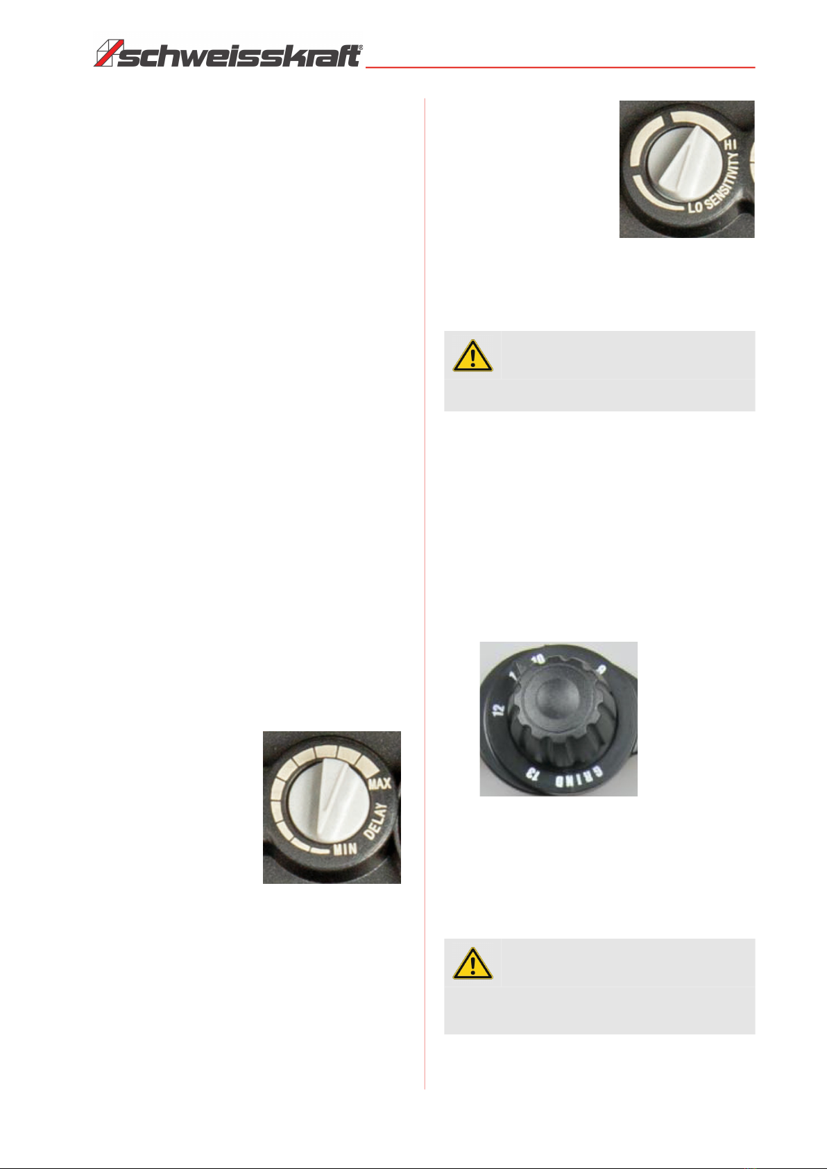
1 Introduction
You have made a good choice by purchasing the
Schweisskraft welding helmet.
Read the operating instructions carefully before
using the welding helmet.
These provide information on the proper start-up, the in-
tended use and the safe and efficient operation and
maintenance of the welding helmet.
The operating manual is an integral part of the welding
helmet. They must always be kept at the place of use of
the welding helmet. In addition, the local accident pre-
vention regulations and general safety regulations for the
area of use of the welding helmet apply.
Illustrations in these operating instructions are for basic
understanding and may deviate from the actual design.
1.1 Copyright
The contents of these instructions are protected by copy-
right and are the sole property of Stürmer Maschinen
GmbH. Their use is permitted within the scope of the use
of the welding helmet. Any use beyond this is not permit-
ted without the written approval of the manufacturer.
Passing on as well as duplication of this document, utili-
zation and communication of its contents are forbidden,
as far as not expressly permitted. Violations will result in
liability for damages.
We register trademarks, patents and design rights for the
protection of our products,
patent and design rights, insofar as this is possible in in-
dividual cases. We emphatically oppose any infringe-
ment of our intellectual property.
1.2 Customer service
Please contact your dealer if you have questions con-
cerning your Automatic Welding Helmet or if you need
technical advice. They will help you with specialist infor-
mation and expert advice.
Germany:
Stürmer Maschinen GmbH
Dr.-Robert-Pfleger-Str. 26
D-96103 Hallstadt
Repair service:
Fax: 0049 (0) 951 96555-111
Email: service@stuermer-maschinen.de
Spare part orders:
Fax: 0049 (0) 951 96555-119
Email: ersatzteile@stuermer-maschinen.de
We are always interested in valuable experience and
knowledge gained from using the application-which then
could be shared and be valuable to develop our products
even further.
1.3 Limitation of liability
All information and notes in these operating instructions
were summarised while taking applicable standards and
rules, the state-of-the-art technology and our long-term
knowledge and experiences into consideration.
In the following cases the manufacturer is not liable for
damages:
- Non-observance of the operating instructions,
- Inappropriate use
- Use of untrained staff,
- Unauthorised modifications
- Technical changes,
- Use of not allowed spare parts.
The actual scope of delivery may deviate from the expla-
nations and presentations described here in case of spe-
cial models, when using additional ordering options or
due to latest technical modifications.
The obligations agreed in the delivery contract, the gen-
eral terms and conditions as well as the delivery condi-
tions of the manufacturer and the legal regulations at the
time of the conclusion of the contract are applicable.
2 Safety
This section provides an overview of all important safety
packages for the protection of operating personnel as
well as for safe and fault-free operation. Other task-
based safety notes are included in the paragraphs of the
individual phases of life.
2.1 Symbol explanation
Safety instructions
The safety notes in these operating instructions are high-
lighted by symbols. The safety notes are introduced by
signal words which express the concern of the risk.

4 VarioProtect XL-W TC | Version 1.07 | EN
Safety
Tips and recommendations
It is necessary to observe the safety notes written in
these operating instructions in order to reduce the risk of
personal injuries and damages to property.
2.2 Safety regulations
- This welding helmet is not suitable for use in laser
welding with gas and/or oxygen and acetylene wel-
ding or cutting processes.
- Check the welding helmet for visible damage and
defects before use. Repair defects and damage im-
mediately.
- Do not use the welding helmet in wet environments,
rain, etc.
- Only use original spare parts and accessories.
- Check the helmet for light transmission
- Never place this welding helmet or filter on a hot sur-
face.
- Protect the filter from dirt.
- Never open the welding filter.
- Before using the wwelding helmet, make sure that
the operating mode is set correctly. - „Welding“ or
„Grinding“.
- This welding helmet does not protect you from ex-
plosives or corrosive liquids.
- Do not make any changes, not on the welding filter
or the welding helmet, unless it is explicitly stated in
this manual.
- If the viewing window does not darken immediately
after the welding arc is ignited, welding must be
stopped immediately. Contact your supervisor or
your dealer immediately.
- Do not use any solvents on the window or helmet.
- Only use the welding helmet at temperatures bet-
ween -5 °C and +50 °C.
- Store the helmet at temperatures between -20 °C
and +70 °C.
- Protect the viewing window from liquid and dirt.
- Clean the viewing window regularly and do not use
strong cleaning agents.
- Keep the sensors and solar panel clean. Use a
clean, lint-free cloth for cleaning.
- Replace the sensors if they are damaged.
- Replace the protective lens regularly or if they are
scratched or damaged.
- Set the correct protection level before using the helmet.
- Adjust the headband so that the helmet sits as low
as possible on your head and close to your face. Ad-
just the angle of the helmet in the lowered position
by turning the adjustable limiting disc.
- Select the necessary position of the welding/grinding
switch before welding.
2.3 Safety data sheets
Safety data sheets for hazardous materials can be obtai-
ned from your specialist dealer or by phone: +49 (0)951/
96555-0. Specialist dealers can find safety data sheets
in the download area of the partner portal.
DANGER!
This combination of symbol and signal words indi-
cates an imminently dangerous situation which may
lead to death or severe injury if not avoided.
WARNING!
This combination of symbol and signal words indi-
cates a potentially dangerous situation which may
lead to death or severe injury if not avoided.
CAUTION!
This combination of symbol and signal words indi-
cates a potentially dangerous situation which may
lead to slight or minor injury if not avoided.
ATTENTION
This combination of symbol and signal words indi-
cates a possibly dangerous situation which may lead
to property and environmental damages if they are
not avoided.
NOTE!
This combination of symbol and signal words indi-
cates a potentially dangerous situation which may
lead to material or environmental damage if not
avoided.
Tips and recommendations
This symbol highlights useful tips and recommenda-
tions as well as information for an efficient and trou-
ble-free operation.
ATTENTION!
Serious injury can occur if the user ignores the war-
nings and/or refuses to follow the instructions in the
operating manual!
ATTENTION!
Before use make sure the protection films on both
inside & outside protection lens are removed (if availa-
ble).

Intended use
VarioProtect XL-W TC | Version 1.07 | EN 5
3 Intended use
The Automatic Welding Helmet VarioProtect XL-W TC is
exclusively designed to protect the eyes of welders from
harmful radiation in the visible, ultraviolet (UV) and infra-
red (IR) range during certain arc and gas welding
processes, shielded arc welding and plasma cutting, as
well as to protect the eyes and face from welding sparks
and spatter.
The helmet can also be used for grinding.
The use of the welding helmet for laser welding is prohi-
bited.
Any use other than that described in these operating in-
structions is not permitted. Intended use also includes
compliance with all the information in these instructions.
Any use beyond the intended use or any other use is
considered misuse.
3.1 Reasonably foreseeable misuse
Any use beyond or different from the intended use is
considered misuse.
Possible misuses can be:
- Use in areas with hazardous substances, explosion
risk or fire hazard.
- Use of the welding helmet during welding work in the
"Grinding" (GRIND) operating mode.
- Failure to observe signs of wear and damage.
- Bypassing or modifying the protective devices.
- Non-observance of the maintenance instructions.
- Installation of spare parts and use of accessories
and equipment not approved by the manufacturer.
- Deliberate or careless handling of the Automatic
Welding Helmet during operation.
Misuse of the Automatic Welding Helmet can lead to dan-
gerous situations.
Stürmer Maschinen GmbH accepts no liability for design
and technical modifications to the Automatic Welding Hel-
met.
Claims of any kind for damage due to improper use are ex-
cluded.
3.2 Residual risks
Even if all safety regulations are observed and the ma-
chine is used in accordance with the regulations, there
are still residual risks, which are listed below.
- Eye damage if the filter cassette is defective.
- Respiratory damage when inhaling welding fumes
due to insufficient extraction.
4 Technical Data
Technical Data VarioProtect XL-W TC
Dimensions of cas-
sette
110 x 90 x 8 mm
Viewing window (WxH) 100 x 49 mm
Power supply Solar cells + Replaceable
battery
Type of battery Li-Mn (CR2032)
Class 1/1/1/2
UV/IR-Protection Permanent DIN 16
Light level Protection level 4
Dark protection level DIN 9 - 13
Security level in case
of failure
Protection level 4
Reaction time from
light to dark
0,1 ms.
Fading time from dark
to light
0,15 sec. - 0,8 sec.
steplessly adjustable
Sensitivity steplessly adjustable
Lens power 4,8 mm
Material Nylon
Working temperature -5°C - +55°C
Storage temperature -20°C - +70°C
Dimensions (LxWxH) 238 x 174 x 334 mm
Weight 314 g

6 VarioProtect XL-W TC | Version 1.07 | EN
Description
5 Description
Fig. 1: Description of the VarioProtect XL-W TC
1 Fixing element front viewing window
2 Setting protection level/grinding mode (GRIND)
3 Headband adjustment and tilting
4 Viewing window (SWM 1 F CE)
5 Cassette and inner pane
6 Marking ot the welding helmet („SWM 175 F CE“)
7 Battery cover with LED display (LOW BATT.)
8 Battery cover with LED display (LOW BATT.)
9
Marking of the cassette (4/9-13 SWM 1/1/1/2/379 CE)
10 Setting the sensitivity (SENSITIVITY)
11 Setting the brightening time (DELAY)
5.1 Wearing parts
6 Transport, Packaging, Storage
6.1 Transport
Check the welding helmet on delivery for any visible trans-
portation damage. If you notice any damage to the device
please report this immediately to the carrier or dealer.
6.2 Packaging
All used packaging materials and packaging aids are re-
cyclable and should be taken to a materials recycling de-
pot to be disposed of.
The delivery packaging is made of cardboard, so please
dispose carefully by having it chopped up and given to
the recycling collection
The film is made of polyethylene (PE) and the cushioned
parts of polystyrene (PS). Deliver these substances to a
collection point for recyclable materials or to the waste
disposal company which looks after your region.
6.3 Storage
The welding helmet must be stored thoroughly cleaned
in a dry, clean environment at temperatures ranging from
-20 °C to +70 °C.
The solar cells of the filter should be stored in the dark or
not exposed to light.
2
3
5
4
1
6
2
5
7
8
9
11
10
Description Item
number
Quantities /
price unit
Con-
tent
Outer viewing pane
1662155 VPE 10
Inner viewing pane
1662156 VPE 10
Welding helmet
housing
1662157
Piece 1
Forehead sweat-
band
1662112
Piece 1
Complete head-
band
1662102
Piece 1
Battery / Button cell
1662107
Piece 1
Filter cassette
1662158
Piece 1

Product features and Adjustment options
VarioProtect XL-W TC | Version 1.07 | EN 7
7 Product features and Adjustment op-
tions
The shape of the helmet relieves the head and neck of
the welder, so the user feels more comfortable while
working.
Before welding, the filter is transparent and clear, which
allows a clear view to the workpiece.
As soon as an arc is ignited, the two photo sensors on
the welding filter react and darken the view in less than
0.1 milli-seconds.
As soon as welding is finished, the filter automatically
brightens.
At low ambient temperatures, the reaction of the liquid
crystal in the automatic welding filter is slower. However,
the protective functions are not affected.
The lifetime of the welding helmet depends on various
factors, such as usage, cleaning, storage and main-
tenance. We recommend a usage period of five years
with regular inspections and replacement of tels in case
of damage.
7.1 Selection of the delay time
When welding is interrupted, the viewing window auto-
matically changes from dark to light, but with a preset de-
lay so that each time the bright light from the afterglow
on the workpiece is dimmed. The delay or reaction time
can be set between 0.15 and 0.8 seconds as required
using the DELAY control on the inside of the helmet.
Fig. 2: Setting the delay time
7.2 Setting the sensitivity
Switching the filter to darkening can be adjusted with the
"SENSITIVITY" control on the filter cassette of the hel-
met. It can be set from low (LO) to high (HI).
Fig. 3: Rotary knob for sensitivity adjustment
Set the sensitivity to the highest position before welding
and adjust it accordingly during welding if necessary.
7.3 Setting the protection level range
The protection levels (from DIN9 to DIN13) are selected
with the protection level switch on the left outside of the
helmet.
The welding filter completely protects the eyes and face
of the welder against UV and IR radiation during the wel-
ding process, even if the cassette does not darken. The
UV/IR protection is always available up to DIN 16. There-
fore the user feels safe during welding
Fig. 4: Rotary knob for protection level
Set the protection level before welding using the color ta-
ble according to the welding method used and the wel-
ding current. If the darkening is too strong or too weak,
adjust the controller slightly until the welding spot can be
seen.
ATTENTION!
Before welding is started, the operating mode switch
must be reset to a protection level for welding.
ATTENTION!
If the welding helmet is used with the wrong protec-
tion level for a longer period of time, the eyes can be
injured.

8 VarioProtect XL-W TC | Version 1.07 | EN
Notes before Commissioning
7.4 Adjustment possibilities of the headbands
Fig. 5: Headband adjustment
A Rear headband - Adjustment option with knob further
(turn counterclockwise) or tighter (turn clockwise) to
adjust the fit of the helmet looser or tighter.
To adjust, first press the knob, then turn it.
B Upper headband - Adjustment option further or tighter
in the direction of the arrow to adjust the helmet to a
suitable position.
C Side straps - Adjustment possibility symmetrically wi-
der or narrower in the direction of the arrow on both si-
des to adjust the distance of the user's eyes to the fil-
ter lens. To adjust, loosen the knobs on both sides of
the helmet, symmetrically move the helmet to the
appropriate position and tighten the knobs.
D Tilt Angle - Adjustment options to adjust the height of
the user's eyes to the filter lens and the angle of the
helmet to the user's face. To adjust, loosen the knobs
on the outside of the helmet, move the helmet to the
appropriate position and tighten the knobs.
The adjustment possibilities of the headgears provide
maximum wearing comfort.
8 Notes before Commissioning
Do not use at temperatures below -5 °C and above + 23 °C.
This product material will age and suffer damage over
time, such as bursting damage. This product may no lon-
ger provide effective protection after age-related da-
mage has occurred. Users should stop using it immedi-
ately.
This product cannot be used for welding overhead.
When the helmet is used for overhead welding or over-
head cutting, the molten metal droplet may pass through
the filter and cause injury to the welder.
If the filter is defective, the user must stop using it imme-
diately. Spray slag can damage the surface of the filter
and the user's skin or even cause more serious acci-
dents.
This product has a certain heat resistance and flame re-
tardant properties. However, the mask may burn or melt
if exposed to an open flame or access to high tempera-
ture objects. Please store and use properly to reduce
such risks.
The filter is an electronic product and is not waterproof.
Make sure it is dry and clean and not stored in a humid
environment.
Non-standard operation may damage the user's body.
Please check the filter before each use. As soon as the
function and appearance are no longer functional, stop
using it immediately.
Do not expose this product to the sun.
9 Automatic Welding protection filter
Marking: 4 / 9-13 SWM 1/1/1/2/379 CE
Optical characteristics:
Optical class: 1
Scattered light class: 1
Homogeneity class: 1
Angular dependence class: 2
C D
AB

Common problems and solutions
VarioProtect XL-W TC | Version 1.07 | EN 9
10 Common problems and solutions
Irregular darkening of the cassette
- The headband may be adjusted differently on both si-
des of the helmet (asymmetrical distances between
eyes and viewing window). Adjust the headband and
the distance to the viewing window again.
Automatic cassette does not darken or flickers
- Sensors dirty or solar panel covered.
--> Clean surface of the sensors.
- Outer viewing pane dirty or damaged.
--> Replace or clean the outer viewing pane.
- Sensitivity is set too low or the delay time is set too
short.
--> Set to required value.
- Unsuitable protection level set.
--> Set suitable protection level.
Automatic cassette remains darkened after comple-
tion of the welding process
- Delay time is set too long.
--> Set to required value.
Reaction time too long
- Operating temperature too low.
--> Do not use below - 5 °C.
Faults in electrical parts.
--> Replace the automatic welding filter.
Poor visibility
- Outer pane and/or inner pane and/or filter lens are dirty.
--> Check, clean or replace outer pane. Check, clean or
replace filter lens.
- Ambient light insufficient.
--> Adjust ambient light.
- Color number incorrectly set.
--> Use color tone table for correct setting
Welding helmet slips
- Headgear not correctly adjusted.
--> Adjust the headgears correctly.
WARNING!
The user must immediately remove the welding hel-
met and stop the application if the above problems
cannot be solved. Contact your dealer.
WARNING!
If the material comes into contact with the user's
skin, it could, under some circumstances, cause an
allergic reaction on the skin.

10 VarioProtect XL-W TC | Version 1.07 | EN
Color Table (Recommended shade numbers)
11 Color Table (Recommended shade numbers)
Fig. 6: Color table
12 Meaning of the Marking
Each product is marked with an appropriate protection
level (DIN5 to DIN9 and from DIN9 to DIN13). Make sure
that the correct protection level is set before starting the
welding process. The classification for eye protection is
according to DIN EN 379, other markings on the product
are in accordance with the corresponding European
standards.
Example Filter (DIN EN 379):
Fig. 7: Classification for eye protection
The safety helmet and the outer pane are marked with
identification letters indicating the protection class
against impact energy (flying parts):
Safety helmet: SWM 175 F CE
175: Norm
F: Low impact energy (45 m/s).
Outer pane (Safety pane): SWM 1 F CE
1: Optical class
F:
Low impact energy
(45 m/s);
Inner pane: SWM 1 F CE
1: Optical class
F: Low impact energy(45 m/s);
SWM: Identification of the manufacturer
CE: CE-marking

Care, Maintenance and Repair
VarioProtect XL-W TC | Version 1.07 | EN 11
The protective equipment must comply with the require-
ments for operating temperatures from -5 °C to +50 °C.
Otherwise, the eye protection device may only be used
at room temperature.
13 Care, Maintenance and Repair
13.1 Care by cleaning
Clean the welding filter and the protective screens with a
lens cleaning cloth or a clean soft cloth with a suitable
glass detergent.
Do not immerse the welding filter in water or other li-
quids. Never use abrasives, solvents or oil-based
cleaning agents.
Please clean the surface of the welding filter, sensor and
solar cells regularly.
Clean the viewing window regularly and do not use
strong cleaning agents. Keep the sensors and solar
panel clean by using a clean lint-free cloth.
13.2 Replacement of the front pane of
the helmet
Replace the outer and inner pane regularly.
Replace the outer viewing pane if it is damaged
(cracked, scratched, dirty or holey)
1. Remove the used outer pane by taking out the clamps
on the inside of the helmet and taking off the locking
pieces on the outside of the helmet.
2. Remove the outer pane and place the new pane in the
correct position.
3. Insert the locking pieces into the recesses and fasten
them to the inside of the helmet with the clamps.
Replacement of the inner pane if it is damaged
(cracked, scratched, dirty or holey)
13.3 Maintenance/Repair
If the welding helmet does not function properly, contact
a specialist dealer or our customer service. The contact
details can be found in chapter 1.2 Customer service.
CAUTION!
The mechanical strength of the helmet can only be
as strong as its weakest part.
WARNING!
Danger in case of insufficient quali-
fication of the staff!
Insufficiently qualified persons cannot estimate the
risks to the user resulting from improper repair work
on the welding helmet and expose themselves and
others to the risk of serious injury.
Have all maintenance work carried out only by quali-
fied persons.
NOTE!
After care, maintenance and repair work, check that
all covers and protective devices are properly
remounted on the welding helmet.
Damaged guards and parts must be repaired or
replaced by customer service.
ATTENTION!
Never use aggressive solvents such as acetone.
ATTENTION!
- Repairs or maintenance work may only be carried
out by qualified and trained personnel.
- Only use original spare parts.

12 VarioProtect XL-W TC | Version 1.07 | EN
Disposal, Recycling of used Devices
14 Disposal, Recycling of used Devices
Please take care in your own interest and in the interest of
the environment that all component parts of the machine
are only disposed of in the intended and permitted way.
14.1 Decommissioning
Discarded devices must be taken out of service immedi-
ately in a professional manner in order to avoid later mi-
suse and danger to the environment or persons.
- Remove batteries and accumulators, if available.
- If necessary, dismantle the welding helmet into mana-
geable and recyclable assemblies and components.
- Dispose of the components in the designated disposal
channels.
14.2 Disposal of the new equipment
packaging
All packaging materials and packaging aids used are
recyclable and must always be sent for material recy-
cling.
These components are to be disposed of separately and
in a professional manner. In case of doubt, contact the
municipal waste disposal service.
If necessary, use the services of a specialised waste dis-
posal company for processing.
15 Spare Parts
15.1 Ordering spare parts
The spare parts may be purchased with the authorised
dealer.
Indicate the following basic information for requests or
orders of spare parts:
- Type of device
- Item No.
- Position No.
- Year of construction:
- Quantity
- Required mode of dispatch (mail, freight, sea, air,
express)
- Address of dispatch
Spare part orders which do not include the above indica-
tions may not be taken into consideration. If the indica-
tions regarding the mode of dispatch are missing, the
product is dispatched at the discretion of the supplier.
You will find information regarding the device type, item
No. and year of manufacture on the type plate fixed to
the welding helmet.
Example:
The filter cassette for the welding helmet VarioProtect
XL-W TC must be ordered. The filter cassette has the
number 17 in the spare parts drawing 1.
When ordering spare parts, send a copy of the spare
parts drawing with marked component (filter cassette)
and marked item number (17) to the authorized dealer or
to the spare parts department and provide the following
information:
Device type:
VarioProtect XL-W TC
Item number: 1651000
Position number: 17
DANGER!
Danger of injury by the use of
wrong spare parts!
Dangers may result for the user and damages as well
as malfunctions may be caused by using wrong or
damaged spare parts.
- Only use original spare parts of the manufacturer or
spare parts admitted by the manufacturer.
- Always contact the manufacturer in case of uncer-
tainties.
NOTE!
The manufacturer's warranty will become null and
void if non-permissible spare parts are used.

Spare Parts
VarioProtect XL-W TC | Version 1.07 | EN 13
15.2 Spare parts drawing
The following drawing should help you to identify necessary spare parts in case of service. If necessary, send a copy of
the parts drawing with the marked components to your dealer.
Fig. 8: Spare parts VarioProtect XL-W TC
9
1 Sweatband 10 Front pane
2 Left limitation washer 11 Helmet schell (housing)
3 Adjustable washer 12 Filter cassette
4 Plain washer 13 Inner pane
5 Headband adjustable knobs 14 Locking element front pane
6 Right limitation washer 15 Clamping element
7 Adjusting screw 16 Regulation scale platelet
8 Rear adjustment knob 17 Rotary control knob (darkening level)
9 Rear headband 18 Fixing disk for rotary control knob

14 VarioProtect XL-W TC | Version 1.07 | EN
Electrical Circuit Diagram
16 Electrical Circuit Diagram
Fig. 9: Electrical circuit diagram VarioProtect XL-W TC

EC - Declaration of Conformity
VarioProtect XL-W TC | Version 1.07 | EN 15
Manufacturer/Distributor: Stürmer Maschinen GmbH
Dr.-Robert-Pfleger-Starße 26
D-96103 Hallstadt
hereby declares that the personal protective equipment (PPE) described below complies with the PPE-Regulation 2016/
425/EU and the Product Safety Directive 2001/95/EU, and is identical with the PPE that is the subject of the test perfor-
med by the accredited testing institute.
Product group: Schweisskraft®
Designation: VarioProtect XL-W TC
Product type: Automatic Welding Helmet
Item number: 1651000
Serial number *: ____________________
Year of manufacture *: 20____
* please fill in according to the information on the type plate
Relevant EU-Directives: 2014/30/EU EMC-Directive
2011/65/EU RoHS-Directive
The following harmonized standards were applied:
DIN EN 175:1997-08 Personal protection - Equipment for eye and face protection during welding
DIN EN 379:2009-07 Personal eye protection - Automatic welding filters
DIN EN 166:2002-04 Personal eye protection - Requirements
Responsible for documentation: Kilian Stürmer, Dr.-Robert-Pfleger-Str. 26, D-96103 Hallstadt
Hallstadt, 11.10.2022
______________________
Kilian Stürmer
Managing Director
Inner and outer pane Automatic welding protection filter
1000SF
Face shield (helmet)
1000SH
Certification Authority Certification Authority Certification Authority
ECS GmbH
Hüttfeldstraße 50
73430 Aalen
Identification-No. 1883
ECS GmbH
Hüttfeldstraße 50
73430 Aalen
Identification-No. 1883
ECS GmbH
Hüttfeldstraße 50
73430 Aalen
Identification-No. 1883
i
ssued EU type examination certificate.
C2320.1SWM C3170.2SWM C3171.1SWM
17 EC - Declaration of Conformity

This manual suits for next models
1
Table of contents
Other schweisskraft Motorcycle Accessories manuals
Popular Motorcycle Accessories manuals by other brands

hepco & becker
hepco & becker 5012515 00 01 manual

Mastech
Mastech BMW 310 GS Assembly instructions

hepco & becker
hepco & becker 6609515 01 05 Mounting instructions

RADE/GARAGE
RADE/GARAGE ADV windshield installation manual

SW-Motech
SW-Motech KFT.04.835.65000/B Mounting instructions

KTM Power Parts
KTM Power Parts 60812905044 quick start guide