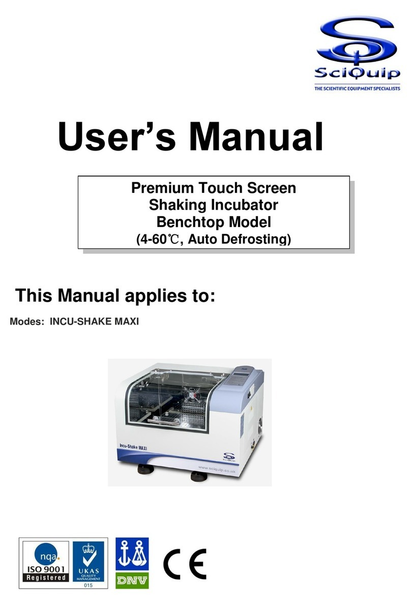
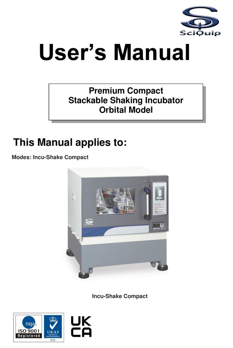
SciQuip Incu-Shake Series User manual

User’s Manual
This Manual applies to:
Modes:
Incu-Shake MINI
Incu-Shake MIDI
Incu-Shake series
Shaking Incubator

SciQuip INCU-Shake Series V2016.1.1
1
SciQuip Incu-Shake incubators have achieved a good reputation and trust among
various clients for its advanced temperature controlling technology, sound framework
design, excellent molded exterior and outstanding professional workmanship. These
products have been exported through most leading companies into European,
American and East Asian markets.
SciQuip Incu-Shake incubators have a number of advanced specifications like an
intelligent precise control of temperature and shaking speed through the standard
control panel and solid operating safety features. This large benchtop model is
available all with heavy duty orbital shaking mechanisms that provide smooth start
and quiet shaking motion under maximum load with maximum speed.
This equipment is specially designed for the research experiment that involves
microbiology, pharmacy and agriculture. It is widely used for cell culturing,
hybridization, cell aeration, and solubility studies. Etc.
Since the date of your purchase of this product, after-sale service will always be close
to you through your local dealer and/ or the importing company of your region.
Anyhow, no matter what questions you have using our equipment; please do not
hesitate to contact us whenever you want.
Safety instruction!
Plea Safety instruction!
Please be sure to follow the instructions, which are really important for your safety.
se be sure to follow the instructions, which are really important for your safe
Reminder
Prior to operation, this manual should be read thoroughly and
completely understood-as it might be helpful to master the
operation techniques of this unit.
Thanks !
Thank you very much for purchasing one of our Incu-Shake incubators
specially designed for you-the lab professional. Your choice indicates that
you have very high requirements on style and performance of this type of
incubators.

0
Danger!
Warnings against injury and damage.
1. The electrical supply circuit to the incubator must confirm to all national and local
electric codes. Check the serial-data plate for voltage, cycle, phase and amperage
requirements before you connect the unit.
2. Only use grounded power source (outlet) to avoid an electric shock or fire, and it is
recommended that the equipment has an unobstructed access to a dedicated power
source.
3. In case of a problem, do not attempt to repair the product yourself. Do not open the
power box to avoid electric shocks.
4. Do not pull out the plug when the unit is in use. Never drag on the wire to unplug the
unit.
5. This equipment can sustain a maximum of ±10% nominal voltage fluctuation;
Otherwise a power stabilizer is needed.
6. A surge protector is recommended to avoid power-related faults.
7. In case of malfunction or burning smell, the unit must be unplugged immediately.
Use a circuit breaker to cut off the power supply. Continuance of abnormal state will
result in fire caused by overheating.
8. The electric power supply must be cut off in following situations:
8.1.-When opening the door of electrical power box without cutting off power supply
might result in electric shock.
8.2.-When replacing the fuse. Replacing the fuse without cutting off the power supply
will probably result in electric shock.
8.3.-When a malfunction occurs, mishandling will result in further damage of the
equipment or accidental injury to the user(s).
8.4.-If you do not use the unit for a long period of time.
9. Never touch the glass door and/or inner chamber when the incubator is hot.
Safety instruction!
Please be sure to follow the instructions, which are really
important for your safety.

SciQuip INCU-Shake Series V2016.1.1
1
1. Before starting your equipment, the unit must be placed horizontally on a solid, flat
floor, and elevated and leveled with four foot blocks.
2. The incubator needs even heat lost on all surfaces in order to maintain small
internal temperature variations. As a result, a minimum of 20 cm must be allowed
between the rear and sides of the incubator to any obstructions.
3. Do not locate the unit exposed to direct sunlight or near heating /cooling ducts.
4. The unit must be kept away from electromagnetic interference sources.
5. Flasks placed inside the shaking incubator should be placed to avoid (as much as
possible) imbalance on the shaking platform
6. Slam the door(s) will probably leads to damage of the equipment.
7. When in operation (the platform is still moving), do not open the lid (too much or
too long) as this might affect the temperature inside.
8. The incubator must be kept away from volatile, flammable, explosive liquids or
gases
9. Please keep the chamber clean. Regular cleaning is required.
Attention!
Instructions for optimal performance

SciQuip INCU-Shake Series V2016.1.1
2
Table of contents
1. Performance Parameters_____________________________________ 3
2. Technical Specifications_____________________________________ 4
3. Control Panel _____________________________________________ 5
4. Preparation and Start-up_____________________________________ 6
5. Control Mode & Clock Checking _______________________________ 7
6. Temperature Retaining Switch Setting __________________________ 7
7. Temperature, Speed, Timer Settings____________________________ 8
8. Date & Time Settings________________________________________ 9
9. Temperature & Speed Alarm Settings__________________________ 10
10. Temperature Calibration ____________________________________ 11
11. Non-Volatile Memory Setting_________________________________ 12
12. Setting of communication address for RS485 connection (Opt) ______ 12
13. Sum Run Time Checking____________________________________ 13
14. Operation and Switch off____________________________________ 13
15. Shaking Diameter Adjustment________________________________ 14
16. Trouble Shootings_________________________________________ 17
17. Electronic Control System __________________________________ 19

3
1. Performance Parameters
Both the interior and exterior are made of robust materials for lifetime operations.
The inner chamber is made of high quality #304 stainless steel sheets. All
exposed edges are de-burred to insure no sharp edges. The exterior is ABS
plastic finished with powder coated polyurethane finish, which is resistant to most
chemicals and easily cleaned with mild household detergents.
The shaking incubator’s microprocessor control system uses fast responding PT
100 sensors which commands and executes a special control algorithm that
energizes a solid-state switch to supply power to the heaters.
The control electronics are protected trough a circuit breaker that may trip at
110% of loading rate, but will trip within 1 second at 150% of load rating.
Curved tempered glass window lid provide complete visibility of chamber interior
and easy cleaning.
Shaking diameter stepless adjustable from 1-50mm
LCD display presents all actual and (pre)set parameters.
Electronic timer, from 0 –500 hours, automatic stop, audio/ visual alarm.
Password protection against unauthorized change of parameters.
Audible and visual alarms for motor temperature and set point deviations
Non-volatile memory for set point retention after a power interruption.
“Long-Life” brushless AC motor creates a smooth, quiet and uniformed shaking
motion
Option: unit equipped with RS-485 interface communication can be connected to
local network so that remote data logging and control can be achieved via laptop/
PCs.

SciQuip INCU-Shake Series V2016.1.1
4
2. Technical Specifications
Model
INCU-SHAKE MINI
INCU-SHAKE MIDI
Mode
Orbital
Temperature (°C)
A+5 to 60
Temper. Accuracy
±0.1℃
Temper. Uniformity
≤±1℃@37℃
Tray (mm)
280*220
340x370
Shakling Diameter
(mm)
φ0-50
Speed (rpm)
30-600
Capacity *
*Glass dimensions may reduce max.capacity
50ml
9
18
100 ml
9
18
250 ml
5
10
500 ml
-
9
750 ml
-
5
1000 ml
-
4
Tube Rack S/S
-
3
96 Well Plate
4
4
Inner dimensions
(mm) (WxDxH)
340*300*175
410*440*295
Exterior dimensions
(mm) (WxDxH)
440*410*400
600*580*520
Packing dimensions
(mm) (WxDxH)
530*520*560
680*690*700
Net Weight (kg)
43
72
Gross Weight (kg)
54
94
Power (W)
280
550
Electricity
220/240Volt 50/60 Hz
Approval
CE, ISO

SciQuip INCU-Shake Series V2016.1.1
5
3. Control Panel
Time button:
Button to display the preset time and the status of the power-off recovery
function.
Press again to display the remaining time (if Timer is set).
Press it to stop the acoustic alarm when needed
Power button:
Hold this button for 2 seconds to turn the unit on/off the standby mode
Temperature button:
Press this button to display the actual temperature value and the set
temperature in turns
Speed button:
Press this button to display the actual speed value and the set speed in turns
Start/Stop button:
Button to start or stop current operation
Increase button:
Press this button and the parameter will increase by one digit, the parameter
will keep increasing while this button is held.
Decrease button:
Press this button and the parameter will decrease by one digit, the parameter
will keep decreasing while this button is held .

SciQuip INCU-Shake Series V2016.1.1
6
Set/Confirm button:
Press this button to enter the menu of setting, press it at the end of the setting
to save and exit..
Temperature alarm indicator:
When the temperature inside the chamber is deviated over the preset alarm
limit , the indicator flashes and the alarm beeps
Heating indicator:
When the heater is connected with power supply, this indicator will be light.
This indicator will twinkle when the real temperature close to the preset
value
Refrigeration indicator:
Lights when the cooling system is switched on to cool down the inner
chamber. (Refrigeration models only)
4. Preparation and Start-up
4.1 Before starting your equipment, the unit must be placed horizontally on a solid, flat
floor.
4.2 Turn the main switch which is located on the right side of the unit, power is applied
to the
Unit and the LCD display shows:
-Incubator Shaker
-Pre-set Temperature
-Pre-set Speed
-Pre-set Time
4.3 The screen in turns displays the operating parameter stored in the equipment:
Preset temperature; Preset speed; Preset time; Real temperature.
And now, the microprocessor system has started controlling the temperature
according to the preset value.
Clean the shaking incubator before you put it into use and on a regular base.
The interior should be wiped down with an appropriate disinfectant, such
as 70 % ISOPROPYL ALCOHOL or equivalent.
DO NOT USE ANY CHLORINATED OR HALOGEN MATERIAL-
AS THIS IS HARMFUL TO THE POLISHED STAINLESS STEEL!!!
ALARM
HEATING
COLD
Preset
Temperature
Preset
Shaking Speed
Timer
Function
Measured
Temperature
Incubator
Shaker

7
5. Control Mode & Clock Checking
5.1.Press "Set/confirm", press the "Increase" button to "1", then press the
"Set/confirm" again. The screen shows the current control mode and current date
& time.
5.2.Press "Set/confirm" to exit to the home page
6. Temperature Retaining Switch Setting
6.1.Press "Set/confirm", press the "Increase" button to "2", then press the
"Set/confirm" again. The screen shows the current status of temperature retaining
(Keep Temp Mode) function, press "Increase" or "Decrease" to change the
setting.
6.2.Press "Set/confirm" to exit to the home page
1
Display current control
mode and time
Exit
2
Display current status
of the temperature
retaining function
Exit
Special Attention!
When the status is "on", the temperature will remain under control
at its preset value even when shaking operation has been turned
off manually or by timer. Otherwise, when the status is "off", the
system will stop both shaking motion and temperature control
when operation is stopped.
.

SciQuip INCU-Shake Series V2016.1.1
8
7. Temperature, Speed, Timer Settings
7.1.Press "Set/confirm", press the "Increase" button to "3", then press the
"Set/confirm" again. The screen shows the current temperature preset value,
press "Increase" or "Decrease" to change the value; press "Set/confirm" to save
and switch to speed page, press "Increase" or "Decrease" to change the value,
and press "Set/confirm" again to save and switch to the timer page, press
"Increase" or "Decrease" to change the value if necessary. If Timer is set as "0",
the unit will keep running continuously.
7.2.Press "Set/confirm" to exit to the home page
Special Attention!
1. This unit is equipped with "door switch". The temperature
control (main heater) will be temporarily disabled when lid is
opened. Therefore, always close the lid in time to avoid exceeded
heat loss.
2. The timer can be set within 0-9999mins, the unit stops running
when timer is due. Acoustic alarm can be muted by pressing the
"Time" button.
3
Set
Temperature
Exit
Set Shaking
Speed
Set Timer

9
8. Date & Time Settings
8.1.Press "Set/confirm", press the "Increase" button to "4", then press the
"Set/confirm" again. The screen shows the current time clock, press "Increase" or
"Decrease" to change the time; press "Set/confirm" to save and switch to "year"
setting page, press "Increase" or "Decrease" to set the year, and press
"Set/confirm" again to save and switch to the "month" page, repeat the above
steps to set "month" and "date".
8.2.Press "Set/confirm" to exit to the home page
4
Set Time Clock
Exit
Set Year
Set Month
Set Date

SciQuip INCU-Shake Series V2016.1.1
10
9. Temperature & Speed Alarm Settings
9.1.Temperature and speed alarm is activated when temperature or speed is deviated
over limit. The deviation alarm limit can be preset as below,
9.2.Press "Set/confirm", press the "Increase" button to "5", then press the
"Set/confirm" again. The screen shows the current "temperature deviation" value,
press "Increase" or "Decrease" to change the value; press "Set/confirm" to save
and switch to "speed deviation" setting page, press "Increase" or "Decrease" to
change the value.
9.3.Press "Set/confirm" to exit to the home page
Special Attention!
1. Deviation alarms can only be activated when unit is running,
and once actual temperature or speed has reached its preset
value and stabilized for a certain period of time.
2. Deviation alarm is activated when the actual parameter value
exceeds preset value±preset deviation alarm value. The
"Alarm" indicator is lighted, but can be muted by pressing
"Run/Stop" button.
3 Deviation alarm can be automatically deactivated once if the
parameter value is back within the deviation tolerance range.
5
Set
Temperature
Deviation
Exit
Set Speed
Deviation

11
10. Temperature Calibration
To calibrate the temperature, take a certified calibrated thermometer in a small
bottle with glycerin and place that in the geometrical center of the incubator.
10.1 Low Temperature Point Calibration (0.0)
a) Change the set point to lower temperature value, 37°C for ZWY-100B (or 8°C for
ZWY-200D,) and let the incubator run for at least 1 hour–until the temperature is constant,
and let the temperature inside of the chamber uniform.
b) Read the temperature on the thermometer through the glass lid; calculate the difference
with actual displayed temperature. for example, if reading is 35°C , difference would be
35-37= -2°C , while if reading is 38°C , the difference would be 38-37=1°C
c) Press the "Set/Confirm" button and go with the up arrow to code “7”. Press the Set/Confirm
again, to enter the Step 1. "Low Temperature Point Correction (0.0)", the display shows
the "Temperature Calibration" with "0.0" and the "Current Calibration Value". Use the up
and/or down key to make a further adjustment on the current correction value by the
temperature difference calculated above, for "-2°C ", decrease by 2, for "1°C ", increase by
1.
d) Keep pressing "Set/Confirm" button, skip the " High Temperature Point Correction (100.0)"
setting, save and exit.
e) The displayed temperature should have changed due to the calibration. Waiting for
another one hour to let the temperature stabilize again at 37°C , and check the
thermometer value again, and calculate the new difference.
f) if necessary, perform the calibration again until the actual display value equals to the
calibrated thermometer value. Thus the Step 1. "Low Temperature Point Correction (0.0)"
is completed.
10.2 High Temperature Point Calibration (100.0)
a) If the incubator is to be used for more than one temperature setting, and "High
Temperature Point Calibration (100.0)" needs to be performed as well.
b) Change the set point to a higher temperature point as required, for example 60.0°C and let
the incubator run for at least 1 hour–until the temperature is constant, and let the
temperature inside of the chamber is uniformed
c) Change the enter the code "7" again and press "SET" skip the "0.0", and enter the "100.0"
page.
d) Repeat the same procedure, like the "Low Temperature Point Calibration", to correct the
high temperature point, until the display value equals to the actual thermometer value.
Then the "Step 2 High Temperature Point Calibration (100.0)" is completed.
Special Attention!
Temperature of each unit has been carefully calibrated in factory before
dispatch.
No further calibration is needed. But if it does, do follow the calibration
process strictly or consult your supplier, as wrong operation can interfere the
temperature accuracy significantly.
7
0.0 Point
Calibration
Exit
100.0 Point
Calibration

SciQuip INCU-Shake Series V2016.1.1
12
11. Non-Volatile Memory Setting
If the non-volatile memory function is active (ON), the unit will run to the
originally temperature, speed and time program when the external power is
recovered after a power failure.
11.1 To set the non-volatile memory function, first press the, then press the
Increase button to “8”, next press the "Set/Confirm" button and the screen will
display the character ON or OFF. Press the "Increase" or "Decrease" button to
change the parameter and press the "Set/Confirm" button to save the change
and exit.
11.2 Press the Timer button, if the symbol “A” is displayed on the lower left corner of
the screen, it means the non-volatile memory function has been active.
12. Setting of communication address for RS485 connection (Opt)
If the RS-485 communication kit is equipped on this product, please follow the
instructions below for address setting.
12.1 Press the Change/Confirm button, then press the Increase button to "9", press
he Change/Confirm button again to enter the "communication" address setting
page.
12.2 The screen displays the current communication address, and use Increase or
Decrease button to change the address, within the range of 0 to 63
12.3 Press the Change/Confirm button to save and exit
9
Set Communication
Address
Exit
8
Non-volatile
memory function
On/Off
Exit

13
13. Sum Run Time Checking
The total run time of current operation can be checked via following steps. Run
time starts counting once "Start/Stop" button is pressed, and stops when pressed
again.
13.1 Press "Set/Confirm" button and press the "Increase" button to "10", then
press "Set/Confirm" button again to see "Sum Run Time".
13.2 This is the accumulated time of current operation, which cannot be changed.
14. Operation and Switch off
14.1 When all the above settings are done, press the Start/Stop button and the
equipment will run according to the stored settings.
14.2 When during operation, the Start/Stop button is pressed, the platform stops from
haking temporarily. The operation time remains on hold.
14.3 Press the Start/Hold button again to resume operation, the pre-set time starts to
count down from the remaining time when the operation was stopped.
14.4 When during operation, if the Start/Stop button is held on, within 3 seconds the
remaining operating time will be cleared to zero. Press the Start/Stop button
once more, and the unit starts again to count down from the preset operation
time.
14.5 While the unit is in use, the current remaining operating time cannot be changed.
f however changed at this time, it is invalid with the current operation. Only when
the current operation has passed or stopped according to the above method, only
if the instrument is re- started the new changed value will be effective.
14.6 The equipment can be turned off by holding on the Power button on the control
panel for 2 seconds. At this time, the control board is still connected to the power
supply, so the main switch on the right side of the equipment must be shut off to
end operation completely.
Special Attention!
The communication address is used as an identifying code for each
unit to pair with the software of the PC terminal. Each
communication code must be connected to only one unit. Different
communication addresses must be used if multiple units are to be
connected to the same PC terminal.
10
Check Sum Run Time
Exit

14
15. Shaking Diameter Adjustment
15.1 Instruction of stepless adjustment (INCU-SHAKE MINI):
Attention:
Power supply must be disconnected before performing the following
operations!
These models have an adjustable shaking diameter of Ø0-50mm. To adjust it, please
follow the instructions below,
15.1.1 Tools needed: M6 Allen key, M6 Socket Spanner, Gear spanner (Included in
accessory pack)
Structure illustrations
15.1.2 Turn off the unit, unplug the power code, open the glass door, hold platform
tray from the bottom firmly and pull the whole shaking tray assembly out. (you do
need some strength)
15.1.3 Turn the shaking base with four rubber sockets until seeing the center of the
shaking mechanism

SciQuip INCU-Shake Series V2016.1.1
15
15.1.4 Use the M6 Allen key to loosen the inner hexagon bolt (6) on the adjusting kit.
15.1.5 Keep M6 Allen key on the hex bolt to hold the shaking base as stationary, in
the meantime, loosen the M6 hexagon nut (4) with turning anti-clockwise with the
socket spanner
15.1.6 Now the shaking base is free to move along in the slot of the shaking
mechanism. Move the shaking base to adjust the shaking diameter. The closer to
the central, the smaller the shaking diameter, while the further away from the
central, the larger the shaking diameter. Alternatively, rotate the gear (7) with the
gear spanner clockwise to enlarge the shaking diameter and anticlockwise to
reduce it. Use left side of the chamber as reference, measure the distance that the
pinch bolt moves as the shaking diameter. Keep adjusting until the ideal shaking
diameter is reached.
15.1.7 One adjustment is finished, tighten the M6 hex bolt and M6 nut, and locate
the shaking tray assembly back to its original position.
Special Attention:
The below chart indicates the highest speed ranges of three models with certain
shaking diameter settings. The top speed indicated in the chart shall never be
exceeded.

SciQuip INCU-Shake Series V2016.1.1
16
Chart of ratio between speed and shaking diameter.
16.2.1. Turn off the unit, unplug the power code, open the glass door, hold platform
tray from the bottom firmly and pull the whole tray kit out. (you do need some strength)
16.2.2. Loosen and remove the 4 M5 inner hexagon bolts (4) on the shaking board,
use a spanner to loose and remove the M6 bolt (3) in the center to disassemble the
main shaking board (1). The 4 M6 screw holes (5) in a row can be seen in the middle
of the core plate once the main shaking board is removed.
16.2.3. Use the M6 bolt (2) to tighten the connection to the desired screw hole (5) for
different shaking diameters. The further away from the centre, the larger shaking
diameter.
16.2.4. When adjustment is finished, reverse the above steps, assemble the main
shaking board, locate the shaking tray assembly back to its original position.

17
16. Trouble Shootings
Error Indicator
Possible cause
Corrections
Power on ,
No display
Power supply is not
connected
Check the power supply system to see if
there is voltage on the line
Plug has no access to
socket
Plug in firmly
The power switch has
not been turned on.
Turn on the power switch on the right
side of the unit
The fuse is broken
Replace fuse with new one of same
specification
Circuit occurs mall
function of power box
Notify distributor for repair service
Actual
temperature is
higher than the
set point, high
temperature
alarm is
activated
Unit has not yet
reached the required
(constant) temperature.
Wait a moment and observe
Temperature setting is
at the blind area of
temperature control
Open the ventilation hole
Improper setting of
refrigeration parameter
Set the refrigeration parameter to be
“0.5”and close the ventilation opening.
The ventilation fan is
broken
Notify the distributor to replace the fan
Malfunction occurs with
refrigeration system
Notify the distributor to repair the
refrigeration system
Actual
temperature is
lower than the
set point.
low temperature
alarm is
activated
Unit has not yet
reached the required
( constant)
temperature
Wait a moment and observe
The circulation of cold
air is excessive
Close(a part of) the ventilation opening
The ventilation fan is
broken
Notify the distributor to replace the fan
The heater does not
work
Notify the distributor to repair the heater
Actual
temperature is
fluctuating and
will not be
stable
Improper setting of
refrigeration parameter
Refer to Users Guide and reset the
refrigeration parameter
The door (lid) is not
closed firmly
Close the door (lid) firmly
Malfunction occurs with
the control circuit
Notify distributor for repair service
Temperature is
constant out of
control
Malfunction occurs with
the control circuit
Notify distributor for repair service
The oscillation
of platform is
unstable
The platform is in
imbalance due to a
spoiled object
Remove the object , clear and clean the
chamber
The equipment is not
placed horizontally
Adjust the left-back foot leveler install
the equipment in a proper way.
Malfunction occurs with
control circuit
Notify distributor for repair /service
This manual suits for next models
2
Table of contents
Other SciQuip Laboratory Equipment manuals
Popular Laboratory Equipment manuals by other brands

Labconco
Labconco Protector Premier 10040 Series user manual

Thermo Scientific
Thermo Scientific mySPIN 6 instruction manual

Mizar
Mizar Tilt user guide

Dionex
Dionex TCC-100 Quick installation guide

Bibby Sterilin
Bibby Sterilin Techne No ICE Operator's manual

Steris
Steris Amsco 600 ALUS Quick reference guide

Altronix
Altronix NetWay1DWP installation guide

Thermo Scientific
Thermo Scientific BF51842C Installation and operation manual

MELAG
MELAG Vacuklab 41-B user manual

Thermo Scientific
Thermo Scientific Heraeus MULTIFUGE 3S+ instruction manual

MRC
MRC WBH-060N manual

Cardinal Health
Cardinal Health CHH05RESA manual