5
PV
SV
Flashing
Lights up Alarm code
Accumulated
time
Displayed item
PV
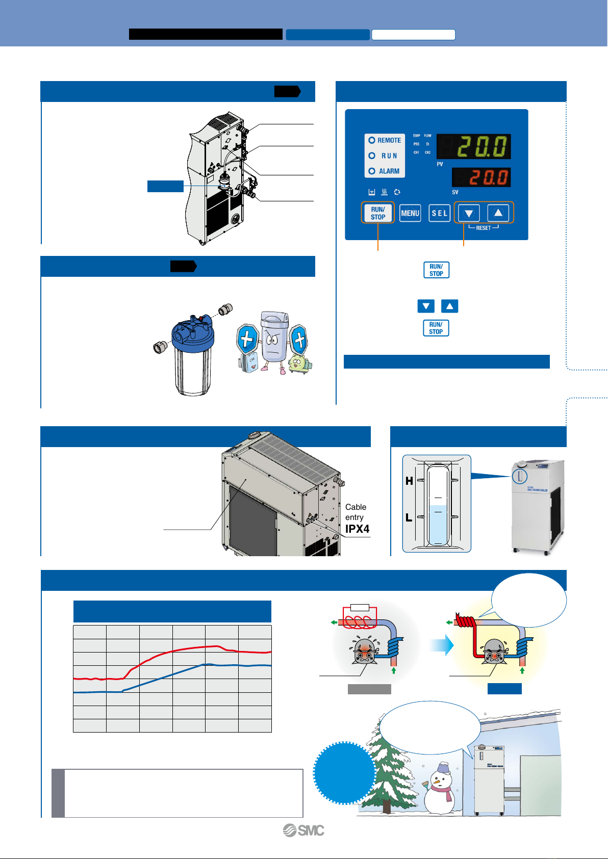
Self-diagnosis function and check display
Display of individual alarm codes
Operation is monitored at all times by the integrated sensor.
Should any error occur, the self-diagnosis result is
displayed by the applicable alarm code.
This makes it easier to identify the cause of the alarm.
Can be used before requesting service
Check display
The internal temperature, pressure, and
operating time of the product are displayed.
Changeable alarm set values
Setting item
Circulating fluid discharge pressure rise
Circulating fluid discharge pressure drop
Set range
0.3 to 0.6 MPa
0.05 to 0.6 MPa
Displayed item
Circulating fluid outlet temperature
Circulating fluid return temperature
Compressor gas temperature
Circulating fluid outlet pressure
Compressor gas discharge pressure
Compressor gas return pressure
Accumulated operating time
of the thermo-chiller
Accumulated operating time
of the pump
Accumulated operating time
of the fan∗
1
Accumulated operating time
of the compressor
Accumulated operation time
of the dustproof filter∗
1
Ex. RUN “Accumulated operating
time of the thermo-chiller”
Ex.
AL01 “Low level in tank”
∗1 These are displayed only
for air-cooled refrigeration.
For details, refer to page 17.
Convenient functions (Refer to the Operation Manual for details.)
Anti-freezing operation function
If the circulating fluid approaches its freezing point, for example, on a cold
winter night, the pump operates automatically, and the heat generated by
the pump warms the circulating fluid, preventing freezing.
Key-lock function
Can be set in advance to protect the set values from being
changed by pressing keys by mistake
Function to output a signal for completion of preparation
Notifies by communication when the temperature reaches the pre-set
temperature range
PC
HRLE Remote
operation
switch Output 1
Output 2
Output 3
Input 2Input 1 Customer
equipment
HRLE
HRLE
Remote signal I/O through
serial communication
Remote operation is enabled (to start and
stop operation) through serial
communication.
Alarm and operation
status (start, stop, etc.)
signal output
The alarm and status generated in the
product can be output.
Remote operation signal input
One of the contact inputs is used for remote
operation and the other is used to monitor the
flow of a flow switch. This is where their alarm
outputs are taken in.
Flow switch
Low flow switch
flow signal
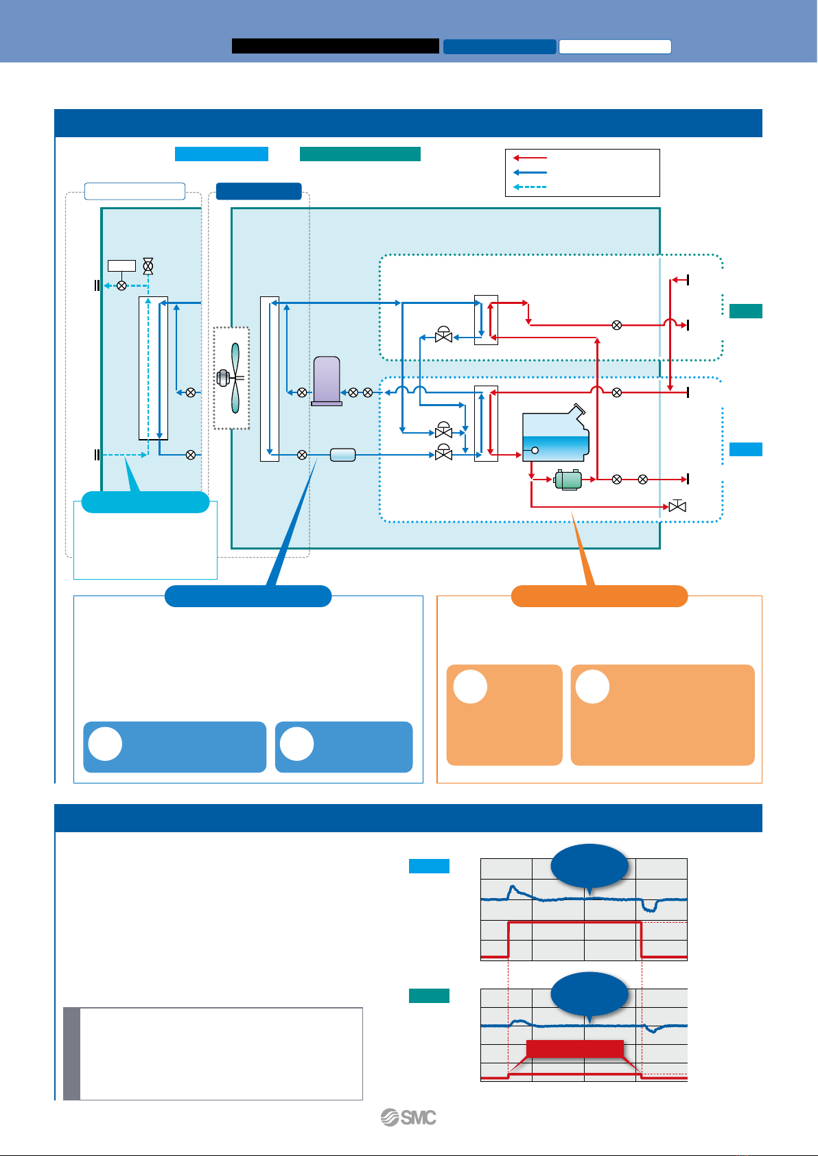
Output examples
Output 1: Operation status (start, stop, etc.)
Output 2: Alarm status signal
Output 3: Preparation completion status signal
Ex.1 Ex.2 Ex.3
¡
Circulating fluid temperature setting
¡Start and stop
¡Circulating fluid
discharge
temperature
¡
Circulating fluid discharge pressure
¡Run and stop status
¡Alarm information
¡Various setting information
¡Preparation completion status, etc.
Power for flow switches (24 VDC) can be
supplied by the thermo-chiller.
Serial communication (RS485) and contact I/Os (2 inputs and 3 outputs)
are equipped as standard.
This allows for communication with the customer equipment and system
construction, depending on the application.
A 24 VDC output can be also provided and is available for use with flow
switches (SMC’s PF3W, etc.).
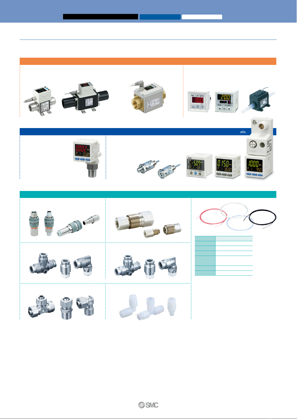
Communication functions p. 18
Communication cable
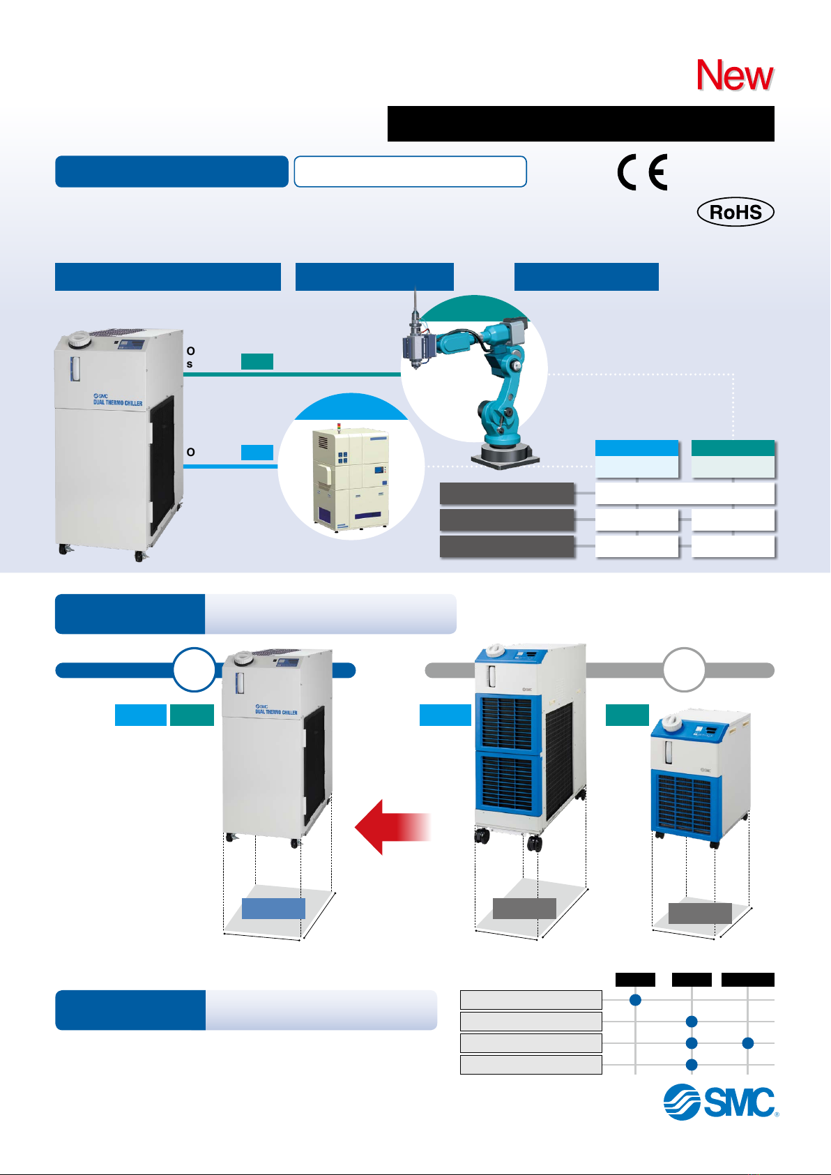
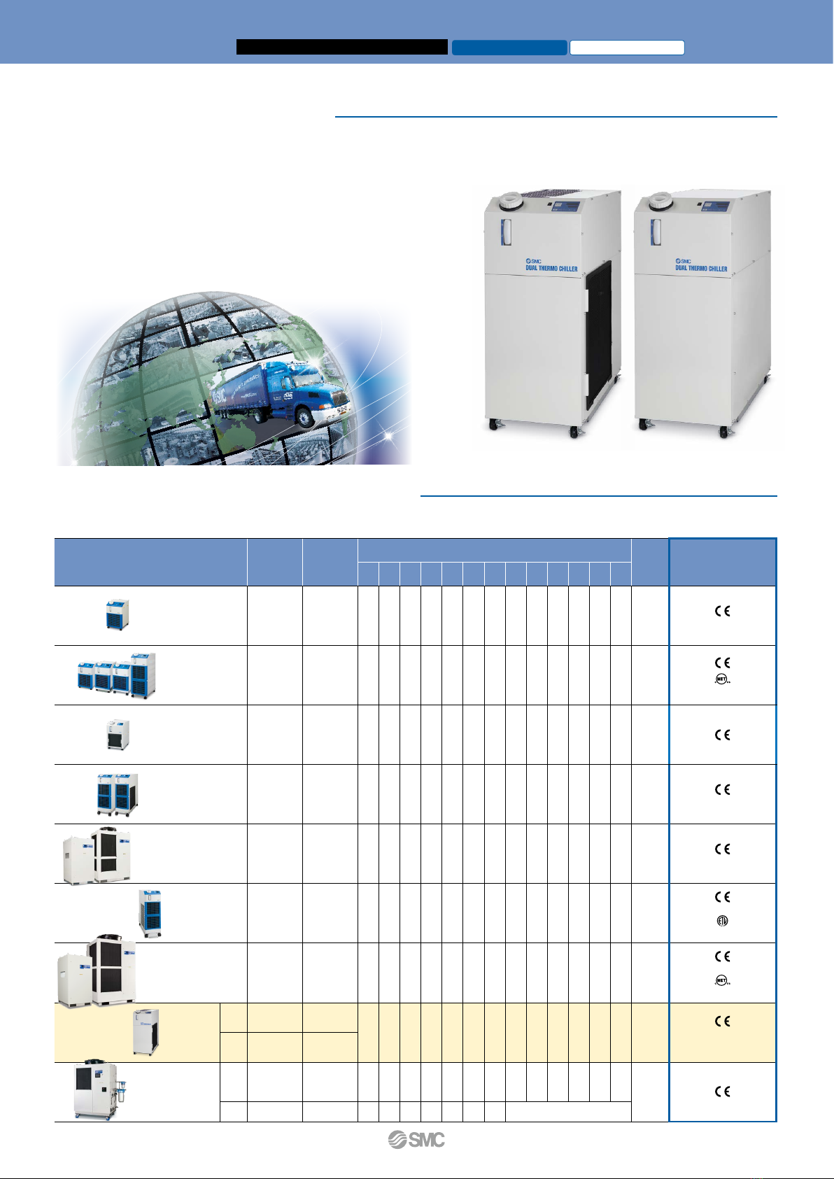
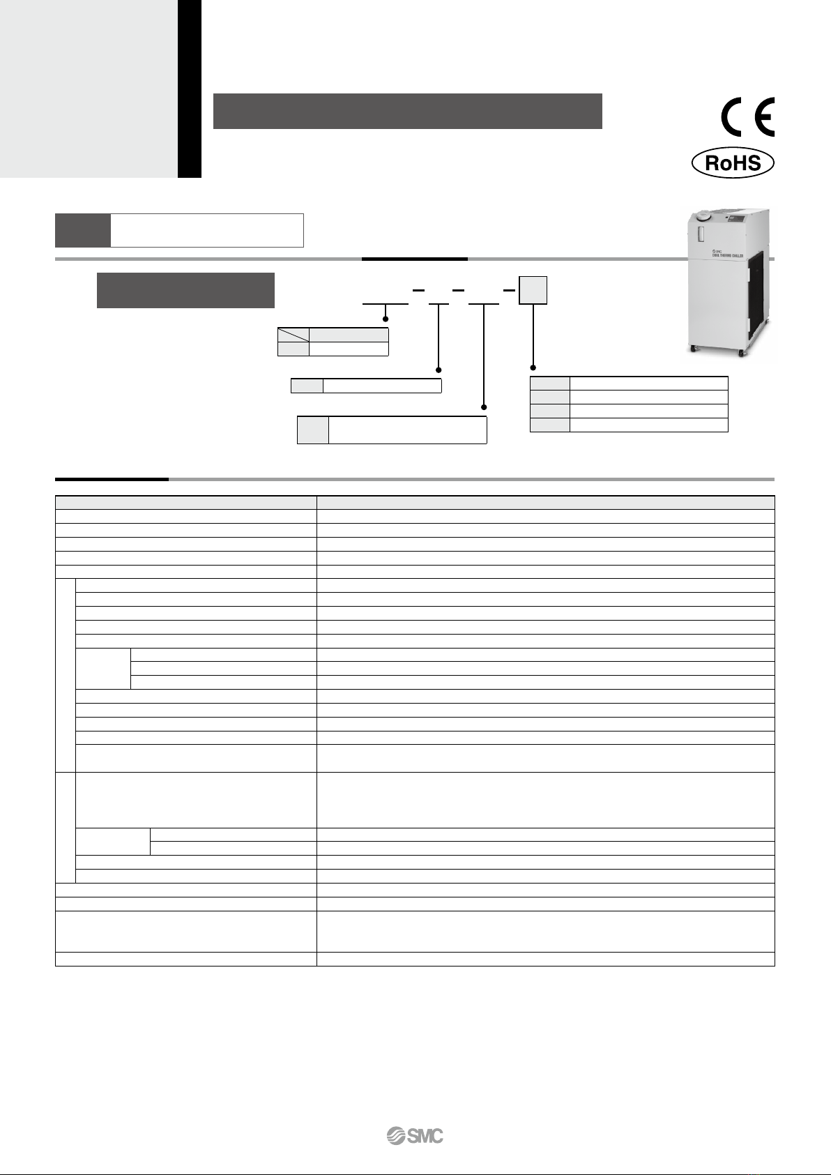
Circulating Fluid Temperature Controller
Thermo-chiller Compact Dual/Basic Type for Lasers
Air-cooled Refrigeration
Water-cooled Refrigeration
HRLE Series