OWNER’S MANUAL 2007
ENGLISH
13
12
DEUTSCH
FRANÇAIS
1. sit on the bike, put your feet on the pedal [9]
2. ask a second person, to put the color beam of
the SAG-Boy, recommended for your bike model,
aside the eye-to-eye distance of the shock bolts.
- if the distance between the bolts is corresponding
to the length of the color beam, the air pressure is
matching to your weight
-if the distance between the bolts is shorter than
the length of the color beam, the air pressure of
the positive chamber is too high and should be
carefully reduced by using the bleed knob of the
shock pump until the measures are corresponding
[10]
-If the distance between the bolts is longer than
the length of the color beam, the air pressure of
the positive chamber is too low and should be
increased by using the shock pump until the mea-
sures are corresponding.
We recommend to make sure that the pressure balance
between positive and negative chamber follows the
recommendations shown on the shock housing.
Not doing so may cause a loss in performance or com-
fort or may result in damage of the shock.
After adjusting positive and negative chamber accor-
ding to the rider’s weight you can double check by
using the SAG-Boy, which is on the back of the manual,
if the SAG (negative travel) is well adjusted.
The negative travel is important when crossing grooves
or holes on the trail.
If the bike is well adjusted the rear wheel and the swing-
arm will roll through the groove without the mainframe
moving.
The SAG should be 15-20% of the travel for race orien-
ted riders and 20-25% of the travel for comfort oriented
riders.
The SAG-Boy indicates the recommended eye-to-eye
distance of the shock bolts of the different Genius
models.
To check the adjustment, please follow as shown below:
109
SET-UP OF NEGATIVE AIR
CHAMBER GENIUS LC-R SHOCK
SET-UP OF POSITIVE AIR
CHAMBER GENIUS LC-R SHOCK
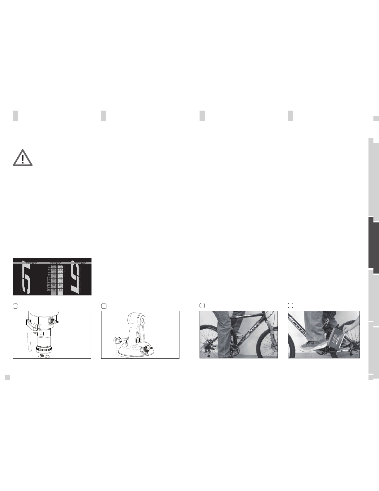
The negative air chamber contains the air-spring
influencing the brake-away and characteristic while
absorbing shocks. A too high brake-away can cause an
non-secure and uncomfortable ride.
[8]
To adjust the air pressure of the negative chamber of
the Scott Genius LC-R Shock please refer to the follo-
wing instruction:
1. Remove the cap of the silver valve (S6) located on
the upper end of the shock housing (S3)
2. Mount the shock pump with its adaptor on the valve
3. Pump the recommended pressure into the shock hou-
sing. On the housing of the shock you will find a table
showing in the silver colored areas the recommended
air pressure of the negative chamber according to the
rider’sweight. Sketch of shock housing decal
4. When you reached the needed pressure remove the
pump and put the valve cap on the valve.
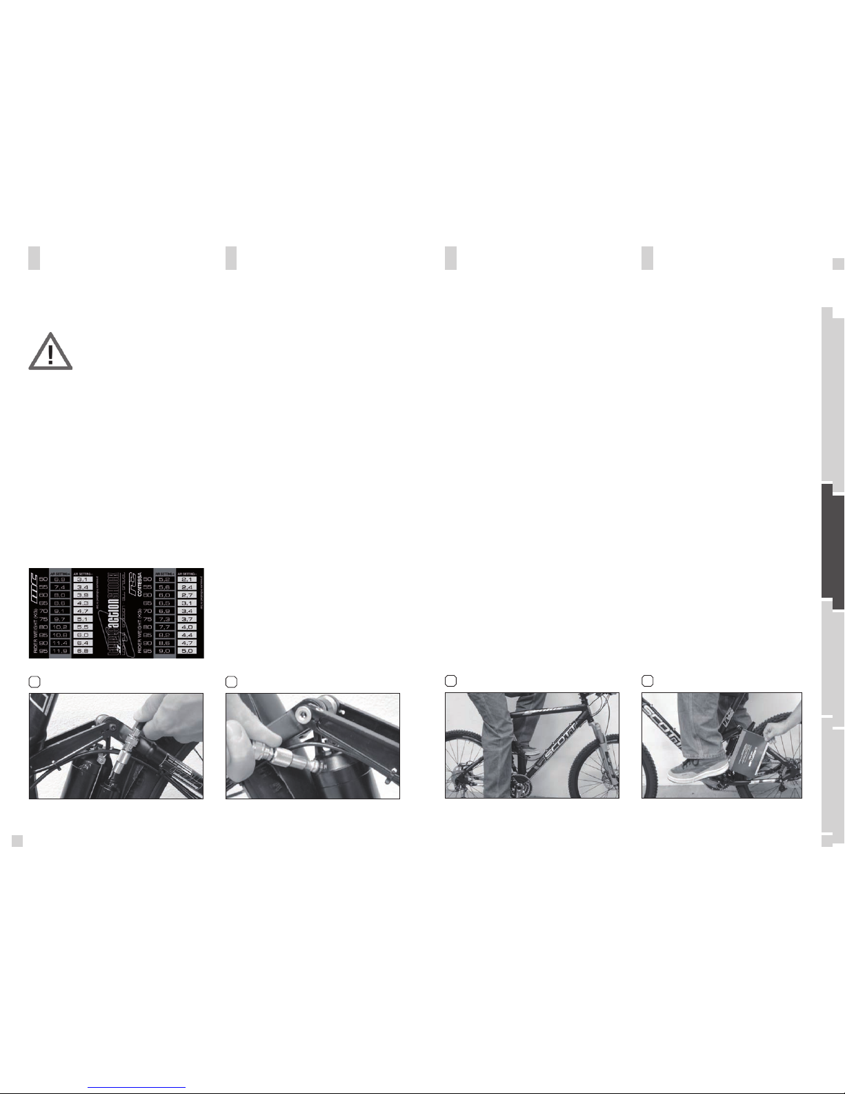
The positive air chamber contains the air-spring you
“sit-on” while riding. [7]
To adjust the air pressure of the positive chamber of
the Scott Genius Shock please refer to the following
instruction:
1. Remove the valve cap of the black valve (S5) located
on the lower end of shock housing (S3)
2. Mount the shock pump with its adaptor on the valve
3. Pump the recommended pressure into the positive
chamber. On the housing of the shock you will find a
table showing in the black colored areas the recom-
mended air pressure of the positive chamber according
to the rider’sweight. Sketch of shock housing decal
4. When you reached the needed pressure remove the
pump and put the valve cap on the valve
7 8
Positive Air Chamber Negative Air Chamber
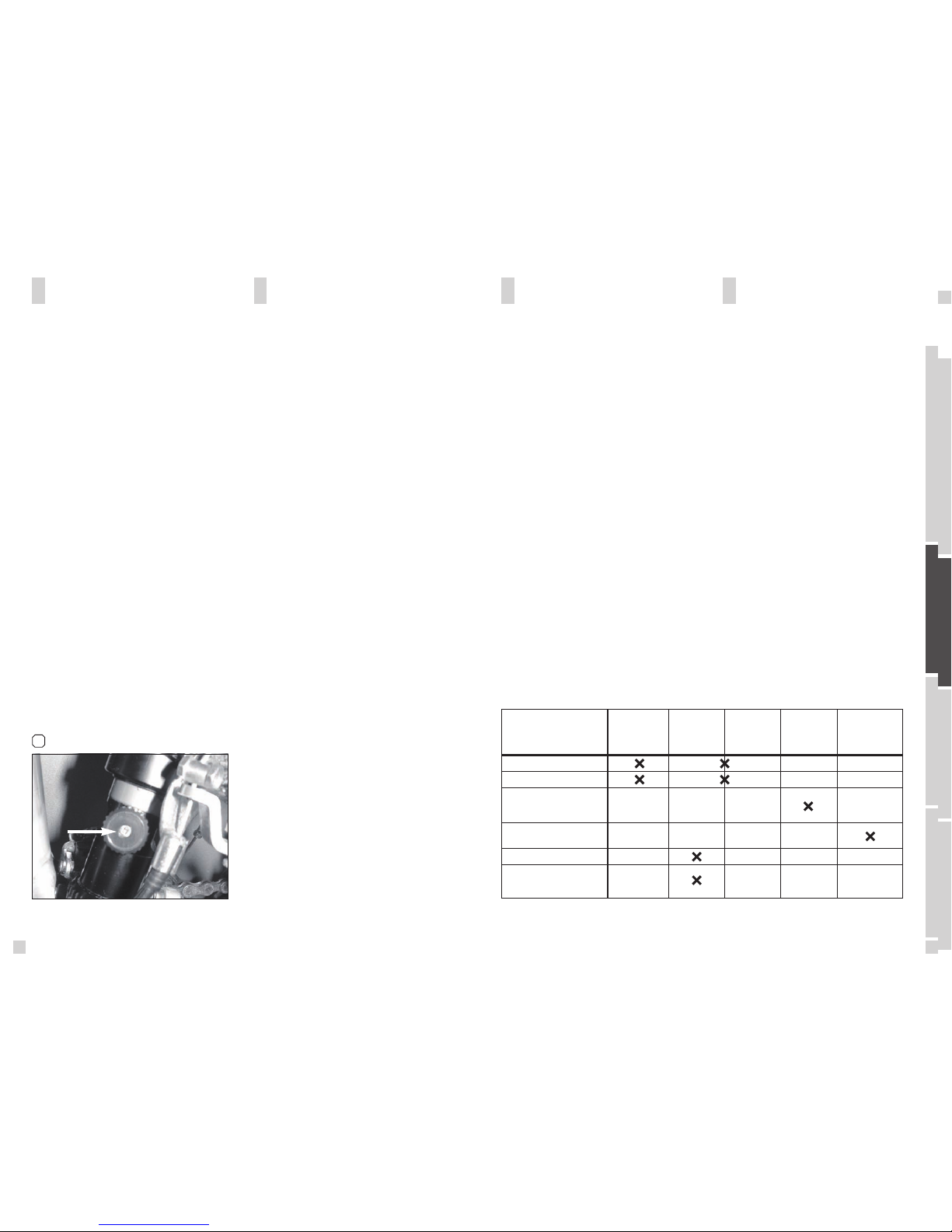
IMPORTANT:
For all adjustments of the air spring
the lock out lever has to be in posi-
tion “all travel”/open
S5
S6