Scott CEN-PAQ User manual

CEN-PAQ
Short Duration Self-contained Breathing Apparatus
User Instructions
Article No. 1034919
Issue H 08. 2005

i
Self-contained Breathing Apparatus
Contents
WARNINGS................................................................................................................................................................. ii
1. INTRODUCTION.............................................................................................................................................1
1.1 IMPORTANT ...............................................................................................................................................1
1.2 BREATHABLE AIR......................................................................................................................................1
1.3 COMPRESSED AIR AIRLINE SUPPLIES...................................................................................................1
1.4 APPARATUS DURATION ...........................................................................................................................2
1.5 PERSONNEL TRAINING ............................................................................................................................2
1.6 SERVICING.................................................................................................................................................2
1.7 SPARE PARTS AND ACCESSORIES ........................................................................................................3
1.8 NOTIFIED BODIES.....................................................................................................................................3
2. TECHNICAL DESCRIPTION ..........................................................................................................................3
2.1 PNEUMATICS.............................................................................................................................................4
2.2 REDUCER...................................................................................................................................................4
2.3 DEMAND VALVE ........................................................................................................................................4
2.4 FACEMASK.................................................................................................................................................5
3. QUALITY ATTRIBUTES .................................................................................................................................5
3.1 NOTIFIED BODIES.....................................................................................................................................5
4. CHECK APPARATUS.....................................................................................................................................6
4.1 FIT FULLY CHARGED CYLINDER.............................................................................................................6
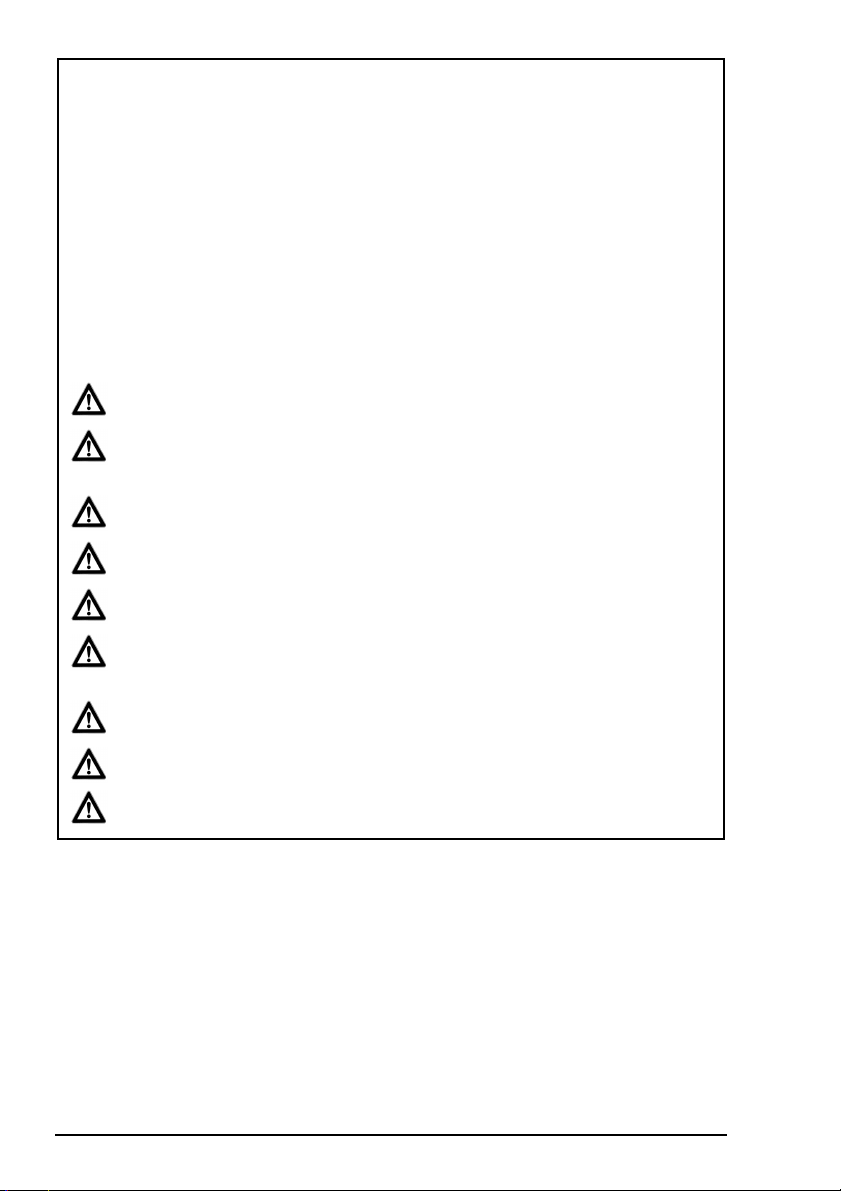
4.2 CHECK DEMAND VALVE...........................................................................................................................6
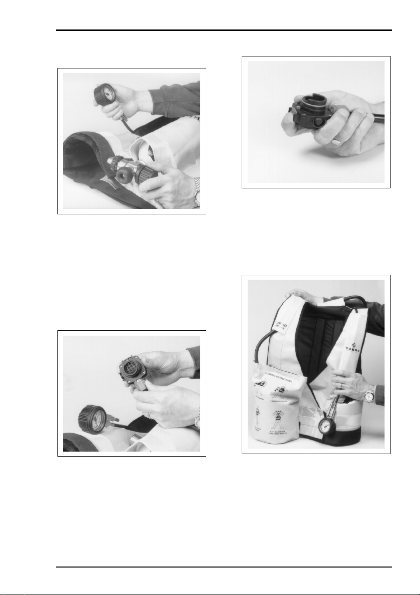
4.3 CHECK CYLINDER PRESSURE / LEAK TEST..........................................................................................7
4.4 WHISTLE TEST..........................................................................................................................................7
4.5 FIT CLEAN FACEMASK .............................................................................................................................7
4.6 CHECK APPARATUS .................................................................................................................................7
5. DONNING & OPERATING PROCEDURE – Standard Apparatus ...............................................................8
5.1 DON APPARATUS......................................................................................................................................8
5.2 CHECK DEMAND VALVE...........................................................................................................................8
5.3 OPEN CYLINDER VALVE...........................................................................................................................9
5.4 DON FACEMASK........................................................................................................................................9
5.5 POSITIVE PRESSURE TEST.....................................................................................................................9
5.6 WHISTLE / FACESEAL TEST ....................................................................................................................9
5.7 CHECK CYLINDER PRESSURE ..............................................................................................................10
6. DONNING & OPERATING PROCEDURE – Airline Apparatus..................................................................10
6.1 DON APPARATUS....................................................................................................................................10
6.2 CHECK DEMAND VALVE.........................................................................................................................11
6.3 CONNECT SUPPLY..................................................................................................................................11
6.4 FIT FACEMASK ........................................................................................................................................11
6.5 POSITIVE PRESSURE TEST...................................................................................................................11
6.6 FACESEAL TEST......................................................................................................................................12
6.7 OPERATING CYLINDER SUPPLY ...........................................................................................................12
7. DOFFING INSTRUCTIONS ..........................................................................................................................13
7.1 REMOVE FACEMASK ..............................................................................................................................13
7.2 TURN OFF CYLINDER VALVE / DISCONNECT SUPPLY.......................................................................13
7.3 REMOVE APPARATUS ............................................................................................................................14
7.4 CLEAN & TEST APPARATUS ..................................................................................................................14
8. AFTER USE ..................................................................................................................................................14
8.1 CLEAN FACEMASK..................................................................................................................................14
8.2 CLEAN APPARATUS................................................................................................................................15
8.3 CHECK APPARATUS ...............................................................................................................................15
8.4 RECORD TEST DETAILS.........................................................................................................................15
8.5 STORAGE.................................................................................................................................................16
9. SCHEDULED MAINTENANCE.....................................................................................................................16
9.1 MONTHLY.................................................................................................................................................16
9.2 ANNUALLY ...............................................................................................................................................16
Registered office: Scott Health and Safety Limited, Pimbo Road, West Pimbo,
Skelmersdale, Lancashire, WN8 9RA, United Kingdom.

ii
WARNINGS
Please Read Carefully and Fully Understand
This manual is for use by personnel trained in the use and care of compressed air
breathing apparatus, and MUST NOT be used as a self-teaching guide by untrained users.
Failure to understand or adhere to the CEN-PAQ user instructions may result in injury or
death.
Scott Health and Safety Limited have taken great care to ensure that the information in
this manual is accurate, complete and clear. However, Training & Technical Support
Services will be pleased to clarify any points in the manual and answer questions on
SCOTT breathing apparatus.
The following warnings are in accordance with certifying authority requirements
and apply to the use of breathing apparatus in general:
Breathing apparatus users must be fully trained in the use and care of self-
contained, compressed air breathing apparatus.
Ensure that the selection of the apparatus type is sufficient for the tasks
being undertaken and the hazards likely to be encountered. Please refer to
National Regulations for guidance.
Adequate protection may not be provided in certain highly toxic
atmospheres.
The apparatus must be tested and serviced in accordance with Section 9 -
Scheduled Maintenance and the notes in Section 1 under Servicing.
The quality of air used to supply and charge breathing apparatus must meet
the requirements of EN 12021 : 1995. See Section 1 for details.
Ensure that a good seal can be obtained between the face and facemask.
The wearing of beards, side-burns or spectacles may adversely affect the
sealing of a facemask to the wearer's face.
At high work rates, facemask pressure may become negative at peak
inhalation.
The apparatus is not designed for use underwater.
The waistcoat/harness must not be used as a vehicle seat restraint.
DISCLAIMER
Failure to comply with these instructions or misuse of the apparatus may result in:
death, injury or material damage, and invalidate any warranty or insurance claims.
COPYRIGHT
This manual must not be copied in part or in whole, or used for purposes other than its
intended purpose without the written permission of Scott Health and Safety Limited.

CEN-PAQ
1
1. INTRODUCTION
1.1 IMPORTANT
CEN-PAQ must be serviced in
accordance with the Servicing Schedule
on at least an annual basis. Please refer
to notes under Servicing.
These instructions for the use, care and
maintenance of the apparatus must be
followed to ensure the correct and safe
operation of CEN-PAQ.
For any enquiries regarding the use of
SCOTT breathing apparatus, please
contact Training & Technical Support
Services at Scott Health and Safety
Limited.
1.2 BREATHABLE AIR
Air used to supply or charge breathing air
may be natural or synthetic. The
composition of breathable air is given in
Table 1.
COMPONENT MASS %
(Dry Air)
VOLUME %
(Dry Air)
OXYGEN 23.14 20.948
NITROGEN 75.52 78.08
ARGON 1.29 0.93
CARBON
DIOXIDE 0.05 0.031 4
HYDROGEN 0.000 003 0.000 05
NEON 0.001 270 0.001 818
HELIUM 0.000 037 0.000 524
KRYPTON 0.000 330 0.000 114
XENON 0.000 039 0.000 009
Table 1: Breathable Air
There is an increased fire risk when the
oxygen content is above the value shown
above.
The purity/quality of air used to supply
and charge breathing apparatus should
be tested periodically in accordance with
national regulations.
Unless specified otherwise, the
contaminants shall not exceed the
permissible exposure level.
National regulations must be observed.
The mineral oil content shall be such that
the air is without the odour of oil. The
odour threshold is in the region of 0.3
mg/m
3
.
The water content shall not exceed 50
mg/m
3
for 200 bar apparatus and 30
mg/m
3
for 300 bar apparatus.
For airline apparatus, air must be used
with a dew-point sufficiently low to
prevent internal freezing.
1.3 COMPRESSED AIR
AIRLINE SUPPLIES
Air for use with compressed air airlines
must conform to prEN 12021 : 1995 and
must have a dew point sufficiently low to
prevent internal freezing when apparatus
is used in temperatures below 4°C.
No. of Wearers Airflow (L/min.)
1
2
3
4
300
450
750
900
Table 2
Airline pressure must be between 5.0 -
9.0 bar (70 - 130psi). Airflow supply
capacity for a single airline is given in
Table 2.
Generally, each additional wearer
requires an extra 150 litres/minute, each
additional pair of wearers requires 300
L/min for one wearer and 450 L/min for
two wearers. All measurements must be
taken at the wearer end of the airline.
Example: for 8 users (4 pairs) the
recommended flow is 4 x (300 + 150) =
1800 litres/minute.
An Airline Flow Tester is available from
Scott Health and Safety Limited under
Article Number 1035978.

CEN-PAQ
2
Compressed air airlines used with
CEN-PAQ must be SCOTT products,
approved to EN 139.
Ensure that hoses used in an explosive
or inflammable atmosphere are marked
ANTI-STATIC – EN 139.
Cost effective PVC hoses may be used in
other atmospheres.
SCOTT manufacture a range of anti-
static and PVC hoses, in lengths ranging
from 15m to 60m. Customer Services
will be pleased to advise on price and
delivery.
1.4 APPARATUS DURATION
All durations quoted are nominal, based
on an Average Wearer Consumption
Rate of 40 litres/minute and FULLY
CHARGED cylinders. Actual Wearer
Consumption rates vary due to many
factors, such as:
1. Workload: high work rates increase
consumption rates.
2. Weight of apparatus and use of
heavy or restrictive clothing.
3. Work environments with extremes
of heat or cold.
4. Physical fitness of the wearer.
5. Other factors include emotional
stress and fatigue.
It is important that all wearers are aware
of these factors and take account of them
when assessing cylinder duration.
The Total Duration for the apparatus is
calculated to be 15 minutes for 200 bar
cylinders and 20 minutes for 300 bar
cylinders based on a free air capacity of
600 or 820 litres and an Average Wearer
Consumption Rate of 40 litres/minute.
The Warning Period is calculated to be 5
minutes based on a 68 bar whistle and a
3 litre cylinder.
The Nominal Duration for the apparatus
is therefore 10 or 15 minutes.
1.5 PERSONNEL TRAINING
Personnel who use self-contained,
compressed air breathing apparatus must
be fully trained in accordance with these
instructions and national regulations.
These instructions cannot replace an
accredited training course run by fully
qualified instructors in the proper and
safe use of SCOTT breathing apparatus.
Please contact Training & Technical
Support Services or your SCOTT
distributor for training course details.
Training & Technical Support
Services:
Scott Health and Safety Limited
Pimbo Road, West Pimbo,
Skelmersdale, Lancashire,
WN8 9RA, United Kingdom.
Tel: +44 (0) 1695 711711
Fax: +44 (0) 1695 711775
1.6 SERVICING
CEN-PAQ must be serviced at scheduled
intervals by personnel who have
completed a formal training course and
hold a current certificate for servicing and
repairing SCOTT breathing apparatus.
Details of the servicing schedule are
contained in the SCOTT CEN-PAQ
Service Manual, copies of which can only
be obtained by registered holders of a
current certificate.
Your SCOTT distributor or Training &
Technical Support Services will be
pleased to provide training course details
and quotes for service contracts. Please
see above for contact details.

CEN-PAQ
3
1.7 SPARE PARTS AND
ACCESSORIES
Our Customer Services Department
provide an efficient friendly, customer
contact point for ordering new apparatus,
spare parts and accessories. The team
can also provide general information on
SCOTT products.
Customer Services:
Scott Health and Safety Limited
Pimbo Road, West Pimbo,
Skelmersdale, Lancashire,
WN8 9RA, United Kingdom.
Tel: +44 (0) 1695 711711
Fax: +44 (0) 1695 711775
1.8 NOTIFIED BODIES
Inspec International Ltd (No. 0194)
Upper Wingbury Courtyard,
Wingrave, Aylesbury,
Buckinghamshire,
HP22 4LW,
United Kingdom.
British Standards Institute (No. 0086)
389 Chiswick High Road,
London,
W4 4AL,
United Kingdom.
2. TECHNICAL
DESCRIPTION
The CEN-PAQ is a waistcoat-mounted,
short duration, self-contained breathing
apparatus.
The apparatus is available in two
versions, a standard SCBA version and
an airline version.
The airline version is fitted with a
waistbelt-mounted manifold allowing the
apparatus to be supplied from a
breathable compressed airline supply.
The apparatus is certified to European
Standard EN 137 for self-contained
breathing apparatus and EN 139 for
airline apparatus and has been issued
with a 'CE' mark.
The apparatus comprises a waistcoat, a
high-pressure air cylinder, two stage
pneumatic system with pressure reducer
and demand valve; and a facemask.
The facemask-mounted, high
performance demand valve ensures that
positive pressure is maintained within the
facepiece, thus providing the highest
degree of respiratory protection.
For airline apparatus, a medium
pressure, compressed airline supply is
connected to a waistbelt-mounted
manifold, thus supplying air directly into
the medium pressure port on the
pressure reducer.
A 3-litre water capacity, 200 or 300 bar
cylinder which provides a free air capacity
of 600 or 820 litres is mounted in a pouch
on the back of the jacket. This allows a
total duration of 15 or 20 minutes when
used at an average wearer consumption
rate of 40 litres/minute, (please refer to
Section 1.4 - Apparatus Duration for
further details).
The apparatus utilises a waistcoat
fabricated from either a high visibility
P.V.C. or a black, anti-static material.
The standard apparatus features a
double-breasted Velcro
TM
fastening
waistcoat whereas anti-static and airline
versions feature a double buckle closure.

CEN-PAQ
4
The high visibility waistcoat MUST NOT
be used in potentially explosive or
flammable atmospheres.
The waistcoat is designed to fit a wide
range of body sizes with the minimum of
adjustment.
The alloy steel cylinder has a brass
cylinder valve with a handwheel. A safety
lock on the handwheel prevents
accidental valve closure. The cylinder is
retained in the pouch by a tough, dual
action buckle.
2.1 PNEUMATICS
High-pressure air from the cylinder is
connected through the cylinder valve and
a length of high-pressure hose to a
pressure reducer. A sintered filter in the
connector prevents the ingress of dirt and
debris.
A high-pressure hose from the reducer
supplies air to the shoulder-mounted
pressure gauge and warning whistle
assembly. The gauge dial has photo-
luminescent markings to improve low-
light legibility. The gauge is protected by
means of a rubber shroud.
The warning whistle operates at 68 bar,
when there is at least 200 litres of air left
in the cylinder, giving a warning period of
5 minutes when consumed at 40
litres/minute (please refer to Section 1.4 -
Apparatus Duration for further details).
The high-pressure hose has a minimum
burst pressure of 800 bar.
2.2 REDUCER
The pressure reducer operates on a self-
regulating, spring-loaded piston principle
that is completely automatic in operation
and requires no adjustment.
A restrictor within the reducer body
prevents air loss in excess of 25 litres per
minute should the gauge, whistle or hose
become damaged.
A pressure relief valve prevents over-
pressurisation of the medium pressure
breathing circuit.
An outlet pressure of between 5.0 and
11.0 bar from the reducer is supplied to
the facemask-mounted demand valve.
2.3 DEMAND VALVE
Air from the reducer is connected through
a reinforced chlorinated polyethylene
hose to the facemask-mounted DV,
which regulates the air supplied to the
wearer.
The DV operates in conjunction with the
facemask spring-loaded exhale valve to
maintain a positive pressure within the
facemask.
The DV has a servo-assisted tilting
diaphragm mechanism that responds to
pressure changes within the facemask to
regulate the flow of air to the mask,
ensuring that pressure within the mask
remains safely above ambient.
The DV has a reset button that enables
wearers to close the airflow through the
DV, permitting the facemask to be
removed during test procedures and at
the end of a task, without loss of cylinder
air.

CEN-PAQ
5
When the apparatus is donned, the DV is
normally “reset” (closed) and is opened
(activated) when the wearer takes a first
breath.
The DV has a supplementary flow device
(bypass), that the wearer can open using
the bypass knob.
When the bypass is used the unregulated
flow of air through the DV reduces
cylinder duration.
The DV is connected to the facemask by
a Quick-Fit (QF) bayonet fitting with a
spring-loaded locking catch to prevent
accidental disconnection.
2.4 FACEMASK
CEN-PAQ is approved for use with the
PanaSeal facemask. The PanaSeal
facemask is made from non-dermatitic
materials and is available in either black
neoprene or blue silicone and is retained
using a fully adjustable five-point head
harness.
The mask is approved to EN 136 for use
with positive pressure breathing
apparatus.
A speech diaphragm aids
communication.
The mask incorporates an inner mask
that reduces carbon dioxide 'dead space'
and prevents visor misting.
The polycarbonate visor meets the
requirements of EN 136, Part 10, for
impact resistance and optical clarity.
A version of the PanaSeal facemask is
also available for use with the Gallet
TM
helmet.
For airline equipment, the maximum
allowable length of supply hose is 90
metres.
3. QUALITY
ATTRIBUTES
CEN-PAQ is approved to European
Standards EN 137 (Self-contained
breathing apparatus) and is ‘CE’ marked
in accordance with EEC Directive
EC/686/1986.
3.1 NOTIFIED BODIES
Inspec International Ltd (No. 0194)
Upper Wingbury Courtyard,
Wingrave, Aylesbury,
Buckinghamshire,
HP22 4LW,
United Kingdom.
British Standards Institute (No. 0086)
389 Chiswick High Road,
London,
W4 4AL,
United Kingdom.

CEN-PAQ
6
4. CHECK APPARATUS
1. Check apparatus to ensure that it is
clean and in good condition.
2. Fully slacken waistbelts, remove
facemask from pouch and slacken head
harness, ready for use.
4.1 FIT FULLY CHARGED
CYLINDER
1. Slide fully charged cylinder into
pouch and secure using buckle
positioned behind cylinder valve i.e.
towards the wearer.
WARNING:
DO NOT use cylinders of different
sizes or specifications.
2. Check O-ring on cylinder connector
to ensure that it is clean and in good
condition.
3. Screw handwheel connector fully
into cylinder valve outlet.
4.2 CHECK DEMAND VALVE
1. Check red bypass knob is in the
'OFF' position and depress black rubber
reset button.

CEN-PAQ
7
4.3 CHECK CYLINDER
PRESSURE / LEAK TEST
1. Slowly open cylinder valve fully,
check pressure gauge to ensure that the
cylinder is at least 80% FULL:
For 200 bar cylinders - 160 bar.
For 300 bar cylinders - 240 bar.
2. Close cylinder valve and time for
one minute, observing pressure gauge.
The reading must not fall by more than
10 bar in this time.
4.4 WHISTLE TEST
1. Open bypass knob slightly to vent
air from system. Check that the whistle
sounds clearly at between 63 and 73 bar.
When all air has been released, close
bypass.
4.5 FIT CLEAN FACEMASK
1. Check that orange O-ring on
demand valve outlet is clean and in good
condition.
2. Fit demand valve to facemask,
checking that coupling is secure by
rotating valve back and forth.
4.6 CHECK APPARATUS
1. Slacken all straps and check
apparatus to ensure that it is clean and in
good condition.
2. Stow facemask in pouch.
3. Apparatus is now ready for use.
4. If apparatus fails test DO NOT
USE. Attach explanatory note to
apparatus and return for servicing.

CEN-PAQ
8
5. DONNING &
OPERATING
PROCEDURE –
Standard Apparatus
5.1 DON APPARATUS
1. For Velcro
TM
fastened waistcoats:
Fit left side of jacket to inside and pass
right side around outside and secure for a
snug fit.
2. For black waistcoats: Pass right
side of jacket to inside and secure
buckle. Pull strap to adjust for
comfortable fit.
3. Pass left side of jacket around
outside and secure buckle, pull strap and
adjust for a comfortable fit. Tuck loose
ends of straps inside waistcoat.
5.2 CHECK DEMAND VALVE
1. Remove facemask from stowage
pouch and hang from strap around neck.
2. Check demand valve to ensure that
the red bypass knob is in the 'OFF'
position and depress black reset button.

CEN-PAQ
9
5.3 OPEN CYLINDER VALVE
1. Open cylinder valve fully. Check
pressure gauge to ensure that the
cylinder is at least 80% FULL:
For 200 bar cylinders - 160 bar.
For 300 bar cylinders - 240 bar.
5.4 DON FACEMASK
1. With head harness straps fully
slackened, place chin into chin-cup and
pull harness straps over back of head.
2. Tighten head harness straps in
sequence: bottom, middle, top. DO
NOT over-tighten.
3. Inhale sharply to actuate first
breath mechanism. Breathe normally.
5.5 POSITIVE PRESSURE
TEST
1. Insert finger under face-seal and
check for a steady outward flow of air.
2. Remove finger and allow facemask
to re-seal.
5.6 WHISTLE / FACESEAL
TEST
1. Release the handwheel lock and
close the cylinder valve. Keep hold of the
handwheel.
2. Hold breath and listen carefully for
any leaks. Check pressure gauge as
movement of the needle indicates a leak.
3. If test fails, open cylinder valve,
slacken head harness, adjust mask and
repeat test as required.

CEN-PAQ
10
4. Slowly breathe down air in system.
Check pressure gauge to ensure that
whistle sounds clearly at 55 bar ±5 bar.
5. Open cylinder valve fully upon
completion.
6. If leak persists, DO NOT use.
Attach explanatory note and return for
servicing.
5.7 CHECK CYLINDER
PRESSURE
1. Turn the red bypass to ON and
check that there is a steady flow of air
into the mask. Turn the bypass to OFF.
2. Check pressure gauge to ensure
that the cylinder is at least 80% FULL:
For 200 bar cylinders - 160 bar.
For 300 bar cylinders - 240 bar.
3. Ensure that there is sufficient air in
the cylinder for the tasks to be performed.
4. The apparatus is ready for use.
6. DONNING &
OPERATING
PROCEDURE –
Airline Apparatus
6.1 DON APPARATUS
1. Pass right side of jacket to inside
and secure buckle.
2. Adjust strap for comfortable fit.
3. Pass left side of jacket around
outside and secure buckle, pull strap and
adjust for a comfortable fit.

CEN-PAQ
11
4. Tuck loose ends of straps inside
waistcoat.
WARNING:
Ensure that the cylinder valve is
turned OFF.
6.2 CHECK DEMAND VALVE
1. Remove facemask from stowage
pouch and hang mask from strap around
neck.
2. Check demand valve to ensure that
the red bypass knob is in the 'OFF'
position and depress black reset button.
6.3 CONNECT SUPPLY
1. Connect airline supply hose to plug
connector on waistbelt. Firmly pull on
connector to ensure that coupling is
secure.
WARNING:
Airline supply pressure and flow must
be checked to ensure it meets the
requirements of Section 1.3.
6.4 FIT FACEMASK
1. With head harness straps fully
slackened, place chin into chin-cup and
pull harness straps over back of head.
2. Tighten head harness straps in
sequence: bottom, middle, top. DO
NOT over-tighten.
3. Inhale sharply to actuate first
breath mechanism. Breathe normally.
6.5 POSITIVE PRESSURE
TEST
1. Insert finger under faceseal and
check for a steady outward flow of air.
Remove finger and allow mask to re-seal.

CEN-PAQ
12
6.6 FACESEAL TEST
1. Push hose couplings together and
pull back collar to release supply hose.
2. Breathe normally until mask is
pulled gently onto face and hold breath
for 10 seconds. Any leakage will be
indicated by the mask moving away from
the face.
3. Re-connect coupling and breathe
normally upon completion.
4. Hold breath and listen for any
audible leaks.
5. If test fails, slacken then adjust
head-harness and repeat test as
required.
6. If leak persists, DO NOT USE.
Attach explanatory note to apparatus and
return for servicing.
7. Open bypass on demand valve to
check for steady inward flow of air, close
on completion.
8. Once satisfied with apparatus,
proceed to undertake tasks as required.
6.7 OPERATING CYLINDER
SUPPLY
1. DO NOT operate cylinder supply
whilst connected to airline supply unless
in the process of egress or escape.
WARNING:
Operating the bypass facility whilst
using the cylinder supply will
significantly reduce the duration of the
apparatus.
2. Open cylinder valve fully.
3. Push hose couplings together and
pull back collar to release supply hose.
4. Breathe normally and continue as
required.

CEN-PAQ
13
7. DOFFING
INSTRUCTIONS
7.1 REMOVE FACEMASK
WARNING:
DO NOT remove apparatus until clear
of the hazard area.
1. Take a deep breath and depress
black reset button on demand valve.
2. Release head harness by pulling
metal buckles forward.
3. Hang mask from strap around
neck.
7.2 TURN OFF CYLINDER
VALVE / DISCONNECT
SUPPLY
1. Disengage handwheel locking
mechanism and close cylinder valve.
2. Push hose couplings together and
pull back collar to release supply hose.
3. Turn red bypass knob to 'ON'
position and bleed air from system.

CEN-PAQ
14
7.3 REMOVE APPARATUS
1. Stow mask in pouch and secure to
waistcoat.
2. Release waistbelt to remove
apparatus.
3. Unscrew handwheel connector and
release buckle to remove cylinder.
4. Mark cylinder as empty (if used)
and return for charging.
7.4 CLEAN & TEST
APPARATUS
The apparatus must be cleaned and
tested in accordance with the instructions
given in Section 8 - After Use, prior to
being returned into service.
8. AFTER USE
Cautions:
•DO NOT immerse the demand
valve or warning whistle in
water. A yellow cap is provided
to cover the demand valve
outlet.
•USE ONLY the specified method
and substances to clean the
apparatus.
•The apparatus MUST be
thoroughly dried prior to
storage, in particular the
facemask and valve flaps.
8.1 CLEAN FACEMASK
1. Withdraw red locking catch and
turn demand valve 90° clockwise to
disconnect demand valve from facemask.
2. Wash mask thoroughly in a hand
hot solution of TriGene
TM
Cleansing and
Disinfecting Solution. See Note below.
3. Rinse mask thoroughly in clean
running water, paying particular attention
to flushing out the exhale valve.
4. Hang mask by neckstrap and allow
to dry thoroughly away from direct heat or
sunlight.
5. When dry, wipe facemask seals
with TriGene
TM
disinfectant wipes.
6. Polish visor inside and out with a
clean, lint-free cloth. Fit ‘Visorguard’ to
protect visor if desired.
7. Slacken head harness, ready for
use.
Note:
TriGene
TM
Cleansing and Disinfecting
Solution is available from Scott Health
and Safety Limited in 1 litre and 5 litre
containers under Article Numbers
2008247 and 2008248 respectively.
Pump dispensers are available for the
above under Article Numbers 1017672 (1
litre) and 1017670 (5 litres).
TriGene
TM
Disinfecting Wipes are
available from Scott Health and Safety
Limited in packs of 20 sachets under
Article Number 2004225.

CEN-PAQ
15
8.2 CLEAN APPARATUS
1. Fully slacken waistbelt straps.
2. Clean off any dirt by sponging
down with a warm water and soap
solution followed by a thorough rinse.
8.3 CHECK APPARATUS
1. Check that the demand valve
locking catch is free to move without
sticking by depressing the catch a
number of times.
2. To clean catch, cover valve outlet
with yellow cap and use a small brush
and soap solution to clean around catch.
3. If catch is not free moving, attach
explanatory note to apparatus and return
for servicing.
Notes:
•Due to the configuration of the
apparatus, it is not necessary to
decontaminate the internal
components of the demand valve.
•DO NOT immerse or attempt to
clean the internals of the demand
valve.
4. Examine waistcoat to ensure that it
is clean and undamaged. In particular
examine for signs of abrasion or fraying.
Note: It is possible to wash the waistcoat
separately, provided the pneumatic
assembly is removed. Please refer to the
CEN-PAQ Service Manual for details.
5. Carefully examine apparatus for
signs of wear or damage, ensuring that
any faults are rectified immediately in
accordance with the servicing
instructions.
6. Functionally check the apparatus in
accordance with instructions provided
within Section 4 of this manual.
8.4 RECORD TEST DETAILS
Record test details in accordance with
local regulations in a breathing apparatus
logbook (available from Scott Health and
Safety Limited under Article Number
1034745).
Information recorded usually includes:
•Name and address of employer
responsible for the apparatus.
•Make, model number or mark of
the apparatus, together with a
description of any distinguishing
features, sufficient to enable clear
identification.
•The date of the examination
together with the name, signature
or unique authentication mark of
the examiner.
•The condition of the apparatus and
details of any defects found and
any remedial action taken,
including any airline supply
equipment used with the
apparatus.
•Cylinder air pressure.

CEN-PAQ
16
8.5 STORAGE
The apparatus must be stored in a clean
dry environment away from direct heat
and sunlight.
Storage temperature should not exceed
+40°C to -10°C.
9. SCHEDULED
MAINTENANCE
9.1 MONTHLY
The apparatus should be examined and
tested at least once a month in
accordance with the instructions given in
this manual under Check Apparatus.
Details of such checks should be
recorded within the appropriate register
and a copy kept for future inspection.
Please see Section 8.4 for details.
9.2 ANNUALLY
The apparatus must be tested and
components replaced in accordance with
the CEN-PAQ Service Schedule,
contained within the CEN-PAQ Service
Manual. Please refer to notes under
Personnel Training and Servicing at the
beginning of this manual for further
details.

Scott Health and Safety Limited
Pimbo Road, West Pimbo,
Skelmersdale, Lancashire,
WN8 9RA, United Kingdom.
Tel: +44 (0) 1695 711711
Fax: +44 (0) 1695 711775
Table of contents
Other Scott Respiratory Product manuals

Scott
Scott SKA-PAK AT Installation and operation manual

Scott
Scott Sigma 2 User manual

Scott
Scott RIT-PAK III Manual

Scott
Scott AV-3000 Service manual

Scott
Scott Profile2 User manual

Scott
Scott M98 Small User manual

Scott
Scott M95 User manual

Scott
Scott Promask User manual

Scott
Scott 2 Troubleshooting guide