Scott Promask User manual

Instructions for Use
ENGLISH
009751-J 01/2010
Promask
Promask2

2
Promask
(thread connection EN 148-1)
Promask2
(bayonet connection)
1
2
3
6b
7b
4
5
6a
7a
7c
8
9
10
(◄)
aligning mark
11

3
Spare parts
1
013355
Inner mask TPE with fastening ring
1
012691
Inner mask SIL with fastening ring
1
013391
Inner mask SIL black with fastening ring
2
2
012692
013312
Head harness PM
Head harness SIL yellow PM
- -
013354
Head harness PM Polynet
3
012694
Buckle set for harness PM (5 pcs)
4
012693
Visor frame set PM
5
012695
012795
Visor PM PC (polycarbonate)
Visor PM HC (hard coated)
6a
6b
012689
Valve seat set PM, including
-1 x Inhalation valve seat
-2 x Inner mask valve seat
7a
7b
7c
012690
Disc set PM, including
-1 x Inhalation valve disc
-2 x Inner mask valve disc
-1 x Exhalation valve disc
8
012687
Speech diaphragm
9
012688
Exhalation valve cover PM
10
012794
Speech channel cover PM
11
----
Faceseal
Accessories
012698
Visorguard PM (10 pcs)
012790
Spectacle frame PM
012699
Screwdriver PM (for Torx20)
141080
Leak-tightness test device Pro-Tester
010185
Carrying case of hard plastic
012595
Carrying bag of textile

4
4.1 4.2 4.3 4.4 4.5
4.6
4.7
Promask Promask2
5.2
Fig A
Fig B

5
Fig C
5.3
Fig D Fig E Fig F
5.4
Fig G
Fig H Fig J
Inner mask disc
Fig X

6
5.5
Fig K Fig L Fig M
5.6
Fig N Fig O Fig P Fig Q
5.7
Fig R Fig S Fig T
Speech channel cover
Fig U Fig V

7
Approved combinations
Promask + filter Pro2000
Gas filter
Combined filter
Particle filter
GF22
GF32
CF22
CF32
CFR22
CFR32
NBC22
PF 10 P R
PFR 10 P R
Promask + Autoflow/Proflow + filter Pro2000
Combined filter
Particle filter
Proflow2 120
Proflow2 SC 120
Proflow2 Ex 120
Proflow3 120
CF22 A P R
CF22 B P R
CF22 AB P R
CF22 ABE P R
CF32 ABEK P R
CF32 ABEKHg P R
PF 10 P R
Proflow2 SC 160
Proflow2 SC asb 160
PF 10 P R
Autoflow 65/120
Autoflow 120
CF22 A P R
PF 10 P R
Promask2+ filter Pro2
Gas filter
Combined filter
Particle filter
A1
A2
A1B1E1
A1B1E1K1
A1-P3 R
A2-P3 R
A1B1E1-P3 R
A1B1E1K1-P3 R
P3 P R
WARRANTY
The products manufactured at our factories in Skelmersdale and Vaasa carry a warranty of 12
months (unless stated otherwise) for parts, labour and return to site. The warranty period runs from
the date of purchase by the end user.
These products are warranted to be free from defects in materials and workmanship at the time of
delivery. Scott will be under no liability for any defect arising from wilful damage, negligence,
abnormal working conditions, failure to follow the original manufacturers instructions, misuse or
unauthorised alteration or repair.
Evidence of purchase date will need to be provided for any claims arising during the warranty period.
All warranty claims must be directed through Scott Customer Services and in accordance with our
sales return procedure.

8
Year of manufacture: in the facepiece (on the upper middle strap of the mask).
year
week
2003, week 9
in the head harness (rubber)
year
quarter-of-year
2001, January-March
Symbolit
-10 ºC
+50 ºC
< 75 %
See Instructions for Use!
Recommended storage conditions (temperature and humidity).
Promask2:
Twin-filter-use (2 filters / same type + class).
BGIA, DE-53754 Sankt Augustin, Australia Russia
Germany
01

9
Spark guard replaces exhalation valve cover.
Spark guard covers speech channel.
Recommended to use in dirty
circumstances and in welding.
1
2

10
Full face mask ENGLISH
Promask
+ filter Pro2000
+ blower device Autoflow, Proflow
012681 Promask black
012670 Promask S (small) black
012882 Promask SIL yellow
Promask2
+ 2 x filter Pro2
012890 Promask2SIL grey
The Promask has been designed to conform with EN 136/12942 (Europe) and AS/NZS 1716:2003
(Australia/NZ). EC certified by BGIA (Berufsgenossenschaftliches Institut für Arbeitssicherheit), DE-53754
Sankt Augustin, Germany, ID: 0121. Licence 0858 by SAI Global, Australia.
1. General
The Promask is designed to protect the respiratory system and face against hazardous gases and
particles.
The filter is selected according to the type of hazard present.
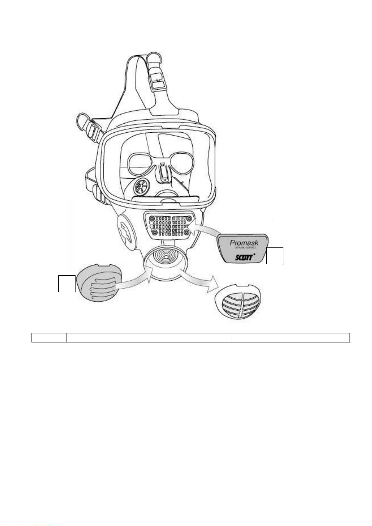
Promask
oUse as filter mask together with a Pro2000 filter (gas, particle or combined filters). The filters are
thread filters conforming to the European standard EN 148-1.
oUse with a blower device, with the filters fitted to the blower device.
oMaterial: Mask made of butyl-EPDM (Procomp) or silicone. Inner mask made of TPE or silicone.
Promask2
oUse as filter mask together with Pro2filters (2 pcs, bayonet connection).
oMaterial silicone.
2. Limitations of use
2.1 The filtering device must not be used if the environment and contamination is unknown. In case of
doubt, isolating respirators (air supply) which function independently of the atmosphere must be
used.
2.2 The filtering device must not be used in confined spaces (e.g. cisterns, tanks) because of the risk of
oxygen deficiency or presence of heavy oxygen-displacing gases (e.g. carbon dioxide).
2.3 The filtering device may be used only if the oxygen content of the air is 18–23 vol.%.
2.4 Gas filters do not protect against particles. Similarly, particle filters do not provide protection against
gases or vapours. In case of doubt, use combined filters.
2.5 Normal filtering devices do not protect against certain gases such as CO (carbon monoxide), CO2
(carbon dioxide) and N2(nitrogen).
2.6 Particle filters are only allowed for single use if they are applied against radioactive agents or micro-
organisms (virus, bacteria, fungi and spores).
2.7 It is likely that adequate protection cannot be guaranteed if the user’s beard, hair, spectacle frames
or clothing intrude into the faceseal. With the Promask one can use special spectacles (see 012790
spectacle frame).
2.8 When a breathing protector is used in explosive atmospheres, please follow the instructions given
for such areas.
2.9 Gas filters shall be replaced when the user begins to sense odour, taste or irritation. Filters used
against detrimental gases that do not display any significant indications, require special regulations
for the duration of use and correct usage.
Particle filters must be replaced at the latest when breathing resistance becomes too high.
2.10 The weight of filter used with a full face mask shall not exceed 500 g.
The Promask is used with one filter only (the other opening on the mask is blocked by the
manufacturer).
The Promask2is used with Pro2filters. Always use two filters of the same type and class, always
replace both filters at the same time.
With a blower device
2.11 The blower must be running while using the respirator. If the blower turns off by accident, the
device ceases to function as a respirator, and carbon dioxide levels may instantly rise. This is
considered an exceptional situation.
2.12 At a very intense working pace, the pressure in the facepiece can change into negative pressure at
peak inhalation.
2.13 Protection levels may be reduced if wind speed exceeds 2 m/s.
2.14 Filters must not be fitted directly to the breathing hose.

11
3. Selection
Promask/Promask2+ filter
Breathing protector equipped with filter
Type of protective device
Multiples of threshold concentration **)
Remarks, limitations
APF (Assigned protection factor)
BS 4275 (GB)
BGR 190-ZH1/701 (DE)
Full face mask with particle filter P3
40
400
Particles
Full face mask with gas filter *)
20
400
Filter types A, B, E, K, AX, SX, Hg-P3 and
NO-P3 have different applications. For more
information, see Instructions for Use of Scott
Health & Safety filters.
Device with combined filter
The specified multiples of threshold value for the gas or particle
filters are given separately, but in all cases the lowest value applies
*) Provided that the maximum permissible detrimental gas concentration for the gas filter is not exceeded.
For non-powered filtering devices with gas filter, concentration must not exceed 0.1 vol.% in gas filter
class 1 and 0.5 vol.% in gas filter class 2 and 1.0 vol.% in gas filter class 3.
**) If national guidelines exist: in all cases the lowest value applies.
Promask + blower device
Blower-assisted breathing protector equipped with filter
Type of protective device
Multiples of threshold concentration **)
Remarks, limitations
APF (Assigned protection factor)
BS 4275 (GB)
BGR 190-ZH1/701 (DE)
Power-assisted full face mask with
particle filter TM3P
40
500
Power-assisted full face mask with
gas filter *)
TM3 gas filter class 1, 2 or 3
40
500
For devices with combined filter apply the
relevant limitations of gas and particle filters.
Device with combined filter
The specified multiples of threshold value for the gas or particle
filters are given separately, but in all cases the lowest value applies.
*) Provided that the maximum permissible detrimental gas concentration for the gas filter is not exceeded.
For power-assisted filtering devices with gas filter, concentration must not exceed 0.05 vol.% in gas filter
class 1 and 0.1 vol.% in gas filter class 2 and 0.5 vol.% in gas filter class 3.
**) If national guidelines exist: in all cases the lowest value applies.
4. Preparations for use, and Donning
See Instructions for Use of the filter and blower device to be used.
Check before use
intactness of facepiece, rubber parts and visor
head harness condition and elasticity
that speech diaphragm is in place
that exhalation valve is in place and that its cover is properly fastened
that inh. and exh. valves function properly
that the filter is correct for the intended use. Filter type and class are evident from the
marking.
that storage period of the filter has not been exceeded
filter condition and intactness. Shake the filter to ensure that there are no loose
components/contents. The filter shall be replaced if it has been exposed to excessive force
or impact. It may be damaged.
With a blower device
Check adequate air flow (see Instructions for Use of the blower unit).

12
4.1 Fitting of the filter
Promask + Pro2000: Remove eventual safety plugs from the filter. Screw the filter tightly in
the connector of the mask (=inh. valve body).
Promask + Pro2000 + blower device: Screw the filters to the blower device and fix the
breathing hose to the connector of the mask.
Promask2+ Pro2: Align the bayonets on the mask with the slots on the filter and locate the
filter. Turn the filter clockwise ¼ turn The filter is tight only when the aligning marks (◄)
are opposite each other and the openings of the splash guards face backwards.
4.2 When needed, connect the spectacles to the inner mask and adjust their position.
4.3 A sweat band is recommended to control excessive hair.
4.4 Loosen the head harness straps.
4.5 Locate the chin pocket of the mask properly on the chin and pull the head harness over the
head.
4.6 Check that the chin is in the chin pocket. Tighten the straps. Start with neck straps, pull
backwards (not outwards). Then adjust the temple straps and finally the upper strap. The
cradle/net lies centered on the back of the head.
Check that the faceseal touches the skin all around, especially under the chin pocket. Try
moving the mask sideways to verify that there is no slippage.
4.7 Check tightness of the mask (two alternative methods):
Cover the exhalation opening of the mask with your hand. Exhale gently to create
overpressure. There must be no leakage between the face and the faceseal.
Cover the filter openings with your hand. Inhale to make the mask press onto your face.
If you fail to get a tight fit (=potential leakage), adjust the head harness and filter, or use
another size of the mask.
5. Maintenance and storage
5.1 Test for function and leak-tightness
If components have been replaced (visor, valve discs or speech diaphragm), a test for function
and leak-tightness must be carried out with an appropriate test device (e.g. Pro-Tester, code
141080). The test is also done in case of a mask stored unused for a longer period, and at least
once a year.
Check also that the faceblank has maintained its shape, the head harness is reasonably elastic,
the visor and the faceseal are undamaged, and that the valve discs and the speech
diaphragm’s O-ring are good and well in position. Damage must be repaired.
5.2 Replacing the visor
The visor is available in polycarbonate or polycarbonate with a chemical-resistant and scratch-
proof coating. The material code is found at the left edge of the visor. Replace visor if
damaged, dirty or scratched.
Material code is shown by an arrow:
1 (not in use)
2 hard coated polycarbonate (HC)
3 (not in use)
F polycarbonate (PC)

13
Unscrew the screws (Torx 20), loosen the visor frames, and remove the visor (Fig. A)
Place a new visor in the faceblank (with the marking ”UP” on the visor showing upwards).
Align the check marks of the visor and faceblank with each other (Fig. B).
Position the visor frames and tighten both screws (Fig. C).
Carry out the leak-tightness test (point 5.1).
5.3 Replacing the exhalation valve disc
Pull out the valve cover (Fig. D).
Separate the disc (yellow) from the valve body (pinch on the edge of the disc) (Fig. E).
Replace the disc. Press lightly on the tip of the disc to secure a good fit (Fig. F).
5.4 Replacing the inhalation valve discs
Remove the rubber valve seat by pushing it with a finger from the inside of the mask (Fig.
G).
Replace the disc (pass the tail through the central hole to the inside of the mask) (Fig. H).
Put the valve seat back to the bottom of the valve body (Fig. J). Do not press too tight (the
disc comes immobilised) because the disc must be free to move.
The valve discs of the inner mask are replaced similarly. Make sure that the rubber edge of
the inner mask comes in the valve seat groove.
5.5 Replacing the speech diaphragm
Remove the inner mask from around the speech diaphragm (Fig. K).
Press the clip to remove the speech diaphragm (Fig. L–M). To make assembly easier,
moisten the O-ring with water. Press the speech diaphragm into place.
Insert inner mask into place.
5.6 Replacing the harness buckle
Press the buckle downwards (Fig. N).
Hold the buckle and twist the rubber endpiece through the gap to the other end of the
buckle (Fig. O–P) (the buckle rotates 180 ).
Remove the buckle (Fig. Q).
Assemble in reverse order.
5.7 Replacing the inner mask
Remove first the inhalation valve seat by pushing it with a finger from the inside of the
mask (Fig. G).
Gently pry open the hole on the fastening ring of the inner mask, using a screwdriver (via
the inh. valve body opening) until the fastening ring comes off (Fig. R).
Remove the inner mask (Fig. S).
When assembling, insert the notch of the fastening ring into the tip of the exhalation valve
(Fig. T) and press the inner mask into place.

14
5.8 Cleaning
Remove the filter/filters, valves, spectacle frame, speech diaphragm and inner mask. Also
eventual breathing hose.
Clean the facepiece and components with a damp cloth or sponge, using lukewarm water
and mild detergent (neutral, pH 6-8) (e.g. washing-up liquid). A brush can be used for
stubborn dirt (be careful not to scratch the visor).
Do not use solvents (e.g. alcohol, acetone, turpentine), hot water or bleaching agents
(perborate, percarbonate).
5.9 Disinfection
After cleaning, disinfect the inside/faceseal with a disinfection solution (e.g. Scott Trigene),
rinse and allow to dry. Finally, reassemble the mask.
5.10 Storage
Storage protected from direct sunlight, at -10...+50 °C and relative humidity (RH) under 75
% (sealed filters RH max. 95 %). A properly stored, unused mask stays in good condition
for a long storage period.
The components should not be more than 12 years old.
Before use, the mask must undergo a function test, see Table.
After use, an opened filter must be sealed tightly if it is to be reused, but it must be
replaced within 6 months at the latest.
5.11 Disposal
Masks (without filters) are coarse waste. A very contaminated mask as well as used filters
are special refuse and shall be disposed of according to the filtered substances (gases or
particles).
5.12 Australia and New Zealand
For complete national requirements, please refer to the standard AS/NZS1715:2009, Use &
Maintenance of Respiratory Products.
Component
Work to be done
Intervals
Before
use
After
use
Every
year
Every 6
years
Mask,
complete
Cleaning
Disinfection
Test for function and leak-tightness/Pro-Tester
Pre-use check done by the user, according to
point 4
Replace: visor, head harness, buckles, inner
mask and other parts
■
■
■
■
■*)
■*)
■
■
■
Valve discs
(7a, 7b, 7c)
Check
Replace
Check tightness of exh. valve disc/Pro-Tester
■
■*)
■
■
■
■
Inhalation
valve
Check valve seat (part 6a)
■
■
Speech
diaphragm (8)
Check
Replace
■
■
■
*) when needed
Scott Health & Safety Oy
P.O.BOX 501
FI-65101 Vaasa, Finland
TECHNICAL SUPPORT & SALES
Tel. +358 (0)6 3244 543 or 544 or
535 Fax +358 (0)6 3244 591
www.scotthealthsafety.com
This manual suits for next models
1
Table of contents
Other Scott Respiratory Product manuals

Scott
Scott SKA-PAK AT Installation and operation manual

Scott
Scott 2 Troubleshooting guide

Scott
Scott RIT-PAK III Manual

Scott
Scott AV-3000 Service manual

Scott
Scott Profile2 User manual

Scott
Scott M98 Small User manual

Scott
Scott CEN-PAQ User manual

Scott
Scott M95 User manual

Scott
Scott Sigma 2 User manual