Simultalk 24G Wireless Features
1 www.eartec.com.com
Full duplex, two-way transceiver
State of the art 2.4GHz digital technology
No license required
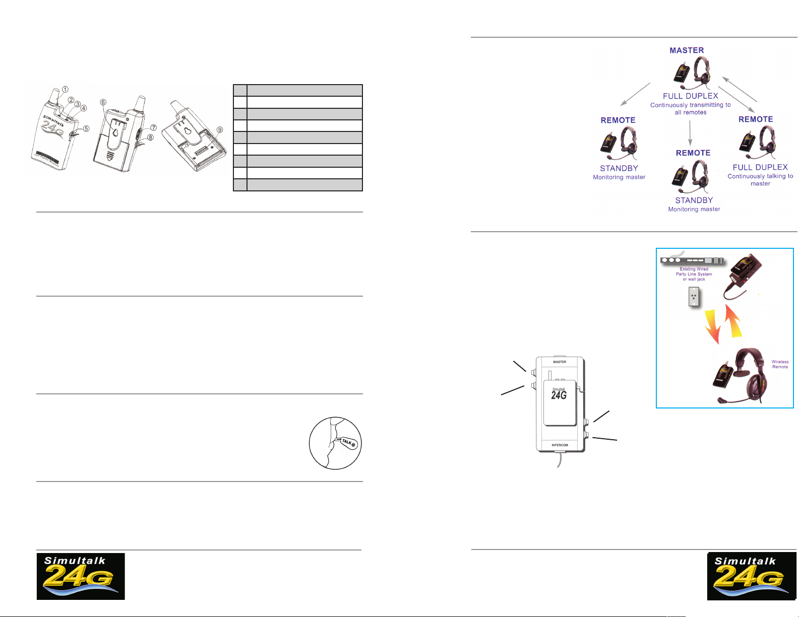
1 Antenna
2 ower ON Indicator
3Status Indicator
4 Talk Button
5 Headset Socket
6 Belt Clip
7 ON/OFF Volume Control Knob
8 Charger Socket
9 Radio Channel Dip Switch
Simultalk 24G Wireless Instructions
Charging the Radios
The batteries that provide power to your system do not need to be “drained”. Simply follow the procedure below within 48
hours before each use:
1. All radios should be OFF.
2. Plug AC Charger/Adapter into a wall outlet and attach to Radio Charging Jack.
3. Charge each radio for 6 hours.
4. To prevent overheating of the charger and to prevent damage to the charge circuit do not leave the charger plugged in
for more than 12 hours. A fully charged battery will operate in full duplex up to 4.5 hours and up to 8 hours switching to
standby mode periodically.
www.eartec.com 2
Simultaneous tal , hands free
Certified for worldwide use
Identify Your Radios
1. MASTER radio will be programmed to CONT NUOUS TALK.
-Press talk button to power ON radio
-Left light: red indicates power ON
-Right light: green indicates transmit only, receiver muted
-Right light: amber indicates transmitting and receiving
2. REMOTE radios will be programmed to CONT NUOUS RECE VE.
-Press TALK button to power ON radio
-Left light: red indicates power ON
-Right light: red indicates receive only, mic muted
-Right light: amber indicates transmitting and receiving
NOTE: To communicate properly, all ra-
dios in the group must be set to the same
frequency. The dip switch channel pro-
gramming feature is located inside the
battery compartment. See insert for chan-
nel combinations.
Using Your Radios
1. Charge radios as indicated above.
2. Plug headset jack into headset socket. Turn the volume ON. Position headset microphone directly in front of mouth.
IMPORTANT NOTE: Eartec headsets include a special noise cancelling microphone that pro-
vides digital voice translation. For optimum performance adjust microphone boom so the ele-
ment is directly in front of, and approximately 1 inch from the user’s mouth.
Simultalk 24G Wireless System Setup
For Systems with 2 Radios
1. Charge radios as indicated.
2. dentify MASTER radio, and turn it on.
3. Set MASTER radio to transmit by pressing the talk button once, and confirm amber LED light.
4. Turn on REMOTE radio. LED light should be red, indicating standby mode.
5. Set REMOTE radio by pressing the talk button once,
and confirm amber LED light.
6. You are ready to communicate.
The Simultalk 24G Pro Series is a multi
station team communication system. Each
Pro Series intercom provides the master
hands free voice contact with an unlimited
number of remote stations. All remotes
continuously monitor the master. One at a
time, remote users can switch from
standby (listen only) to continuous talk op-
eration.
1. Charge radios as indicated above.
2. dentify MASTER radio, and turn it on.
3. Set MASTER radio to transmit by press-
ing the talk button once, and confirm
amber LED light.
4. Turn on REMOTE radios. LED light
should be red, indicating standby mode.
5. Any REMOTE user may switch to trans-
mit by pressing the talk button. Light will
turn amber.
6. REMOTE users should switch from
transmit back to standby mode after con-
versation is complete. This allows another
REMOTE user to switch to transmit mode.
1. Charge radios as indicated.
2. dentify MASTER radio / interface, and turn it on.
3. Set Volume on MASTER radio to 25%.
4. Connect SLTi interface to party line in any wired beltpack location.
5. Balance wireless audio levels with the adjustments outlined below.
Note: to increase or decrease audio levels you must push and hold button for one second and then release. Continue fol-
lowing this procedure until desired audio balance is reached. Audio is increased and decreased in digital steps.
Increases audio
from wired intercom
system to wireless
remote
Decreases audio
from wired intercom
system to wireless
remote
Increases audio
from wireless re-
mote to wired inter-
com
system
Decreases audio
from wireless re-
mote to wired
intercom
system
The SLTi system allows addition of full duplex wireless head-
sets to most popular wired intercoms without complicated
and expensive base stations. The complete system consists
of a Simultalk 24G master transceiver, interface module, and
remote Simultalk 24G radios with headset. The interface in-
cludes a software driven circuit that matches the audio levels
if the wireless to that of the wired intercom.
The remote wireless user communicates with the wired party
line in a full duplex simultaneous talk format just as though
they were connected with an actual cable.
How it Works:
For Systems with 3 or More Radios
For SLTi Systems - Wired to Wireless Interface