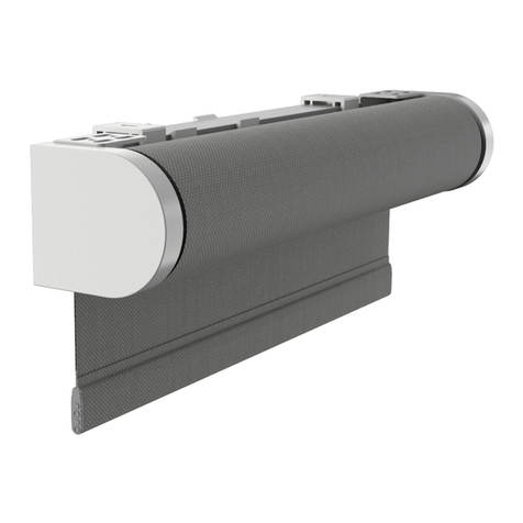
Screen Innovations Sail User manual

1- 03.2018
Sail
Installation manual
SCREEN INNOVATIONS


SCREEN INNOVATIONS- INSTALLATION MANUAL- SAIL
Rev. 1 - 03.2018 1 of 28
WELCOME
Dear Installer
This manual contains advice for a rapid and precise installation of the various
components. Although we are sure that you know how to use our products we still
recommend that you read our instructions carefully.
We always welcome any suggestions on possible improvements to the installation
techniques or the layout of the manual.
We would also remind you that during installation you should always use materials
that best comply with the environmental conditions.
It is also good practice to issue a final declaration of correct installation
according to the specifications in the manual, in addition to the mandatory declarations
of conformity required by law, where requested.
Sail is a Screen Innovations Product.
All technical interventions necessary for the installation must be carried out by
authorized and specialized technicians.
All unauthorized interventions (tampering, technical modification etc.) during the warranty
period will invalidate said warranty.
Screen Innovations. reserves the right to make technical modifications to the
components or products, except for the main features, at any time and without prior
notice.
2
2
2
2
3
3
3
4
INDEX
Symbols
General Precautions
General safety precautions
Precautions and warnings
Preliminary checks
Disposal of packaging materials
Reassembly
Material check, unpacking and preparation
Versions and packing 5
1 Base preparation 6
2 Assembling the pole 8
3 Assembling the roller tube group 10
4Electrical connections 21
5Motor programming 24
6Anemometer programming 25
26
27
7 Awning cover
Data sheets
Calculation of wind resistance based on the loads and the
anchors 28

2 of 28 Rev.1 - 03.2018
SYMBOLS
SYMBOLS
The symbols indicated are used to draw the attention of the installer to arguments of particular
importance for the safety of persons, the product or to indicate particular operating conditions.
Attention: general operating note
Attention: greater attention to what you are reading
Attention: general hazard; possible risk of damage to persons, property, components
Attention: risk of electrical hazard
Attention: risk of crushing hands
Contact: Screen Innovations or the authorised retailer
GENERAL PRECAUTIONS
Before undertaking any assembly, maintenance or cleaning operations, make sure
that you have fully understood the instructions in this manual.
Failure to respect the regulations contained herein relieves Screen Innovations of
all responsibility for damage caused to persons, animals, property and/or
components.
The installation personnel must scrupulously comply with the local accident
prevention regulations in force.
All electrical connections for movement, installation of automation accessories
etc. must only be made by qualified personnel.
If the structure is motorised and installed at a height of less than 250 cm from the ground, the
control button must be of the ‘dead-man’ type and the opening and closing operations must be
clearly visible.
In the case of any incompatibility, contact Screen Innovations
GENERAL SAFETY WARNINGS
Sail is designed for a specific use (as outlined in this manual); any use other than that envisaged shall
relieve Screen Innovations of any responsibility.
When using the awning it is good practice to remember that all moving parts can be a source of
danger.
It is compulsory to cut off the power supply (if present) when carrying out an installation,
maintenance, repair or adjustment intervention.
It is recommended that a caution sign be placed on the power supply master switch with
the following indications:
“Attention! Do not touch. Service personnel at work”.
PRECAUTIONS AND WARNINGS
The maintenance and installation personnel (installers, electricians etc.) must have sufficient
expertise and psychophysical and attitudinal requirements for undertaking the tasks at hand.
Always check the correct mounting and working efficiency of the electrical and manual drives
during the assembly.
In case of anomalies, immediately stop the work and contact the service
department of Screen Innovations
The use of non-original spare parts, or unauthorised interventions or
modifications shall relieve Screen Innovations of any responsibility for damage
caused to persons, animals or property. It is absolutely forbidden to tamper with
the fixings, the supports, the guides, the fixtures, the command and idler units
and any other component of the Sail.

Rev.1 - 03.2018 3 of 28
SYMBOLS
PRELIMINARY CHECKS
On receipt of the packed goods and before starting their assembly, check the integrity of the
material and the presence of all the components necessary for the installation.
Carefully follow the information contained in the “Material check, unpacking and preparation”
section.
In case of anomalies immediately contact the authorised retailer or Screen Innovations
DISPOSAL OF PACKAGING MATERIALS
Divide the various packaging according to the material used (cardboard, nylon, polystyrene etc.)
and dispose of them separately in compliance with the regulations in force.
REASSEMBLY
IF THE AWNING HAS TO BE MOVED, IT MUST BE DISMANTLED AND PACKED AS ORIGINALLYRECEIVED.THEREFORE,
REPEATALL THE ASSEMBLYOPERATIONS IN REVERSE ORDER,TO AVOID LOSING THE SYNCHRONY OF MOVEMENTS
AND/OR DAMAGING COMPONENTS, SO THATTHE SUBSEQUENT REASSEMBLYOPERATIONS CAN BE
PERFORMED CORRECTLYAS DESCRIBED IN THIS MANUAL. SCREEN INNOVATIONS WILL NOTBE LIABLE FOR ANY
FAILURES ARISING FROM INCORRECT DISASSEMBLY.
SCREEN INNOVATIONS- INSTALLATION MANUAL- SAIL

4 of 28 Rev.1 - 03.2018
MATERIAL CHECK, UNPACKING AND PREPARATION
NOTE:
Fixing elements such as screws and anchors are not included and must be
chosen by the installer based on the type of fixture foreseen (wall, wood, metal
etc.).
Proceed as follows:
- Remove the contents from the packaging.
8BSOJOH
Do not use a knife to avoid the risk of ruining the paint or metal elements or the
canvas fabric.
Warning:
all references to theright-hand or left-hand sideintheassembly gures apply when
looking at thestructurewith theback against theshaped pole.
Warning:
Theelectrical system controlling theawning isthecustomer’sresponsibility and
must beinstalled by qualied personnel incompliancewith current regulations.
SCREEN INNOVATIONS- INSTALLATION MANUAL- SAIL
RH LH

Rev.1 - 03.2018 5 of 28
WEIGHTS AND DIMS
3FG $POUFOUT )&*()5in 8*%5)in %FQUIin 8FJHIUlb
1 Shaped pole and accessories 10'' 25'' 94.5'' a102
2 Pedestal 3.5'' 42.5'' 42.5'' a93
NBYin NJOin %FQUIin 8FJHIUlb
3 Roller tube pre-fitted with canvases 10.5'' 10.5'' 203 a84
C
B
H
A
DG
E
F
1
2
3
ABCDE FGH
210.25'' 133.875' 133.875'' 89.75'' 133.25'' 107.75'' 101'' 204.75
SCREEN INNOVATIONS - INSTALLATION MANUAL - SAIL

6 of 28 Rev.1 - 03.2018
BASE PREPARATION 1
'JH
Use a spirit level to check that the base (A) is perfectly flat once in position.
'JH
Position the eight ballast tiles (B) (not supplied) in the respective seats in the base (A).
NOTE: Use 20x20x1 in tiles weighing at least 46 lbs each.
A
A
B
NOTE: Base is optional, pole can be mounted directly to the ground.
NOTE: Appropriate anchors must be specified if securing directly to the ground (see page 28)

Rev.1 - 03.2018 7 of 28
1 BASE PREPARATION
'JH
Position the cover (C) on the ballasted base.
Route the heaving line through the central hole (D) of the cover.
C
D
SCREEN INNOVATIONS - INSTALLATIONMANUAL - SAIL
NOTE: Base is optional, pole can be mounted directly to the ground.
NOTE: Appropriate anchors must be specified if securing directly to the ground (see page 28)

8 of 28 Rev.1 - 03.2018
ASSEMBLING THE POLE 2
'JH
Insert the power cable from the shaped pole (A) into the vertical support pole (B). Bind the heaving
line and the power cable together using insulating tape.
5IFDVTUPNFSJTJODIBSHFPGDPOOFDUJOHUIFQPXFSTVQQMZUPUIFMJHIUTJGöUUFEBOEUPUIF
SFNPUFDPOUSPMNPUPS5IFTZTUFNNVTUCFJOTUBMMFECZRVBMJöFEQFSTPOOFMJODPNQMJBODF
XJUIDVSSFOUSFHVMBUJPOT
'JH
Insert the shaped pole (A) into the vertical support pole (B), locking it using the knob (C).
The task of the knob (C) is to prevent the shaped pole from rotating.
C
B
A
A
B
C
SCREEN INNOVATIONS - INSTALLATION MANUAL - SAIL

Rev.1 - 03.2018 9 of 28
2 ASSEMBLING THE POLE
'JH
Lift the vertical support pole (A) and rest it in correspondence with the relative holes on the
assembled base (B) or on the ground, and simultaneously pull the heaving line (E) until the power
cable comes out of the base (B). Fasten the pole using the relative screws provided.
NOTE: Ifassembling ona base, theknob (D) must alwaysbeturnedaway from theside
wherethepower cablecomes out (E).
B
A
D
E
'JH1PMFBTTFNCMZPOHSPVOE
If Sail is fastened directly to the ground, mark out the holes using the plate of the pole
(A) as a template, drill into the ground using a suitable bit and fasten the pole using
suitable anchors.
A
SCREEN INNOVATIONS - INSTALLATION MANUAL - SAIL

10 of 28 Rev.1 - 03.2018
ASSEMBLING THE ROLLER TUBE GROUP 3
'JH
Take the roller tube arm out of the packing and fasten it to the bracket of the shaped arm.
5BLFDBSFXJUIUIFQPTJUJPOPGUIFi61wQMBUFPOUIFESVNXIJDINVTUCFBUUIFUPQBOEDMFBSMZMFHJCMF
Insert the recessed and drilled side of the central arm (A) in correspondence with the drilled plate (B) on the shaped pole.
NOTE: TWO PEOPLE ARE RECOMMENDED FOR THESE OPERATIONS.
BA
SCREEN INNOVATIONS - INSTALLATION MANUAL - SAIL
UP
UP

Rev.1 - 03.2018 11 of 28
3 ASSEMBLING THE ROLLER TUBE GROUP
'JH
Insert the fastening screw provided (A).
A
RH
LH
SCREEN INNOVATIONS - INSTALLATION MANUAL - SAIL

12 of 28 Rev.1 - 03.2018
ASSEMBLING THE ROLLER TUBE GROUP 3
'JH
Attach the central upper rope (A) to the upper hole on the fitting (B) at the end of the roller tube
pole (C).
C
RH
LH
B
A
'JH
Cut the two WHITE ties (A) binding the left side arm (B) SIMULTANEOUSLY.
NOTE: Two operatorsarerequired for thisoperation.
B
A
A
RH
LH
SCREEN INNOVATIONS - INSTALLATION MANUAL - SAIL

Rev.1 - 03.2018 13 of 28
3 ASSEMBLING THE ROLLER TUBE GROUP
'JH
Release the spring clip (A) at the end of the rope (B) from the eyelet of the left-hand awning (C).
Insert the recessed and drilled side of the side arm (D) in correspondence with the drilled plate (E)
on the left-hand side of the shaped pole and tighten using the screw provided.
D
B
A
C
E
RH
LH
SCREEN INNOVATIONS - INSTALLATION MANUAL - SAIL

14 of 28 Rev.1 - 03.2018
ASSEMBLING THE ROLLER TUBE GROUP 3
'JH
Join the coupling element (A) of the upper side rope (B) in the upper attachment plate at the end
of the side arm (C).
'JH
Join the coupling element (A) of the side rope (B) in the side attachment plate at the end of the
left side arm (C).
NOTEUIFUJHIUFOFSJODBCMF#IBTBMSFBEZCFFOBEKVTUFEBOEUFTUFETPEP/05BMUFS
UIFBEKVTUNFOU
CC
A
B
RH
LH
A
B
RH
LH
A
B
C
SCREEN INNOVATIONS - INSTALLATION MANUAL - SAIL

Rev.1 - 03.2018 15 of 28
3 ASSEMBLING THE ROLLER TUBE GROUP
'JH
Fit the block (A), as shown in the callout, in the eyelet (B) of the shaped pole on the left-hand side.
A
B
D
E
RH
LH
NOTE: Reconnect thehook (D) to theeyelet oftheleft-hand awning (E).
SCREEN INNOVATIONS - INSTALLATION MANUAL - SAIL

16 of 28 Rev.1 - 03.2018
ASSEMBLING THE ROLLER TUBE GROUP 3
'JH
Release the spring clip (B) at the end of the rope (C) from the eyelet of the right-hand canvas (D).
D
C
B
'JH
Cut the two BLACK ties (A) binding the left side arm (B) SIMULTANEOUSLY.
NOTE: Two operatorsarerequired for thisoperation.
A
A
B
RH
LH
SCREEN INNOVATIONS - INSTALLATION MANUAL - SAIL

Rev.1 - 03.2018 17 of 28
3 ASSEMBLING THE ROLLER TUBE GROUP
'JH
Insert the recessed and drilled side of the right side arm (A) in correspondence with the drilled
plate (B) on the shaped pole and tighten using the screws provided.
'JH
Join the coupling element (A) of the upper side rope (B) in the upper attachment plate at the end
of the side arm (C).
A
B
C
B
A
SCREEN INNOVATIONS - INSTALLATION MANUAL - SAIL

18 of 28 Rev.1 - 03.2018
ASSEMBLING THE ROLLER TUBE GROUP 3
'JH
Join the coupling element (A) of the side rope (B) in the side attachment plate at the end of the
side arm (C).
NOTEUIFUJHIUFOFSJODBCMF#IBTBMSFBEZCFFOBEKVTUFEBOEUFTUFETPEP/05BMUFS
UIFBEKVTUNFOU
B
A
C
SCREEN INNOVATIONS - INSTALLATION MANUAL - SAIL
Table of contents
Other Screen Innovations Indoor Furnishing manuals

Screen Innovations
Screen Innovations Nano 375 Box User manual

Screen Innovations
Screen Innovations Nano Roll 275 Series User manual

Screen Innovations
Screen Innovations Nano Box User manual

Screen Innovations
Screen Innovations Nano Box User manual

Screen Innovations
Screen Innovations Zen Roll User manual

Screen Innovations
Screen Innovations Nano Roll 275 Series User manual

Screen Innovations
Screen Innovations Nano Roll 375 Series User manual

Screen Innovations
Screen Innovations Zen Box User manual

Screen Innovations
Screen Innovations Nano Box User manual

Screen Innovations
Screen Innovations Nano Roll 275 Series User manual