SDT International SDT340 User manual

SDT International sa-nv • Bd de l’Humanité 415 • B-1190 Brussels (Belgium) • Tel: +32(0)2 332 32 25 • email: info@sdtultrasound.com
SDT North America • 1532 Ontario Street, Cobourg, ON • Phone: 1-800-667-5325 | 1-905-377-1313 •email: hearmore@sdtultrasound.com
www.sdtultrasound.com
Asset Health Evaluation Meter
USER MANUAL
December 2018. Version 1
© SDT International. All rights reserved. Specifications are subject to change without notice.

MAN.340.EN--01--SDT340-user-manual-Eng.docx
2/30
1. Safety .............................................................................................................4
2. Caution...........................................................................................................4
3. Introduction ...................................................................................................5
4. Unpack ...........................................................................................................5
5. Battery ...........................................................................................................5
6. Controls and connections ..............................................................................7
6.1. Power on...................................................................................................................... 7
6.2. Sleep Mode.................................................................................................................. 7
6.3. Power Off..................................................................................................................... 8
6.4. Driver ........................................................................................................................... 8
6.5. Plug & Unplug a Sensor ............................................................................................... 8
7. Home screen..................................................................................................9
8. Data Collection Modes...................................................................................9
9. Proceed with ultrasound signal acquisition in Free Mode.......................... 10
10. ST tab for ultrasound readings................................................................. 12
11. Proceed with vibration signal acquisition in Free Mode.......................... 12
12. ST tab for vibration readings.................................................................... 14
13. Display Ultrasound and Vibration Time Signal......................................... 15
14. Display ultrasound and vibration spectrum............................................. 16
15. Proceed with temperature measurement in Free Mode......................... 17
16. Tree navigation and data storage in Free Mode...................................... 18
17. Rotational speed...................................................................................... 20
18. General Settings....................................................................................... 21
18.1. System info.............................................................................................................22
18.1.1. Device info..................................................................................................................... 22
18.1.2. License info.................................................................................................................... 23
18.1.3. Last calibration date...................................................................................................... 23
18.1.4. Battery info.................................................................................................................... 23
18.1.5. Hardware info................................................................................................................ 24
18.1.6. Software info................................................................................................................. 24

MAN.340.EN--01--SDT340-user-manual-Eng.docx
3/30
18.1.7. Database........................................................................................................................ 25
18.1.8. Certifications ................................................................................................................. 25
18.1.9. Manufacturer info ......................................................................................................... 25
18.2. Language................................................................................................................ 26
18.3. Bluetooth ...............................................................................................................26
18.4. Date and hour ........................................................................................................27
18.5. Brightness ..............................................................................................................27
18.6. Network .................................................................................................................28
18.7. Theme ....................................................................................................................28
19. Recommended calibration intervals ........................................................ 29
20. Warranty.................................................................................................. 29
21. Responsibility limits ................................................................................. 30
22. Destruction and recycling of waste equipment ....................................... 30
23. Copyright.................................................................................................. 30
Figure 5-1 Recharge the battery.............................................................................................................. 6
Figure 5-2 Change the primary plug of the power supply ....................................................................... 6
Figure 6-1 Front panel ............................................................................................................................. 7
Figure 6-2 Figure 4: Lateral plates........................................................................................................... 7
Figure 7-1 Home screen........................................................................................................................... 9
Figure 9-1 Ultrasound measurement screen ......................................................................................... 10
Figure 9-2 Ultrasound Measurement Settings ...................................................................................... 11
Figure 9-3 Condition indicator, time signal and spectrum tabs ............................................................ 11
Figure 10-1 Ultrasound ST tab............................................................................................................... 12
Figure 11-1 Vibration measurement screen .......................................................................................... 13
Figure 11-2 Vibration Measurement Settings ....................................................................................... 13
Figure 11-3 Condition indicator, time signal and spectrum tabs .......................................................... 14
Figure 12-1 Vibration ST tab.................................................................................................................. 14

MAN.340.EN--01--SDT340-user-manual-Eng.docx
4/30
1. Safety
Read carefully the manual before using the SDT340. To prevent death or injury risks and a severe
damage to the unit and its accessories, use only as specified in this manual. Otherwise, the protection
provided by the instrument might be impaired. Make sure that all instructions are fully understood
and observed.
To avoid personal injury:
•Do not use if damaged.
•Use caution around rotating equipment and keep cords and straps contained.
•Select a safe location for the sensor and proceed with utmost care during its mounting when
taking readings on exposed rotating parts.
•Do not operate around explosive gas, vapor, and dust or in damp or wet environments.
•Use proper protective equipment, as required by local or national authorities, when working
in hazardous areas.
•Comply with local and national safety requirements when working in hazardous locations.
•See emissivity information for actual temperatures. Reflective objects have lower emissivity
and might pose a burn hazard.
•Never look directly to the laser beam. Never point the laser beam at a person's eye. Do not
aim the laser at specular reflection surfaces. Never look the laser using an optical instrument.
The power supply should be only operated at an ambient temperature between 0°C to 45°C up to 95%
relative humidity, no condensation. Its storage temperature is between -40°C to +70°C (-40°F to
+158°F) 10 to 95% relative humidity. The power supply should never be operated or even stored at
places listed below, because this could lead to operating failures:
•Places heavily exposed to moisture or where water condensing may occur.
•Places subject to constant vibrations or to high temperature fluctuations.
•Outdoors.
2. Caution
Do not disassemble the instrument, the sensors, the battery, the battery docking station and the
battery power supply. Do not attempt internal alterations. Do not attempt any repairs. Potential
damages will not be covered by the Lifetime Warranty. Contact SDT Ultrasound Solutions or an SDT
Authorized Service Provider.
The permissible ambient temperature range for the operation of the SDT340 is -15 °C to +60 °C (14 °F
to 140 °F). Relative humidity must be less than 90%, non-condensing.
Due to the typical self-discharge rate of NiMH batteries it is recommended to charge the battery at
least every 3 months, even if it is not used. It is recommended not to store an uncharged battery for
more than a few weeks. This would significantly reduce its life span.
Version 01 2018-12 © SDT International. All rights reserved

MAN.340.EN--01--SDT340-user-manual-Eng.docx
5/30
3. Introduction
The SDT340 is a screening and diagnostic tool for Asset Health Evaluation. The SDT340 includes the
following features:
•Ultrasound and vibration measurements
through 2 input channels
•4 Scalar indicators
•0 Hz to 50 kHz Bandwidth
•10 minutes record length
•Tree database structure
•3.5” full-color display 320x480
•On-screen time waveform and spectrum
•Spanning and expanding functions for
navigation through time waveform
and spectrum
•Signal play back
•On-board temperature and rotational
speed measurements
•256 kHz sample rate
•4.2 GB data memory
•Quick and intuitive navigation through
database nodes
•Recall of historical data in-the-field
•TWF and FFT 10 highest values table
•Off-route and on-route data collection
modes
•Bluetooth for wireless audio
streaming
4. Unpack
The items that follow are included in your purchase of the SDT340 kit. Unpack and inspect them.
•SDT340
•Wired headset
•Spiral Cable, 2 male 7-pole LEMO
connectors
•USB communication cable
•USB key containing user manuals and
UAS Lite
•Battery pack
•Battery charger, power cord, EU, US
and UK plugs
•Battery docking station
•Shoulder strap
•Multi-function screw driver
5. Battery
Caution:
Only use the docking station and the power supply provided by SDT.
Do not store an uncharged battery for more than a few weeks.
Perform preferably a complete charge cycle.
Charge the battery at least every 3 months, even not used.
The SDT340 operates on a rechargeable Nickel Metal Hydride (NiMH) battery. After you unpack the
unit, fully charge the battery pack before its first use. To charge the battery pack:
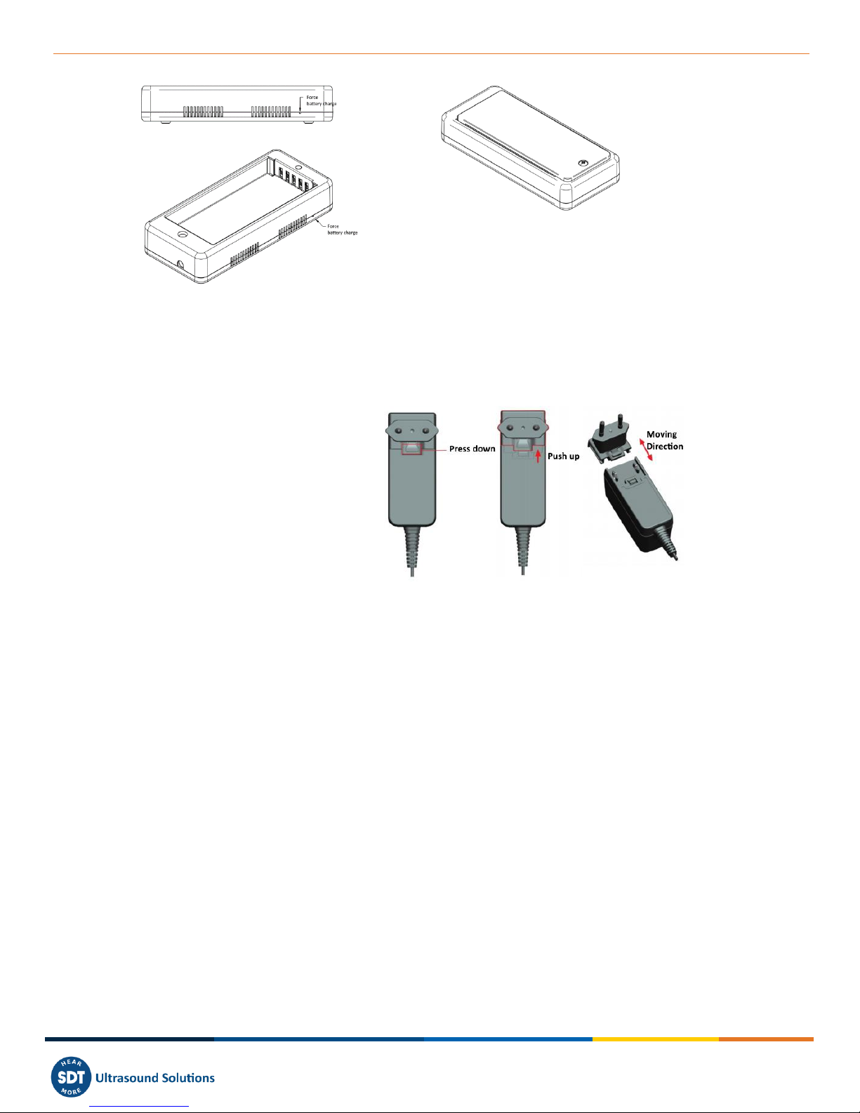
•Plug the power supply (*) to the main and connect it ❶to the docking station. Then the LED
is blinking blue.
•Loosen the quick fastener using the screw driver and remove the battery pack from the unit.
•Place the battery pack in the docking station ❸. The LED should stay on blue a few seconds
and then flash green. Otherwise, perform a force charging by inserting a needle in the reset
location ❷.
•When the LED is continuously lit green, the battery is fully charged.
Version 01 2018-12 © SDT International. All rights reserved
MAN.340.EN--01--SDT340-user-manual-Eng.docx
6/30
Figure 5-1 Recharge the battery
(*) The primary plug of the power
supply is interchangeable. The
procedure of changing is as per
the pictures.
Figure 5-2 Change the primary plug of the power supply
The color of the docking station status LED ❹shows:
•The LED flashes blue –the docking station is powered.
•The LED remains blue illuminated a few seconds when the battery is placed in the docking
station –the battery is detected.
If not, perform a force charge by inserting a needle in the force battery charge location ❷.
•The LED flashes green –the battery pack is charging.
•The LED is green lit continuously –the battery is fully charged.
•The LED flashes red –the docking station detect an abnormal current consumption or an
abnormal temperature. Disconnect and then reconnect the power supply from the main to
reset the docking station.
The SDT340 autonomy is typically 8 hours for a fully charged battery pack and the recharge time is
about 7 hours.
❶Power supply connector
❷Force battery charge location
❸Battery pack placed on the docking station
❹Docking Station LED
❸
❷
❹
❶
❷
Version 01 2018-12 © SDT International. All rights reserved
MAN.340.EN--01--SDT340-user-manual-Eng.docx
7/30
6. Controls and connections
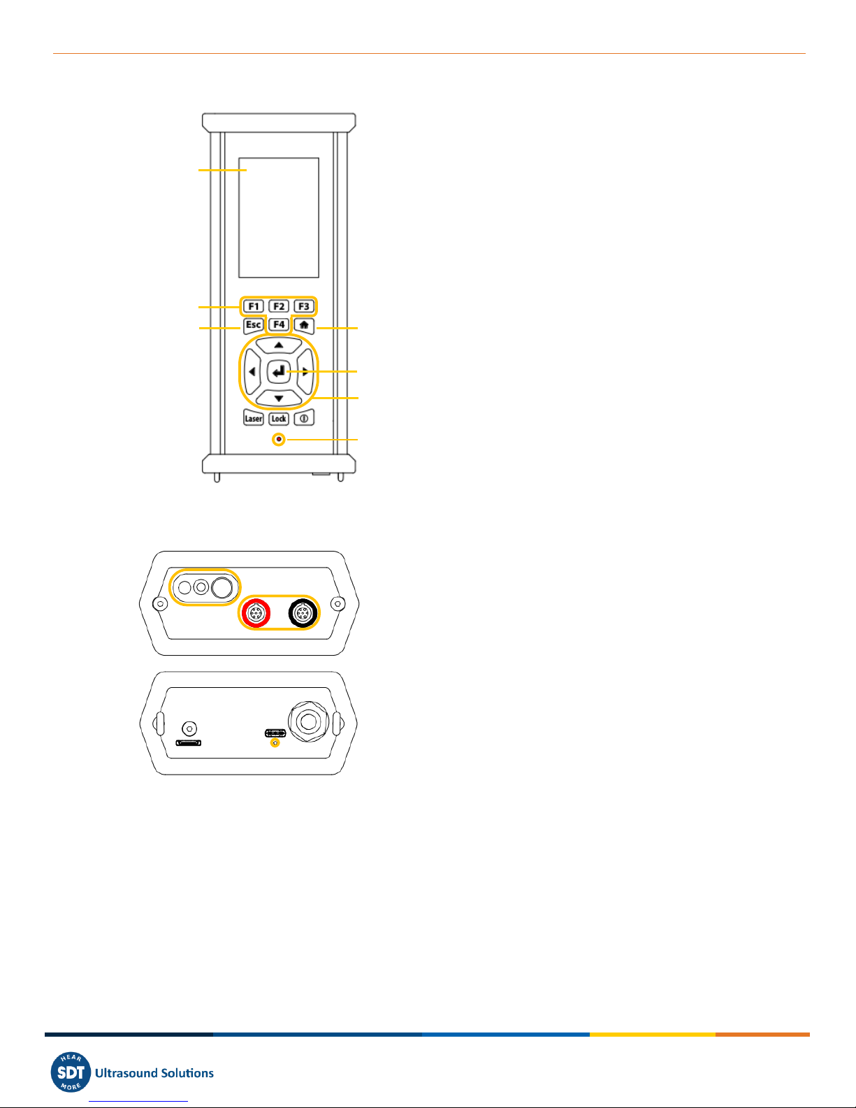
❶Display
❷F1 to F4. Their respective function is indicated
in the bottom of the display
❸Escape for stopping a signal acquisition and
going back to the previous menu through setting
screens
❹Home for displaying the main menu
❺Enter to start the acquisition and validate
changes through setting screens
❻Up, Down, Left and Right navigation keys for
the signal, audio amplification adjustment and
navigation through the settings screens
❼Hold-on laser
❽On/Off
❾Status LED.
Figure 6-1 Front panel
❿Tachometer, laser and IR thermometer
⓫Inputs channels. Black collar for ultrasound, red
for vibration. To plug a connector, line up the red
dot on the plug with the red mark on the connector.
Insert the plug into the connector without any
rotating movement. To unplug the connector, move
up, towards the cable, the ring located on the
bottom of the plug. Only pull the connector without
any rotation.
⓬Wired headset connector.
⓭USB Port.
⓮Reset location. Insert a needle, the unit will
restart.
⓯Shoulder strap rings.
Figure 6-2 Figure 4: Lateral plates
6.1. Power on
Press the Power button ❽. At power up, device information and battery charge are displayed, then
the Home menu is displayed on the screen.
6.2. Sleep Mode
❿
⓫
⓭
⓬
⓮
⓯
❶
❷
❸
❹
❼
❻
❽
❾
❺
Version 01 2018-12 © SDT International. All rights reserved

MAN.340.EN--01--SDT340-user-manual-Eng.docx
8/30
After a few minutes of inactivity, the screen is powered off for battery saving and the status LED is
blinking green. Press any key to reactivate the display.
6.3. Power Off
Press the Power button ❽. At the prompt, select Yes with the Left navigation key ❻, or No to
continue with the operation. Confirm using Enter ❺.
6.4. Driver
Caution:
Install first the driver before connecting the SDT340 to your computer.
The driver installation file is on the USB stick provided with your SDT340 kit. You can download it from
https://ftp.sdt.be/pub/Software/. The file name is SDT2xxDriverInstaller.
For Ultranalysis Suite 4.0 (UAS) Private Network and Cloud versions, the driver must be installed
individually on each computer you will use.
Log on a Windows session as an administrator. The driver must be downloaded locally on your
computer. Then, double click the file and follow the instructions.
6.5. Plug & Unplug a Sensor
The SDT340 has 2 input ports with a 7-pole LEMO connector for external sensors. The channel with the
red collar is dedicated to vibration measurement as the black is reserved for ultrasound.
LEMO connectors have a sprung-loaded knurled barrel and mechanical polarization to go only in one
way round.
To plug a LEMO connector, line up the red dot on the plug with the red mark on the connector. Insert
the plug into the connector without any rotating movement.
To unplug, move up the ring located on the bottom of the plug. Be sure to only pull the connector
without any rotation and to never pull on the cable itself.
Version 01 2018-12 © SDT International. All rights reserved
MAN.340.EN--01--SDT340-user-manual-Eng.docx
9/30
7. Home screen
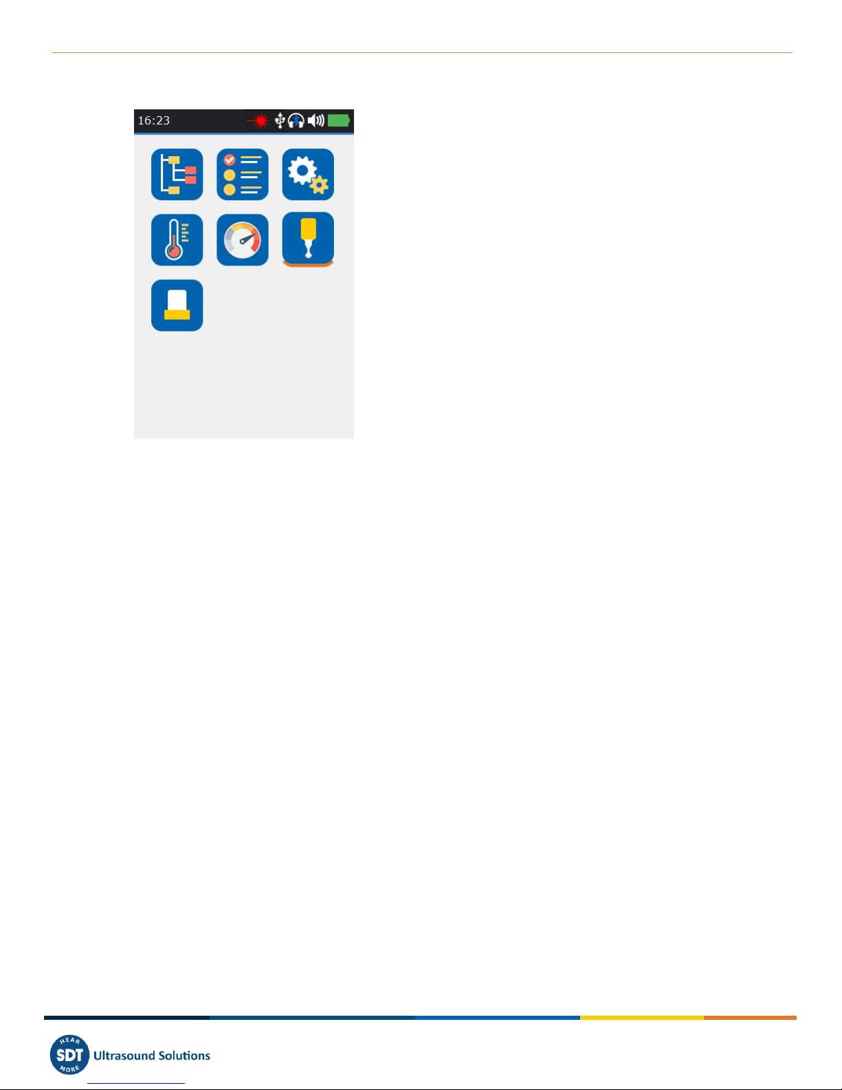
❶Tree Data Collection Mode
❷Survey Data Collection Mode
❸General Settings
❹Temperature
❺Rotational speed
❻Ultrasound contact sensor
❼Accelerometer
❽Bottom orange line indicates which icon is
currently selected
❾Time and date scrolling information
❿Laser, USB, wireless, wired headset and
remaining battery charge icons
Figure 7-1 Home screen
The Home screen is displayed after the device power up.
On top left, date and time are scrolling ❾. On the top right, laser (when activated), USB (when the
SDT340 is connected to a computer), wireless headset (when paired), wired headset (when connected)
and battery remaining charge icons are displayed ❿.
Use the navigation keys to select an icon and press Enter to validate your choice. The selected icon is
indicated by a bottom orange line ❽.
Press Home to directly come back to the Home screen from any menu.
8. Data Collection Modes
Before recording data, you must first install the driver, create a tree structure from UAS and upload it
inside the instrument.
The SDT340 features 3 modes of data collection:
The Free mode –the user selects a sensor; the measurement settings and choose the recording
location freely inside the tree structure. If the measurement type doesn’t exist, the SDT340
dynamically creates it.
The Tree Mode (for UAS2, UAS Lite and UAS4.0 users only) –the user first selects at his own discretion
a measurement location and then select an existing measurement type. The user is not allowed to
change the measurement settings or create a new measurement type inside the tree structure.
The Survey Mode (for UAS2, UAS Lite and UAS4.0 users only) –the device proposes a filtered list of
measurements to collect in a predetermined order. The user is not allowed to change the
measurement settings or create a new measurement type inside the tree structure.
Refer to the paragraph ‘’Tree navigation and data storage in Free Mode“to see the definition of a
measurement type.
❶
❷
❸
❹
❺
❻
❼
❽
❾
❿
Version 01 2018-12 © SDT International. All rights reserved
MAN.340.EN--01--SDT340-user-manual-Eng.docx
10/30
9. Proceed with ultrasound signal acquisition in Free Mode
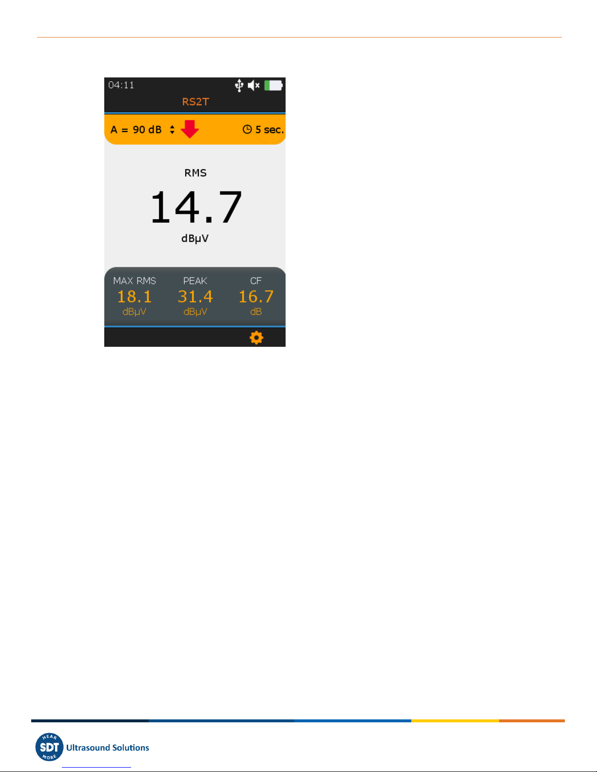
❶Sensor in use
❷Amplification
❸Amplification adjustment indicator
❹Running RMS
❺Running Max RMS
❻Running Peak
❼Running Crest Factor
❽F3 for entering the settings menu
❾Preset acquisition time
Figure 9-1 Ultrasound measurement screen
From the Home screen, select the ultrasound sensor and press Enter. Its code name ❶is confirmed
in the top of the screen.
Set up amplification from 30 to 90 dB ❷using Up and Down navigation keys till the amplification
adjustment indicator ❸disappears. Set up the audio volume with Left and Right keys.
The 4 Condition indicator running values (❹to ❼) are displayed. RMS is automatically refreshed 2
times per second. A force refresh of Max RMS, Peak and Crest Factor is manually carried out when
modifying the amplification.
The preset acquisition time ❾is displayed on top right.
❶
❷
❸
❹
❺
❻
❼
❽
❾
Version 01 2018-12 © SDT International. All rights reserved
MAN.340.EN--01--SDT340-user-manual-Eng.docx
11/30
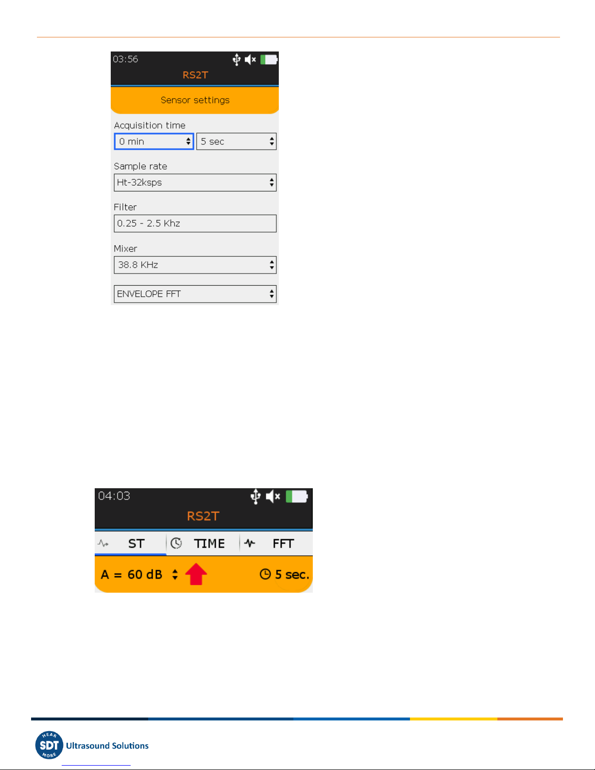
❶Sample rate
❷Acquisition time
❸Filter
❹Mixer
❺Selected field surrounded by a blue line
❻FFT or FFT Envelope
Figure 9-2 Ultrasound Measurement Settings
Press Enter to trigger the acquisition or F3 to first modify the measurement settings as the sample rate
❶from 32,000 to 256,000 samples per second (sps), the acquisition time ❷from 1 to up to 600
seconds (*) and the mixer frequency ❹only if the sample rate is 32,000 sps.
Filter ❸is automatically selected according to the chose sampling rate. Use Left and Right navigation
keys to highlight the desired field. It will be surrounded by a blue line ❺. Use Up and Down to edit
the value of the highlighted field. Choose the Envelope FFT for advanced diagnostics or a simple FFT
❻analysis using Up and Down.
Press Escape to go back to the measurement screen without applying changes or Enter to go back with
applying the modifications.
❶ST tab
❷TIME tab
❸FFT Tab
❹Blue underline showing the active tab
❺Acquisition time
Figure 9-3 Condition indicator, time signal and spectrum tabs
At the end of the acquisition time, you have access to the 4 condition indicators from the tab ST ❶,
the time signal from the tab TIME ❷and the spectrum from the tab FFT ❸. The active tab is blue
underlined ❹. Press F2 to switch between the 3 tabs.
❶
❷
❸
❹
❺
❶
❷
❸
❹
❻
❺
Version 01 2018-12 © SDT International. All rights reserved
MAN.340.EN--01--SDT340-user-manual-Eng.docx
12/30
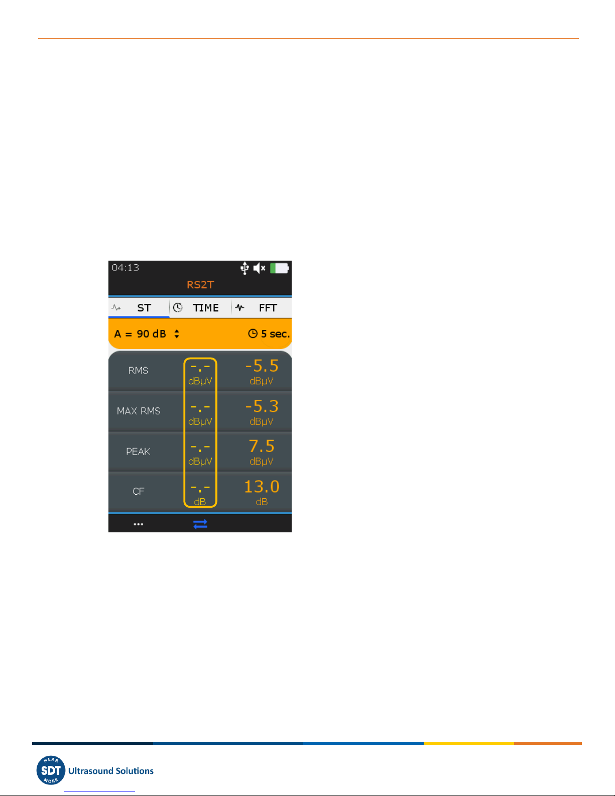
10. ST tab for ultrasound readings
At the end of the acquisition, the device displays the ultrasound condition indicator tab ST.
There, the final RMS ❶, final Max RMS ❷, final Peak ❸and Crest factor ❹are calculated from the
samples collected during the signal acquisition. The current measurement can be compared with the
previous measurement ❻.
Note than the Max RMS is the highest sub RMS observed during the acquisition time. Each Sub RMS is
calculated over a period of 250 milliseconds. The Peak value is the highest positive amplitudes of the
samples. The Crest Factor is the ratio between the Peak and the RMS. You can choose to display the
Crest factor using a natural scale or a logarithmic scale from the settings menu.
To display the time signal and then the spectrum, press F2 ❺. To record the signal, press Enter, select
the destination and confirm by Enter or press Esc to delete the signal. More details about the
navigation inside the tree structure are below.
❶Final RMS
❷Final Max RMS, the Highest of the sub RMS
calculated over 250 milliseconds
❸Final Peak
❹Final Crest Factor
❺F2 to display the time signal
❻Acquisition ❶to ❹from the previous
measurement.
Figure 10-1 Ultrasound ST tab
11. Proceed with vibration signal acquisition in Free Mode
From the Home screen, select the accelerometer and press Enter. The name ①is confirmed in the
top of the screen. The 4 Condition indicator running values (④to ⑦) are displayed. RMS vibration
velocity is automatically refreshed 2 times per second. You can choose to display the vibration velocity
in millimeters par second or in inches per second and the frequencies in Hertz or in CPM from the
settings menu. The preset acquisition time ⑦is displayed on top right.
❸
❷
❶
❹
❺
❻
Version 01 2018-12 © SDT International. All rights reserved

MAN.340.EN--01--SDT340-user-manual-Eng.docx
13/30
①Sensor in use and bandwidth
②Running Velocity RMS
③Running Acceleration RMS
④Running Peak Acceleration
⑤Running Acceleration Crest Factor
⑥F3 for entering the settings menu
⑦Acquisition time
Figure 11-1 Vibration measurement screen
Press Enter to trigger the acquisition or F3 to first modify the measurement settings as the bandwidth
①from 5 to 1,000 Hz, 10 to 1,000 Hz and 10 to 10,000 Hz, the sample rate ②from 32,000 to 64,0000
samples per second (sps) and the acquisition time ③from 1 to up to 600 seconds (32,000 sps) or 300
seconds (64,000 sps). Use Left and Right navigation keys to highlight the desired field. The selected
field is surrounded by a blue line ④. Use Up and Down to edit the value of the highlighted field.
Choose the Envelope FFT for advanced diagnostics or a simple FFT ⑤analysis using Up and Down.
Press Escape to go back to the measurement screen without applying changes or Enter to go back with
applying the modifications.
①Bandwidth
②Sample rate
③Acquisition time
④Selected field surrounded by a blue line
⑤FFT
Figure 11-2 Vibration Measurement Settings
①
②
③
④
⑤
⑥
②
①
③
④
⑦
⑤
Version 01 2018-12 © SDT International. All rights reserved

MAN.340.EN--01--SDT340-user-manual-Eng.docx
14/30
At the end of the acquisition time, you have access to the 4 condition indicators from the tab ST ❶,
the time signal from the tab TIME ❷and the spectrum from the tab FFT ❸. The active tab is blue
underlined ❹.
Press F2 to switch between the 3 tabs.
❶ST tab
❷TIME tab
❸FFT Tab
❹Blue underline showing the active tab
Figure 11-3 Condition indicator, time signal and spectrum tabs
12. ST tab for vibration readings
At the end of the acquisition, the device displays the vibration condition indicator tab ST. There, the
final Velocity RMS ①, final Acceleration RMS ②, Acceleration Peak ③and Acceleration Crest factor
④are calculated from the samples collected during the signal acquisition. The current measurement
can be compared with the previous measurement ⑥.
①Final Velocity RMS
②Final Acceleration RMS
③Final Acceleration Peak
④Final Acceleration Crest Factor
⑤F2 to display the time signal
⑥Previous measurement
Figure 12-1 Vibration ST tab
To display the time signal and then the spectrum, press F2 ⑤. To record the signal, press Enter, select
the destination and confirm by Enter or press Esc to delete the signal. More details about the
navigation inside the tree structure are below.
❹
①
②
③
④
⑤
❶
,
❷
,
❸
,
⑥
Version 01 2018-12 © SDT International. All rights reserved

MAN.340.EN--01--SDT340-user-manual-Eng.docx
15/30
13. Display Ultrasound and Vibration Time Signal
At the end of the signal acquisition and from the ST tab, press F2 to display the time signal. The TIME
tab ①is now active.
With Up and Down navigation keys zoom in and out a portion of the signal from a time scale of 10
seconds ②to 1 second. With Left and Right navigation keys, navigate between the different portions
of the time waveform.
Press F1 ③to display the list of the 10 highest values and one more time to go back to the time signal
view.
Press F2 ④to toggle to the spectrum view or Enter to store the data.
①TIME tab is active
②Zoom on 10 seconds of the
time waveform
③F1 to display the list of the
10 highest values
④F2 to display the spectrum
Figure 14: zoomed out and zoomed in time waveform
①10 highest values
②10 highest values
acquisition time
③10 highest accelerations (g)
④10 highest voltage (uV)
Figure 15: List of the 10 highest values, vibration left and ultrasound right
①
②
④
①
②
③
④
Version 01 2018-12 © SDT International. All rights reserved
MAN.340.EN--01--SDT340-user-manual-Eng.docx
16/30
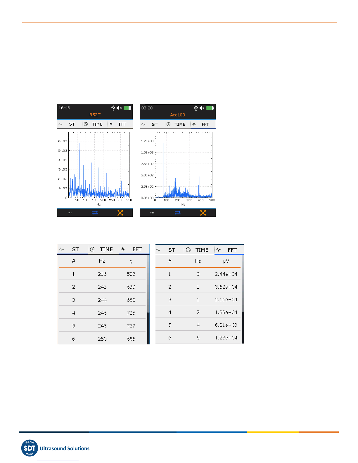
14. Display ultrasound and vibration spectrum
From the TIME tab, press F2 to display the spectrum. The FFT tab ❶is now active.
With Up and Down navigation keys zoom in and out a portion of the signal. With Left and Right
navigation keys, navigate between the different portions of the spectrum.
Press F1 ❷to display the list of the 10 highest values and one more time to go back to the time signal
view.
Press F2 ❸to toggle to the ST tab or Enter to store the data.
❶FFT tab is active
❷F1 to display the list of the
10 highest values
❸F2 to switch to the ST tab
Figure 16: Spectrum view ultrasound right and vibration left
❶10 highest values
❷10 highest values
frequencies
❸10 highest accelerations (g)
❹10 highest voltage (uV)
Figure 17: List of the 10 highest values, vibration left and ultrasound right
❶
❷
❸
❶
❷
❸
❹
Version 01 2018-12 © SDT International. All rights reserved

MAN.340.EN--01--SDT340-user-manual-Eng.docx
17/30
15. Proceed with temperature measurement in Free Mode
Note than from the settings menu, you can choose to display temperature in degrees Celsius or
Fahrenheit.
From the Home screen, select the temperature icon and press Enter. The running temperature screen
is displayed (Figure 18). The value ❶is refreshed twice per seconds. Press the Laser hold-on key to
activate it. The laser icon ❷indicates when the laser is on.
Press F2 ❸to display the curve of the temperature evolution over time (Figure 19). The lowest ❹
and the highest ❺measured temperatures are indicated in the bottom of the screen.
Press F3 ❻to adjust the emissivity. The setting is displayed the running temperature screen ❼.
Press Enter to freeze the temperature measurement and once more to record the measurement.
Select the desired memory location and confirm your choice with Enter.
❶Running temperature
❷Laser icon indicates
the laser is on
❸F2 to toggle between
the running temperature
screen and the
temperature evolution
curve
❹Lowest temperature
❺Highest temperature
❻F3
❼Emissivity value
❽Alarm temperature
Figure 18: Running temperature
screen
Figure 19: Temperature evolution
curve screen
❶
❷
❸
❹
❸
❺
❻
❻
❼
❽
❽
Version 01 2018-12 © SDT International. All rights reserved
MAN.340.EN--01--SDT340-user-manual-Eng.docx
18/30
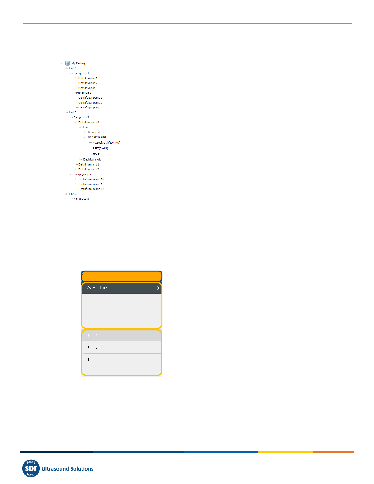
16. Tree navigation and data storage in Free Mode
The example hereafter uses the following UAS tree structure:
Unit 1 ❺, Unit 2 ❻and Unit 3 ❼are the children of My
Factory ❽. They have the same level in the tree structure. In the
same way, Centrifugal pump 1, 2 and 3 are children of Pump
group and have the same level. Fan group is the parent of Belt
Drive fan 1, 2 and 3…
Belt Drive fan ❶should be considered as machinery. Fan ❷
and Electrical motor are the components of one machinery.
Drive end ❸and Non-Drive end are the measurement locations.
A measurement location is namely the contact sensor place or
the target for non-contact probes. For instance, the bearing
housing or pillow block is measurement locations when using the
accelerometer or the RS2T.
Acc100 [10-1k] ❹as a measurement type.
A measurement type is the combination of a technology (Acc
means vibration accelerometer), a sensor sensitivity (100 means
100 mV/g) and a specific setting ([10-1k] means a measurement
bandwidth between 10 Hz and 1 kHz).
Figure 20: example of tree structure
The SDT340 features an intuitive and quick way to navigate, going up and going down, by hierarchical
levels of the tree structure.
The list of the nodes of the selected level is placed in the upper section. Use the Right key to go up the
higher level, the parent (if exists). Its name is indicated with its path in the top section. Select the
desired node of the upper section with the Up and Down keys. Then using the right key, go down the
lower level, the children. The corresponding nodes are shown in the lower section.
❶Top section
❷Upper section
❸Lower section
Figure 21: Top, upper and lower sections
This method, common to the Free Mode, the Tree Mode and the Survey Mode, makes it easy to
navigate in between measurement types in large tree structure.
The way of proceeding is detailed with an example based on the following tree structure.
❶
❷
❸
❹
❺
❻
❼
❽
❶
❷
❸
Version 01 2018-12 © SDT International. All rights reserved
MAN.340.EN--01--SDT340-user-manual-Eng.docx
19/30
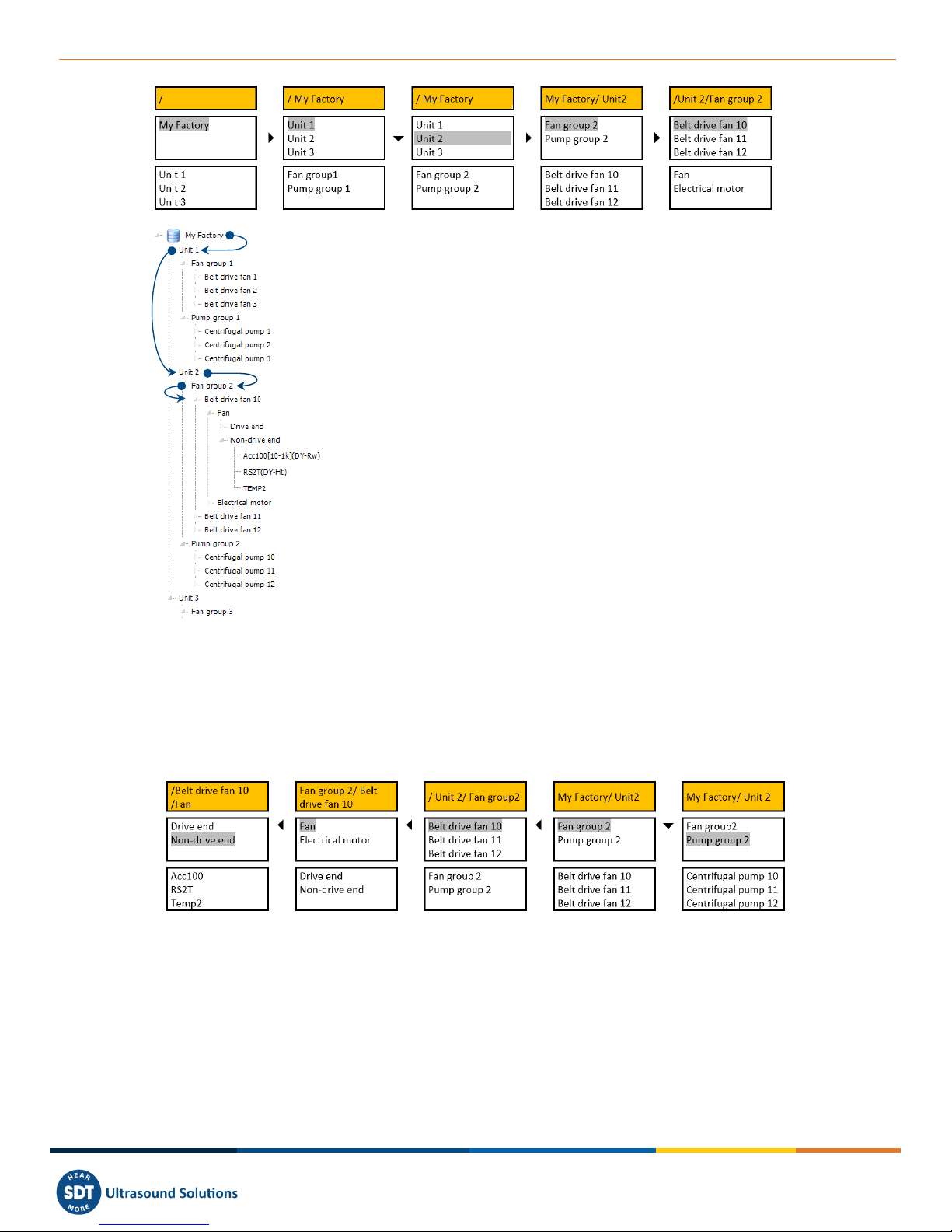
After freezing the measurement and pressing Enter, My Factory is
selected in the upper section ❶. The lower section ❷contains the
lower-level nodes of My Factory, Unit 1, Unit 2 and Unit 3.
Pressing the Right key ❸, now the upper section contains Unit 1,
Unit 2 and Unit 3. The top section ❹contains the higher-level node
of Unit 1, Unit 2 and Unit 3. The lower section contains the lower-
level nodes of Unit 1, Fan group 1 and Pump group 1.
Pressing the Down key ❺, Unit 2 is now selected. The lower section
contains its lower-level nodes: Fan group 2 and Pump group 2.
Pressing the Right key, Fan group 2 is selected. The lower section
contains Belt Drive 10, Belt Drive 11 and Belt Drive 12.
Pressing the Right key, Belt Drive fan 10 is selected in the upper
section. The lower section contains Fan and Electrical motor.
When reaching a measurement location node, press Enter.
Figure 22: Tree structure navigation (1)
You don’t need to go down to the measurement type level. You can directly store data from the
measurement location level by pressing Enter. In Free Mode, if the measurement type doesn’t exist, it
will be created automatically.
Naturally, you could also navigate from lower-level to higher-level nodes, as demonstrate in the
following example.
Figure 23: Tree structure navigation (2)
Non-Drive end is selected. Pressing Left, the upper section contains the nodes having an upper-level
than Non-Drive end: Fan and Electrical motor. Another Left press, the upper section is refreshed
showing Belt Drive fan 10, Belt drive fan 11, and Belt drive fan 12. After the next Left press, Fan 2 and
Pump group 2 appear in the upper section. Pressing the Down key will select Pump group 2.
❶
❷
❸
❹
❺
❸
Version 01 2018-12 © SDT International. All rights reserved
MAN.340.EN--01--SDT340-user-manual-Eng.docx
20/30
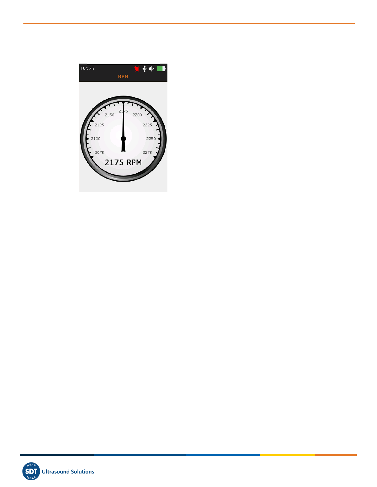
17. Rotational speed
❶Running RPM
❷Laser Icon activated
Figure 25: Rotational speed
From the Home screen, select the RPM icon and press Enter. The running RPM screen is displayed
(Figure 25). The value ❶is refreshed twice per seconds. Press the Laser hold-on key to activate it. The
laser icon ❷indicates when the laser is on.
Press Enter to freeze the temperature measurement and once more to record the measurement.
Select the desired memory location and confirm your choice with Enter.
❶
❷
Version 01 2018-12 © SDT International. All rights reserved
Other manuals for SDT340
1
Table of contents
Other SDT International Measuring Instrument manuals


