SDT International SDT170 User manual

MAN.170.EN--04--SDT170-user-manual-Eng.docx
1/141
SDT170
SDT International sa-nv • Bd de l’Humanité 415 • B-1190 Brussels (Belgium) • Tel: +32(0)2 332 32 25 • [email protected] • www.sdtultrasound.com

MAN.170.EN--04--SDT170-user-manual-Eng.docx
2/141
Copyright 2009 by SDT International n.v. s.a.
Seventh edition.
All rights reserved: No one is permitted to reproduce or duplicate, in any form, the
whole or part of this document without the written permission of SDT International
n.v. s.a.
The information herein is believed to be accurate to the best of our knowledge.
Due to continued research and development, specifications of this product can
change without prior notice.
SDT International n.v. s.a.
Bd. de l’Humanité 415,
B –1190 Brussels (BELGIUM)
Tel: ++32.2.332.32.25
Fax: ++32.2.376.27.07
web page: http://www.sdt.be
V579

3
Table of contents
1. The user’s manual..........................................................................4
2. The package....................................................................................5
3. Recharging the battery pack.........................................................6
4. Using the SDT 170 S and S+ .........................................................8
5. Using the SDT 170 M and M+......................................................12
6. Using the SDT 170 MD.................................................................20
7. Presentation..................................................................................27
8. The Main menu (all versions)......................................................41
9. The Select Route menu (MD only)..............................................45
10. The View Data menu (M, M+ and MD).........................................47
11. The Erase Data menu (M, M+ and MD).......................................50
12. The Settings menu (all versions)................................................52
13. The System Info menu.................................................................63
14. Technical considerations............................................................67
15. Recharging the battery pack.......................................................70
16. Internal ultrasonic sensor ...........................................................76
17. External ultrasonic sensors........................................................78
18. Adaptators for ultrasonic sensors .............................................92
19. Ultrasonic transmitters................................................................94
20. External non ultrasonic sensors ................................................98
21. Cables..........................................................................................112
22. Technical specifications............................................................118
23. Specificities of the SDT 170 M, M+ and MD...............................122
24. Declaration of conformity in the European Union..................127
25. Destruction and recycling of waste equipment......................128
26. Warranty and responsibility limits ...........................................129
27. Index............................................................................................130
28. Contents......................................................................................136

MAN.170.EN--04--SDT170-user-manual-Eng.docx
4/141
1. The user’s manual
This User’s manual must be red carefully and completely prior to anyone using the
equipment.
The User’s manual is designed as an educational guide and reference tool for
anyone who wishes to use the SDT 170 equipment for its intended purpose.
SDT produces this manual with the sole purpose of supplying simple and accurate
information to the user. SDT shall not be held responsible for any miss-
interpretation of this manual. Despite our efforts to provide an accurate manual, it
may contain technical errors beyond our control. If in doubt, contact your local
SDT distributor for clarification.
While every effort was made to present a true and accurate text, modifications
and/or improvements to the product described herein can be made at any time
without corresponding changes being made to the manual.
This User’s manual and its contents remain the inalienable property of SDT.
MAN.170.EN--04--SDT170-user-manual-Eng.docx
5/141
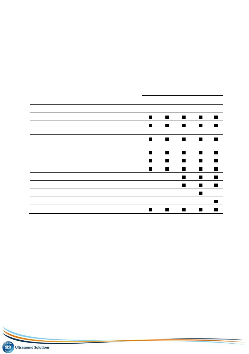
2. The package
According to the type delivered, the package contains the following elements:
Model
S
S+
M
M+
MD
Storage case and foam
Unit with battery, rubber protection and user
manual
Precision accessories (threaded tip, rubber
precision cone and 2 plastic extensions)
Headphones 130 dB, noise isolating
Battery charger
Shoulder strap
Contact probe and needle
Center punch
MPlus software (1)
DataManager software (2)
Cable RS232
(1) Data transfer from the unit to the PC. Delivered on a 3 ½’’ floppy disk.
(2) Delivered on Cd-rom with user manual.

6
3. Recharging the battery pack
The battery pack must be charged before its first use.
The charger must be unplugged from the mains before recharging a
new battery, in order to reset the internal timer.
3.1 RECHARGING THE BATTERY PACK IN THE UNIT
The connection of the charger to the unit. 052
1. Connect the charger connector to the unit and plug the charger into the
mains power socket.
The charging will be done in about 5 to 6 hours when the unit is switched off,
or 12 to 14 hours when the equipment is used.
2. The end of charging is done when the charger light is off.
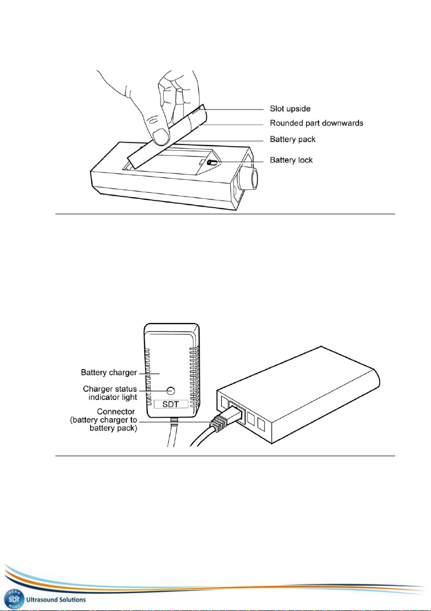
3.2 RECHARGING THE BATTERY PACK OUT OF THE UNIT
1. Remove the battery pack by turning the equipment.
Maintain the battery lock towards the front of the equipment. Place your hand
under the battery pack and gently tap the unit against your hand. The battery
pack will release easily using this method.
Recharging the battery pack
MAN.170.EN--04--SDT170-user-manual-Eng.docx
7/141
Removing of the battery. 053
2. Plug the connector on the end of the battery charger into the connector
on the battery pack.
3. Plug the battery charger in the mains socket.
The charging cycle will take about 5 to 6 hours to be completed. The end of
charging is done when the charger light is off
4. Once charging over, replace the charged battery pack in the unit, like
previously indicated.
Connection of the battery charger onto the battery pack. 054
8
4. Using the SDT 170 S and S+
The chapter allows a quick use of the SDT 170 S and S+. It is nevertheless highly
recommended to read carefully the whole manual before using the equipment.
This chapter can therefore be considered has a quick reference guide.
4.1 RECHARGING ON THE EQUIPMENT
Refer to the chapter 3.
4.2 SWITCHING ON THE EQUIPMENT
1. Remove the sensor protective cap and press the key to switch on.
The build in automated self-test is started and takes about 2 seconds to
finish.
2. The unit is ready to use if no problem or fault is detected during this
build in self-test.
The message Battery charge too low flashes on the screen when the
battery pack’s charge is to low. Recharge the battery; see previous chapter.
4.3 THE SCREEN AFTER POWER ON
The SDT 170 S+ displays a digital measurement, while the SDT 170 S only
displays a bargraph.
SDT 170 S
The display shows the information as indicated in the following picture.
The measurement screen of the SDT 170 S displays a bargraph. 081
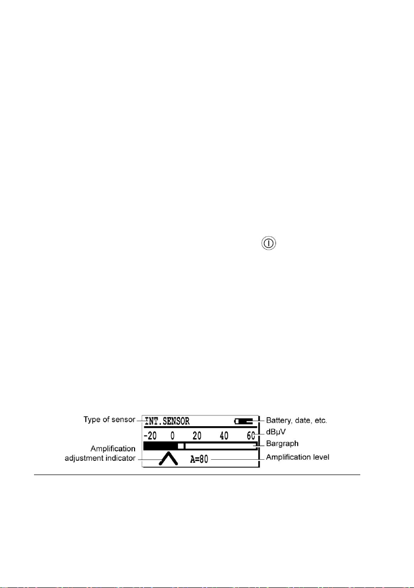
SDT 170 S+
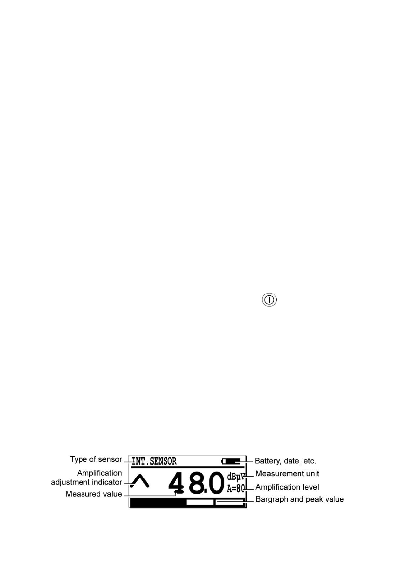
The display shows the following information.

4. Using the SDT 170 S and S+
MAN.170.EN--04--SDT170-user-manual-Eng.docx
9/141
The measurement screen of the SDT 170 S+ displays a digital measurement. 083
4.4 CONNECTING THE OPTIONAL EXTERNAL SENSOR
If the measure requires an external optional ultrasonic sensor, connect it to the
corresponding connector.
The external sensor connector. 034
4.5 SELECTION OF THE WORKING LANGUAGE
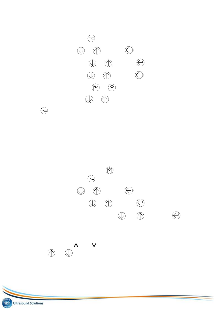
1. Select the main menu with .
2. Settings... selected, push .
3. Select Language… with or and push .
4. Select the working language with or and push .
5. Push to go back to the main menu.
4.6 SELECTION OF THE FREQUENCY BAND
In this mode, the SDT 170 can not be used to measure or to store
measurements. It can only be used to hear the ultrasounds signals.
If the standard frequency band (38.4 kHz) if sufficient, go to point 4.7.
If not, select the new frequency band, as follows:
1. Select the main menu with .
4. Using the SDT 170 S and S+
MAN.170.EN--04--SDT170-user-manual-Eng.docx
10/141
2. Settings... being already selected, push .
3. Select Sensor options with or and push .
4. Discov.fr.band being already selected, push .
5. Set the frequency band displayed on the screen with or .
6. Push to go back to the main menu.
4.7 SELECTION OF THE AMPLIFICATION LEVEL
1. Look at the arrows ( and ) to optimize the amplification level (A).
Use the or buttons to modify the value Aat the bottom of the
screen.
- When the SDT170 receives ultrasonic sounds from a source, set the
amplification level to have no arrow on the screen.
- When no ultrasonic signal is present, set the amplification to A = 80.
Note: it is advisable to begin the measurement with the maximal amplification
(A = 80).

4. Using the SDT 170 S and S+
MAN.170.EN--04--SDT170-user-manual-Eng.docx
11/141
4.8 TAKING A MEASUREMENT
SDT 170 S
1. Remove the sensor protective cap.
2. Direct the internal sensor towards the noise source using or not an
adaptator (precision accessories).
The screen indicates the measure.
The measurement screen of the SDT 170 S displays a bargraph. 082
SDT 170 S+
1. Remove the sensor protective cap.
2. Direct the internal sensor towards the noise source using or not an
adaptator (precision accessories).
The screen indicates the measure.
The measurement screen of the SDT 170 S+ displays a digital measurement. 084
4.9 SWITCHING OFF
1. Briefly press the key.
Note: the unit will also automatically switch off after a pre-programmed period.
2. Fix the sensor protective cap.
12
5. Using the SDT 170 M and M+
The chapter allows a quick use of the SDT 170 M and SDT 170 M+. It is
nevertheless highly recommended to read carefully the whole manual before
using the equipment. This chapter can therefore be considered has a quick
reference guide.
Unlike the M version, the SDT 170 M+ can be connected to a PC on which the
transfer software MPlus will be fist installed. One the data memorized bye the
SDT 170 M+ transferred on the PC, these later can be viewed of processed by a
specific software.
5.1 RECHARGING ON THE EQUIPMENT
Refer to the chapter 3.
5.2 SWITCHING ON THE EQUIPMENT
1. Remove the sensor protective cap and press the key to switch on.
The build in automated self-test is started and takes about two seconds to
finish.
2. The unit is ready to use if no problem or fault is detected during this
build in self-test.
The message Battery charge too low flashes on the screen when the
battery pack’s charge is to low. Recharge the battery; see chapter 3.
5.3 THE SCREEN AFTER POWER ON
If the SDT170 M or SDT 170 M+ works with the:
Continuous function, the screen is as shown below (see paragraph 5.7).
Max value function, the screen shown any numeric value (see paragraph 5.7).
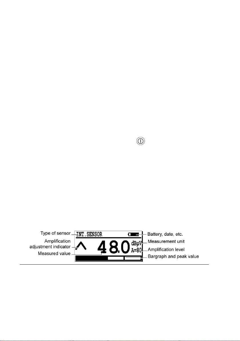
The measurement screen. 083

5. Using the SDT 170 M and M+
MAN.170.EN--04--SDT170-user-manual-Eng.docx
13/141
5.4 CONNECTING THE OPTIONAL EXTERNAL SENSOR
If the measure requires an external optional ultrasonic or non ultrasonic sensor,
connect it to the corresponding connector.
The external sensor connector. 034
5.5 SELECTION OF THE WORKING LANGUAGE
1. Select the main menu with .
2. Settings... selected, push .
3. Select Language… with or and push .
4. Select the working language with or and push .
5. Push to go back to the main menu.
5.6 SELECTION OF THE FREQUENCY BAND
In this mode, the SDT 170 can not be used to measure or to store
measurements. It can only be used to hear the ultrasounds signals.
If the standard frequency band (38.4 kHz) is correct, go to point 5.7. If not, select
the new frequency band, as follows.
5. Using the SDT 170 M and M+
MAN.170.EN--04--SDT170-user-manual-Eng.docx
14/141
1. Select the main menu with .
2. Select Settings... with or and push .
3. Select Sensor options with or and push .
4. Select Discov.fr.band with or and push .
5. Set the frequency band with or .
6. Set the amplification with or .
7. Push to close this screen.
5.7 SELECTING THE CONTINUOUS/MAX VALUE
FUNCTION
Use the function:
Continuous when the average value is to be measured. The screen will
always display the value.
Max value function when the peak value is to be measured. The screen will
display the value only when pressing .
1. Select the main menu with .
2. Select Settings... with or and push .
3. Select Sensor options with or and push .
4. Select Continuous or Max value with or and push to
validate.
5.8 SELECTION OF THE AMPLIFICATION LEVEL
1. Look at the arrows ( and ) to optimize the amplification level (A).
Use the or buttons to modify the value Aat the bottom of the
screen.
- When the SDT 170 receives ultrasonic sounds from a source, set the
amplification level to have no arrow on the screen.
- When no ultrasonic signal is present, set the amplification to A = 80.
5. Using the SDT 170 M and M+
MAN.170.EN--04--SDT170-user-manual-Eng.docx
15/141
Note: it is advisable to begin the measurement with the maximal amplification
(A = 80).
5.9 TAKING A MEASUREMENT
When using the continuous function
Use this function when the average value is to be measured.
1. Point the sensor to the point to be controlled.
2. Read the signal level on the display.
The signal changes continuously. Measurement is to be performed while
listening at headphone signals.
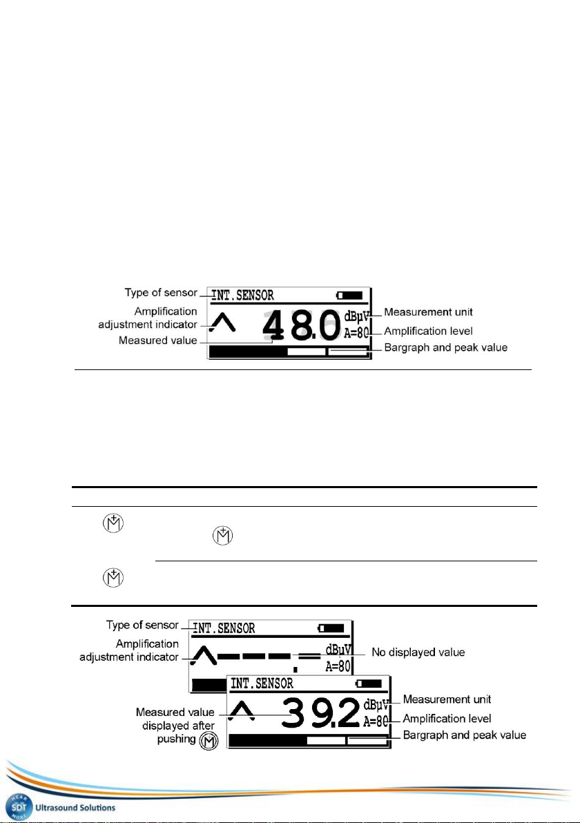
The measurement screen when using the continuous function. 084
When using the Max value function
Use this function when the maximal value is to be measured.
1. Direct the sensor to the point to be controlled.
2. To visualize the signal level:
Press
Result
The maximum (peak value) is displayed for as long as the key is pressed.
When the key is released, the SDT 170 stops measuring. The display
shows the highest value recorded while the key was pressed.
To make a new measurement and erase the previous maximum value, just
press this again. If needed, store the measured value. Refer to next
paragraph.

5. Using the SDT 170 M and M+
MAN.170.EN--04--SDT170-user-manual-Eng.docx
16/141
The measurement screen when using the maximal function. 094
5.10STORING A MEASURED VALUE
Once the measured value is displayed on the screen and to store it in the data
logger memory, proceed as follows:
1. Push to display the memory location menu.
2. With or , choose the memory location (for example 2/999) for
data storage.
3. Push to display the value to be stored in the selected memory
location. The type of sensor, date, time and value are also displayed.
4. Push to store the data which are now stored in memory.
The measurement screen is automatically displayed ready for a new
measurement.
5.11VIEWING A PREVIOUS STORED VALUE
To view a stored value in the data logger memory, proceed as follows:
1. Select the main menu with .
2. With or , choose View data and push .
3. With or , choose the memory location (for example 2/999) to be
displayed and push .
If exist, the recorded reading(s) is (are) displayed.
4. With or , choose one of these readings and push .
The data regarding the selected reading is displayed.
5. Push until return to the measurement screen.
5.12ERASING A STORED VALUE
To erase a stored value in the data logger memory, proceed as follows:
1. From the main menu push .

5. Using the SDT 170 M and M+
MAN.170.EN--04--SDT170-user-manual-Eng.docx
17/141
2. With or , choose Erase data and push .
3. With or , choose the memory location (for example 2/999) to be
erased and push .
If exist, the previous recorded reading(s) is (are) displayed.
4. With or , choose one of these readings and push .
The date regarding the selected reading is displayed.
5. Depress to erase the displayed data.
Note: push to abort the procedure without erasing and return to the
previous screen.
6. Push until return to the measurement screen.
5.13SWITCHING OFF
1. Briefly press the key.
Note: the unit will also automatically switch off after a pre-programmed period.
2. Fix the sensor protective cap.

5. Using the SDT 170 M and M+
MAN.170.EN--04--SDT170-user-manual-Eng.docx
18/141
5.14 TRANSFERT OF DATA FROM THE SDT 170 M+ TO
THE PC
Installing the software on the PC
1. Insert the floppy disk in the disk drive of the PC.
2. Move the MPlus.exe file in a folder of the PC or on the Windows® desk.
Transferring the data to the PC
Proceed as follows:
Step
Displayed screen
Button
Action
1
254
Connect the delivered cable on the SDT
170 M+ and the serial input of the PC.
2
Switch on the SDT 170 M+.
3
On the PC, double click on the icon to
launch the MPlus.exe application.
4
Click the button Browse.
5
a) Select the folder in which the data
coming from the SDT 170 M+ will be
saved.
b) In the field File name, enter the name
of the file (txt file) under which the data
coming from the SDT 170 M+ will be
saved.
c) Click Open.
6
Click the button COM Port Setup.
a b c

5. Using the SDT 170 M and M+
MAN.170.EN--04--SDT170-user-manual-Eng.docx
19/141
7
Select the communication port on which
the PC-SDT 170 M+ is connected to and
click OK.
8
Click on the Get data button to launch
the transfer of the memorized data by the
SDT 170 M+ towards the PC.
The message No response of
SDT170 is displayed when a fault occurs
during the transfer due to at least one of
the following causes :
- SDT 170 M+ is off.
- Battery flat or discharged.
- Bad connection of the link cable or
defect.
- Bad selection of the Com port.
9
If necessary, click Erase to erase all data
previously stored in the SDT 170 M+
memory.
10
Once the transfer achieved, click on the
Close button to close the MPLus
application.
11
Switch of the SDT 170 M+.
20
6. Using the SDT 170 MD
The chapter allows a quick use of the SDT 170 MD. It is nevertheless highly
recommended to read carefully the whole manual before using the equipment.
This chapter can therefore be considered has a quick reference guide.
6.1 RECHARGING ON THE EQUIPMENT
Refer to the chapter 3.
6.2 SWITCHING ON THE EQUIPMENT
1. Remove the sensor protective cap and the key to switch on.
The build in automated self-test is started and takes about two seconds to
finish.
2. The unit is ready to use if no problem or fault is detected during this
build in self-test.
The message Battery charge too low flashes on the screen when the
battery pack’s charge is to low. Recharge the battery; see chapter 3.
6.3 THE SCREEN AFTER POWER ON
If the SDT170 works with the:
Continuous function, the screen is as shown below (see paragraph 6.6).
Max val function, the screen shown any numeric value (see paragraph 6.6).
The measurement screen. 083
Table of contents
Other SDT International Measuring Instrument manuals


 instruction manual")


