BEKA BA527C User manual

Issue: 3
5th March 2009
BA527C & BA528C
loop-powered
4½ digit panel
mounting indicators
Issue 3

2
1. Description
2. Operation
2.1 Controls
3. Application
3.1 Transmitter loops
3.2 Remote indication
4. Installation
4.1 Location
4.2 Installation procedure
4.3 EMC
5. Programming and Calibration
5.1 Summary of programmable functions
5.2 Root extractor
5.3 Resolution
5.4 Position of decimal point
5.5 Calibration using an external current
source.
5.6 Calibration using internal references
5.7 Conditioning sub-menu
5.7.1 AC rejection
5.7.2 Calibration of internal
references.
5.8 Function of the Ppush-button
5.9 Security code
5.10 Over and under-range
6. Calibration Example
6.1 Using an external current source
6.2 Using the internal calibrator
7. Maintenance
7.1 Fault finding during commissioning
7.2 Fault finding after commissioning
7.3 Servicing
7.4 Routine maintenance
7.5 Guarantee
7.6 Customer comments
8. Accessories
8.1 Scale card
8.2 Tag strip
8.3 Alarms
8.3.1 Solid state output
8.3.2 Programming and adjustment
8.3.3 Alarm enable
8.3.4 Setpoint adjustment
8.3.5 Alarm function
8.3.6 Alarm output status
8.3.7 Hysteresis
8.3.8 Alarm delay
8.3.9 Alarm silence time
8.3.10 Access setpoint
8.3.11 Adjusting alarm setpoints from
display mode.
8.4 Lineariser
8.4.1 Calibration using an external
source.
8.4.2 Calibration using internal
references.
8.5 Tare function
8.6 Display backlight
CONTENTS
The BA527C and BA528C indicators are CE marked to
show compliance with the European EMC Directive 2004/108/EC

3
1. Description
The BA527C and BA528C are 4½ digit loop
powered digital indicators which display the current
flowing in a 4/20mA loop in engineering units. Both
instruments introduce less than a 1.1V drop which
allows them to be installed into almost any 4/20mA
current loop. No additional power supply or battery
is required.
The two indicators are electrically similar, but have
different size displays and enclosures.
Model Display height Bezel size
BA527C 10mm 96 x 48mm
BA528C 20mm 144 x 72mm
Both are second generation instruments, which
although providing additional functions, remain
compatible with the original BA527 and BA528.
The main application of the BA527C and BA528C
is to display a measured variable or control signal
in a process area. The zero and span of the
display are independently adjustable so that the
indicators can be calibrated to display any variable
represented by the 4/20mA current, e.g.
temperature, flow, pressure or level.
2. Operation
Fig 1 shows a simplified block diagram of both
models. The 4/20mA input current flows through
resistor R1 and forward biased diode D1. The
voltage developed across D1, which is relatively
constant, is multiplied by a switch mode power
supply and used to power the instrument. The
voltage developed across R1, which is proportional
to the 4/20mA input current, provides the input
signal for the analogue to digital converter.
Fig 1 Simplified block diagram
Each time a 4/20mA current is applied to the
instrument, initialisation is performed. After a short
delay the following display sequence occurs:
-1.8.8.8.8 Display test in which all
segments of the display
are activated for 0.5
seconds.
Blank display For 0.5 seconds.
Decimal points For 3 seconds.
cycled.
Input current Using calibration
display in information stored in
engineering instrument memory.
units.
2.1 Controls
The BA527C and BA528C are controlled and
calibrated via four push-button switches. In the
display mode these switches have the following
functions:
PWhile this button is pushed the indicator
will display the input current in mA, or
as a percentage of the instrument span
depending upon how the indicator has
been programmed. When the button is
released the normal display in
engineering units will return. The
function of this push-button is modified
when alarms or a tare function are fitted
to the indicator.
Down While this button is pushed the indicator
will display the number which the
indicator has been calibrated to display
with a 4mA input. When released the
normal display in engineering units will
return.
Up While this button is pushed the indicator
will display the number which the
indicator has been calibrated to display
with a 20mA input. When released the
normal display in engineering units will
return.
ENo function in the display mode.

4
3. Application
3.1 Transmitter loops
BA527C and BA528C indicators may be
connected in series with any 4/20mA current loop
providing the loop can tolerate the additional 1.1V
required to operate the indicator. Fig 2 illustrates a
typical application in which a BA527C or BA528C
indicator is connected in series with a 2-wire
transmitter.
Fig 2 BA527C or BA528C in a transmitter loop
The sum of the maximum voltage drop of all the
components must be less than the minimum power
supply voltage.
Minimum operating voltage of 2-wire Tx 10.0
Maximum voltage drop caused by controller 5.0
Maximum voltage droop caused by indicator 1.1
Maximum voltage drop caused by cables 0.4
______
16.5V
Therefore at 20mA the power supply in this
example must have an output greater than 16.5V
3.2 Remote indication
BA527C and BA528C indicators may be driven
from any 4/20mA signal to provide a remote
indication. Fig 3 shows a typical application in
which the output from a gas analyser drives a
BA527C or BA528C indicator. Again it is necessary
to ensure that the voltage capability of the 4/20mA
output is greater than the sum of the voltage drops
caused by the indicator and the cable resistance
Fig 3 Remote indication
4. Installation
4.1 Location
BA527C and BA528C indicators are housed in
robust aluminium enclosures with polyester front
panels and Noryl bezels. The fronts of both
instruments have IP65 protection, and a gasket
seals the joint between the instrument enclosure
and the panel. The indicators may be installed in
any panel providing the environmental limits shown
in the specification are not exceeded.
Figs 4A and 4B show the overall dimensions of
each instrument and the required panel cut-out
dimensions. To achieve an IP65 seal between the
instrument enclosure and the instrument panel the
smaller tolerance aperture must be used, and the
BA528C must be secured with four mounting clips.

5
Fig 4A BA527C dimensions
4.2 Installation Procedure
a. Insert the indicator into the instrument panel
from the front of the panel.
b. Fix two panel mounting clips to opposite sides
of the instrument and tighten until the indicator
is secure as shown in Fig 5. Four clips are
required to achieve an IP65 between a
BA528C and the instrument panel.
Fig 4B BA528C dimensions
c. Connect the panel wiring to the rear terminal
block(s) as shown in Figs 4A and 4B. To
simplify installation, the terminals are
removable so that the panel wiring can be
completed before the instrument is installed.

6
Fig 5 Fitting panel mounting clips
4.3 EMC
The BA527C and BA528C comply with the
requirements of the European EMC Directive
2004/108/EC. For specified immunity all wiring
should be in screened twisted pairs. The indicator
enclosure may be earthed locally by putting a tag
under one of the rear panel fixing screws. EMC
performance is shown in the instrument
specification, and copies of the test report are
available from BEKA associates.
5. Programming and Calibration
The BA527C and BA528C are programmed and
calibrated via four front panel push-buttons. All the
functions are contained in an easy to use menu
which is shown diagramatically in Fig 6. Each
function is summarised in section 5.1 which
includes references to more detailed information.
Although this simple menu driven system enables
most adjustments to be made without repeated
reference to this manual, we recommend that at
least the summary of programmable functions in
section 5.1 is read before starting recalibration.
When the indicator is fitted with alarms,
linearisation or a tare function, additional functions
are added to the menu. These accessories are
described in section 8 of this manual.
Throughout this manual push-buttons are shown in
italics e.g. Por Up push-button, and legends
displayed by the indicator are shown within
inverted commas e.g. 'CAL' and ' ALr2'.
Access to the programme menu is obtained by
operating the Pand Epush-buttons
simultaneously. If the instrument is not protected
by a security code the first parameter 'root' will be
displayed. If a security code other than the default
code 0000 has already been entered, the indicator
will display 'COdE'. Press Pto clear this prompt
and enter the security code for the instrument
using the Up, Down and Ppush-buttons. If the
correct code has been entered pressing Ewill
cause the first parameter 'root' to be displayed. If
an incorrect code is entered the indicator will return
to the display mode.
Once within the menu the required parameter can
be reached by scrolling through the main menu
using the Up and Down push-buttons as shown in
Fig 6. When returning to the display mode
following recalibration or changes to any
parameters, the indicator will display circulating
decimal points for a few seconds while the new
information is stored in permanent memory.
All new BA527C and BA528C indicators are
supplied calibrated as requested at the time of
ordering. If calibration is not requested, the
indicator will be set to display 0.00 with 4mA input,
and 100.00 with 20mA input, but can easily be re-
calibrated on-site.

7
5.1 Summary of programmable functions
This section summarises each of the main
programmable functions and includes cross
references to more detailed information. Fig 6
illustrates the location of each function within the
menu.
Display Description of function
'root' Square root extractor
Turns the square root extractor for
linearising the output from differential
flowmeters on or off. This function is
omitted when a lineariser is installed.
See section 5.2
'rESn' Display resolution
Selects the resolution of the least
significant display digit. May be set to
1, 2, 5 or 10 digits.
See section 5.3
'd.P.' Decimal point
Positions the dummy decimal point
between any of the digits or turns it
off.
See section 5.4
'CAL' Calibration of display using the
external current source.
Enables the zero and span of the
indicator to be adjusted using an
external current source such as a
calibrator. Also enables a complete
loop to be calibrated from primary
element to the indicator display.
When used with an accurate traceable
current source this is the preferred
method of calibration.
See section 5.5
'SEt' Calibration of display using internal
references.
Enables the zero and span of the
indicator to be adjusted without the
need for an accurate input current or
disconnection from the 4/20mA loop.
See section 5.6
Display Description of function
'Cond' Indicator conditioning
This function provides access to a
sub-menu enabling the internal
references to be calibrated, and the
mains (line) frequency rejection to be
selected. Because these parameters
will alter the indicator display, they are
contained in a sub-menu to prevent
inadvertent adjustment.
See section 5.7
'FrE' Frequency rejection
Defines the mains (line) frequency at
which the indicator has maximum ac
rejection. 50 or 60Hz may be
selected. This function must be set
before the instrument is calibrated as
it affects the indicator display.
See section 5.7.1
'rEF' Calibration of internal references
The indicator contains two references
representing 4 and 20mA. These
internal references are used when the
indicator display is calibrated without
an external current calibrator, and
when the input current is displayed in
milliamps. See the SEt and C—P
functions. If either of these functions is
to be used, the internal references
should be periodically calibrated.
See section 5.7.2
'C - - P' Function of P push-button
The Ppush-button may be
programmed to display the input
current in milliamps or the input
current as a percentage of the
displayed span.
See section 5.8
'COdE' Security code
Defines a four digit numeric code
which must be entered to gain access
to programmable functions. Default
code 0000 disables the security
function and allows unrestricted
access to all programmable functions.
See section 5.9

8

9
5.2 Root extractor: root
This function is primarily intended for use with
differential flowmeters which have a square law
4/20mA output. To activate the square root
extractor select 'root' from the menu and press P
which will reveal if the function is 'On' or 'OFF'. If
the function is set as required, press Eto return to
the menu, or press the Up or Down button to
change the setting, followed by the Ebutton to
return to the main menu.
For reference, the following table shows the output
current from a non-linearised differential flowmeter.
% of full flow Current output mA
2.5 4.01
10.0 4.16
25.0 5.00
50.0 8.00
75.0 13.00
100.0 20.00
5.3 Resolution: rESn
This function defines the resolution of the least
significant display digit. Decreasing the display
resolution can improve the readability of a noisy
signal. Select 'rESn' from the menu and press P
which will reveal the current display resolution. To
change the resolution press the Up or Down button
to select 1, 2, 5 or 10 digits, followed by the E
button to return to the menu.
5.4 Position of the decimal point: d.P.
A dummy decimal point can be positioned between
any of the digits or may be absent. To position the
decimal point select 'd.P.' from the menu and press
P. The decimal point can then be moved or turned
off by pressing the Up or Down push-button,
followed by Eto return to the menu.
5.5 Calibration using an external
current source: CAL
This function enables the zero and span of the
indicator to be adjusted using an external
calibrated current source. When used with an
accurate traceable current source this is the
preferred method of calibration.
To calibrate the indicator select 'CAL' from the
main menu and press P. The indicator will display
'ZErO' which is a request for a 4mA input current.
Adjust the external current calibrator to 4.000mA
and again press Pwhich will reveal the current
zero display. Each digit of the indicator display can
be changed by pressing the Up or Down buttons.
When the first digit is correct pressing Pwill
transfer control to the next digit. When all the digits
have been adjusted, press Eto enter the new zero.
The indicator will display 'Ent' for a few seconds
while the information is being stored in memory,
and will then return to the 'ZErO' prompt.
To adjust the display at 20mA, press the Up button
which will cause the indicator to display 'SPAn'.
Adjust the external current calibrator to 20.000mA
and again press Pwhich will reveal the existing full
scale display. Each digit of the indicator display
can be changed by pressing the Up or Down
buttons. When the first digit is correct pressing P
will transfer control to the next digit. When all the
digits have been adjusted press Eto enter the new
span. The indicator will display 'Ent' for a few
seconds while the information is being stored in
memory, and will then return to the 'SPAn' prompt.
Finally press Eagain to return to the main menu.
This function may also be used when calibrating a
complete loop from primary element to indicator
display e.g. when the indicator is displaying the
output from a resistance thermometer to current
converter.
5.6 Calibration using internal references: SEt
This function enables the zero and span of the
indicator to be adjusted without the need for an
accurate external current source, or for
disconnection from the 4/20mA loop.
The accuracy of this method depends upon the
accuracy of the internal references which should
be regularly calibrated as described in section
5.7.2
To calibrate the indicator select 'SEt' from the main
menu and press P. The indicator will display 'ZErO'
, pressing Pagain will reveal the current display at
4mA. Each digit of the indicator display can be
changed by pressing the Up or Down buttons.
When the first digit is correct pressing Pwill
transfer control to the next digit. When the least
significant digit has been adjusted, press Eto
return to the 'ZErO' prompt which completes the
adjustment.
To adjust the display at 20mA, press the Up button
which will cause the indicator to display 'SPAn'.
pressing Pagain will reveal the indicator display.
Each digit can be changed by pressing the Up or
Down buttons. When the first digit is correct
pressing Pwill transfer control to the next digit.
When the least significant digit has been adjusted
press Eto return to the 'SPAn' prompt followed by
Eto return to the main menu.

10
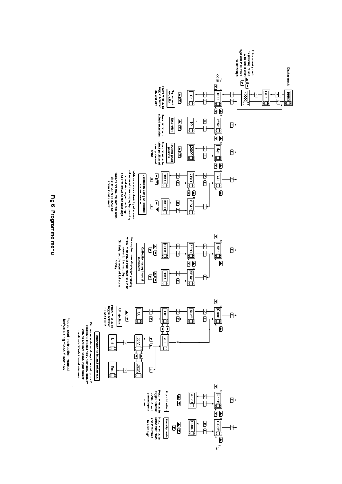
5.7 Conditioning sub-menu: Cond
This sub-menu allows the mains (line) frequency at
which the indicator has maximum ac rejection to be
selected and the two internal references to be
calibrated. These functions are contained in a sub-
menu to minimise the possibility of inadvertent
adjustment. To gain access to the sub-menu select
'Cond' from the main menu and press P. The
indicator will display 'SurE' to warn that changing
the parameters in the sub-menu will change the
indicator display. Pressing Pagain will give access
to the sub-menu, or pressing Ewill return the
indicator to the main menu.
5.7.1 AC rejection: FrE
Caution
If the mains filter frequency is
changed, the indicator display and
internal references (if used) must
be recalibrated.
To provide maximum low frequency rejection the
internal digital filter may be set to operate at 50 or
60Hz to correspond with the local mains (line)
frequency. To change the frequency select 'FrE'
from the Cond sub-menu and press Pwhich will
reveal the current setting. The setting can be
changed by pressing the Up or Down buttons
followed by the Ebutton to return to the sub-menu.
5.7.2 Calibration of internal references: rEF
The indicator contains two references representing
4 and 20mA. These references are used in the
'SEt' function which enables the indicator display to
be calibrated without an external current calibrator.
They are also used in the 'C--P' function when the
Ppush-button is programmed to display the input
current in the display mode. If neither of these
functions is to be used, it is not necessary to
calibrate the internal references.
To calibrate the references select 'rEF' from the
sub-menu and press Pwhich will result in a
'0.004A' prompt being displayed. Adjust the
external current calibrator to 4.000mA and again
press P. The indicator will display 'Ent' when the
4mA reference has been updated and will then
return to the '.004A' prompt.
To re-calibrate the 20mA internal reference, press
the Up button which will cause the indicator to
display '.020A'. Adjust the external current
calibrator to 20.000mA and again press P. The
indicator will display 'Ent' when the 20mA
reference has been updated and will then return to
the '.020A' prompt. Two operations of the Ebutton
will return the indicator to the main menu.
The accuracy of the internal references, and hence
the display accuracy, will depend upon the
accuracy of the external current source. With a
maximum span of 19999 the indicators have a
display resolution of 0.8µA, we therefore
recommend that the accuracy of the external
current source used for calibration is greater than
0.4µA.
5.8 Function of the P push-button: C - - P
This parameter defines the function of the P
pushbutton when the indicator is in the display
mode. While the button is operated the indicator
will display the input current in milliamps, or the
input current as a percentage of the span.
To check or change the parameter select 'C - -P'
from the main menu and press Pto reveal the
current setting. Pressing the Up or Down button
will toggle the setting between '4-20' the current
display and 'PC' the percentage display. When set
as required press Eto return to the main menu.
Accuracy of the current display depends upon the
accuracy of the internal references which should
be periodically calibrated - see section 5.7.2
5.9 Security code: COdE
The calibration and conditioning of the instrument
may be protected by a four digit security code
which must be entered before access to the
programme menu is granted. New instruments are
programmed with the default security code 0000
which allows unrestricted access to all
programming functions.
To enter a new security code select 'COdE' from
the menu and press Pwhich will cause the
indicator to display the current security code. Each
digit of the code can be changed using the Up or
Down push-button, and the Pbutton to move to the
next digit. When the required code has been
entered press Eto return to the main menu. The
revised security code will be activated when the
indicator is returned to the operating mode.
If the security code is lost, access to the
programmable functions can be obtained by
moving the internal security link to the override
position. The original security code can then be
viewed by selecting 'CodE' from the main menu
and pressing P.

11
To gain access to the security code link, remove
the instrument terminal block(s) by gently pulling.
Unscrew the four corner screws securing the rear
panel and lift off the panel which will reveal the link
as shown in Fig 7.
Fig 7 Location of security code override link
5.10 Over and under-range
If the indicator display range is exceeded, the four
least significant digits will be blanked. Under-range
is indicated by '-1' and over-range by '1'. Under
and over-range are also indicated if the input
current falls below approximately 3.5mA or rises
above approximately 21mA.
If the input current falls below 3mA the instrument
initialisation sequence is performed as described in
section 2.
6. Calibration Examples
The following examples illustrate the two ways in
which a BA527C or BA528C indicator may be
calibrated.
6.1 Using an external current source
A BA527C is required to display:
-50.0 with a 4mA input
1050.0 with a 20mA input
from a linear transducer. Maximum display
resolution is required, the frequency of the mains
supply is 50Hz and the existing security code is
1209. In the operating mode the indicator is
required to display the input current as a
percentage of span when the P push-button is
operated.
Step 1 Connect indicator to calibrator
Connect the indicator to an accurate
external current source. Terminal 1
positive. The indicator will
automatically perform the initialisation
routine described in section 2, and
then display the input current using
the existing calibration information.
Step 2 Enter programming mode
With an input current between 4 and
20mA put the indicator in the
programming mode by simultaneously
pressing Pand E. The indicator will
respond by displaying 'COdE'. Press
Pto clear this prompt and set the
display to the security code 1209
using the Up, Down and Ppush-
buttons. Pressing Ewill enter the
code, and after a few seconds during
which the decimal points will be
scrolled, the first parameter 'root' in
the main menu will be displayed.
Step 3 Square root extraction
With 'root' displayed, press Pwhich
will reveal the root extractor status.
The root extractor can be turned on or
off by the Up or Down buttons. Select
'OFF', and press Eto return to the
main menu.

12
Step 4 Select frequency of max rejection
Scroll though the main menu until
'Cond' is displayed. Enter the sub-
menu by pressing Ptwice and select
the 'FrE' function. Using the Up or
Down buttons select '50', and then
press Etwice to return to the main
menu.
Step 5 Define function of P push-button
Select 'C--P' from the main menu and
press Pto reveal the function of the P
button in the display mode. Select
percentage 'PC' and return to the
main menu by pressing E
Note: Because an input current
display in milliamps is not required, it
is not necessary to calibrate the two
internal references.
Step 6 Position dummy decimal point
Scroll though the main menu until
'd.P.' is displayed and then press P.
Using the Up and Down push-buttons
position the dummy decimal point in
front of the least significant digit.
Press Eto return to the main menu.
Step 7 Calibrate the display
Scroll through the main menu until
'CAL' is displayed. Press Pand the
indicator will request a 4mA input by
displaying 'ZErO'. Set the input
current to 4.0000 ± 0.0004mA and
press Pagain which will reveal the
existing zero display. Using the Up,
Down and Ppush-buttons enter the
required zero display of -50.0 Press E
to return to the 'ZErO' prompt.
Press the Up push-button and the
indicator will request a 20mA input by
displaying 'SPAn'. Set the input
current to 20.0000 ± 0.0004mA and
again press Pwhich will reveal the
existing span display. Using the Up,
Down and Ppush-buttons enter the
required display of 1050.0
Press Etwice to return to the main
menu.
Step 8 Return to the display mode
Return to the display mode by
pressing 'E'.
6.2 Using the internal calibrator
As in 6.1 the BA527C is required to display:
-50.0 with a 4mA input
1050.0 with a 20mA input
from a linear transducer. Maximum display
resolution is required, the frequency of the mains
supply is 50Hz and the existing security code is
1209. In the operating mode the indicator is
required to display the input current in milliamps
when the Ppush-button is operated.
This example assumes that the internal references
have been routinely calibrated.
Step1 Enter the programming mode
With an input current between 4 and
20mA put the indicator in the
programming mode by simultaneously
pressing Pand E. The indicator will
respond by displaying 'COdE'. Press
Pto clear this prompt and set the
display to the security code 1209
using the Up, Down and Ppush-
buttons. Pressing Ewill enter the
code, and after a few seconds during
which the decimal points will be
scrolled, the first parameter 'root' in
the main menu will be displayed.
Step 2 Square root extractor
With 'root' displayed, press Pwhich
will reveal the root extractor status.
The root extractor can be turned on or
off by the Up or Down buttons. Select
'OFF', and press Eto return to the
main menu.
Step 3 Select frequency of max rejection
Scroll though the main menu until
'Cond' is displayed. Enter the sub-
menu by pressing Ptwice and select
the 'FrE' function. Using the Up or
Down buttons select '50', and then
press Etwice to return to the main
menu.
Step 4 Define function of P push-button
Select 'C--P' from the main menu and
press Pto reveal the function of the P
button in the display mode. Select '4-
20' and return to the main menu by
pressing E.

13
Step 5 Position dummy decimal point
Select 'd.P' from the main menu and
then press P. Using the Up and Down
push-buttons position the dummy
decimal point in front of the least
significant digit.
Press Eto return to the main menu.
Step 6 Calibrate display
With any input current between 4 and
20mA select 'SEt' from the main menu
and press P. The indicator will display
'ZErO' in the sub-menu, press Pto
reveal the existing zero display. Using
the Up, Down and Ppush-buttons
enter the required zero display of
-50.0
Press Eto return to the 'ZErO' prompt.
With any input current between 4 and
20mA press the Up push-button and
the indicator will display 'SPAn'. Press
Pto reveal the existing span display.
Using the Up, Down and Ppush-
buttons enter the required span
display of 1050.0 Press Eto return to
the 'SPAn' prompt.
Press Eagain to return to the main
menu.
Step 7 Return to display mode
Return to the display mode by
pressing 'E'.
7. Maintenance
7.1 Fault finding during commissioning
If a BA527C or BA528C fails to function during
commissioning the following procedure should be
followed:
Symptom Cause Solution
No display Incorrect There should be 1V
wiring between terminals 1 &
3 with terminal 1
positive.
No display, Incorrect Check that a current
and 0V wiring or is flowing in the loop.
between no power
terminals supply.
1 and 3. Insufficient Check supply voltage
loop voltage and voltage drops
to operate caused by all
indicator components in the loop.
Indicator Positive The indicator has been
displays 1 over-range incorrectly calibrated &
is trying to display a
number greater than
19999.
Indicator Negative The indicator has been
displays –1 0ver-range incorrectly calibrated &
is trying to display a
number less than
-19999.
Unstable 4/20mA input Check loop supply
display has a large voltage.
ripple content.
Unable to Incorrect Enter correct security
enter the security code or fit security
programme code link in override position.
mode entered. See Fig 7.
7.2 Fault finding after commissioning
ENSURE PLANT SAFETY BEFORE
STARTING MAINTENANCE
If a BA527C or BA528C fails after it has been
functioning correctly, the following procedure
should be followed:

14
Symptom Cause Solution
No display, No power Check that a current
and 0V supply is flowing in the loop.
between
terminals
1 and 3.
Unstable 4/20mA input Check loop supply
display has a large voltage.
ripple.
Incorrect Digital filter Recalibrate
calibration FrE has been
changed after
indicator was
calibrated.
If this procedure does not reveal the cause of the
fault, it is recommended that the instrument is
replaced. This can be done without disconnecting
power, but while the indicator is disconnected the
4/20mA loop will be open circuit.
7.3 Servicing
BA527C and BA528C indicators are difficult to
service to component level on-site. All standard
BA527C and BA528C indicators are
interchangeable, and a single spare assembly can
be used to replace any instrument that fails.
We recommend that, except under exceptional
circumstances, suspect instruments are returned to
BEKA associates or our local agent for repair.
7.4 Routine maintenance
The mechanical condition of the instrument and
electrical calibration should be regularly checked.
The interval between inspections depends upon
environmental conditions. We recommend that
initially instrument calibration should be checked
annually.
7.5 Guarantee
Indicators which fail within the guarantee period
should be returned to BEKA associates or our local
agent. It is helpful if a brief description of the fault
symptoms is provided.
7.6 Customer comments
BEKA associates is always pleased to receive
comments from customers about our products and
services. All communications are acknowledged
and whenever possible, suggestions are
implemented.
8. Accessories
8.1 Scale card
The BA527C and the BA528C have a window on
the right hand side of the display to hold a card
showing the units of measurement e.g. °C, mBar,
RPM. Indicators can be supplied with a printed
scale card showing any units specified at the time
of ordering. If a printed scale card is not requested,
a blank card will be supplied.
Scale cards can easily be marked on site as
follows:
a. Remove the rear terminal block and the rear
panel as shown in Fig 7.
b. Carefully pull the indicator assembly from
the enclosure.
c. Gently pull and then slide the blank scale
card towards the display window until it is
free. Mark the card with the required legend
and replace in the slot.
8.2 Tag strip
The BA527C and the BA528C can be supplied
with a thermally printed tag number on the rear
panel. This tag number is not visible from the front
of the instrument after installation.
8.3 Alarms
The BA527C and BA528C can be supplied with
two solid state single pole alarm outputs that may
be independently programmed as high or low
alarms with normally open or normally closed
outputs in the non-alarm condition. Fig 8 illustrates
the conditions available and shows which are fail
safe, i.e. in the alarm condition the output is open.
When an alarm is activated the indicator display
alternates between the measured value and a
alarm identification.
Fig 8 Alarm outputs

15
Programmable functions for each alarm include
adjustable setpoint, hysteresis, alarm delay and
alarm accept.
8.3.1 Solid state output
Each alarm has a galvanically isolated single pole
solid state switch output which is shown in Fig 9.
The output is polarised and current will only flow in
one direction.
Fig 9 Equivalent circuit of each alarm output
8.3.2 Programming and adjustment
When an alarm card is added to a BA527C or
BA528C indicator the main programme menu is
extended as shown in Fig 12. The additional
functions appear between Cond and C--P in the
main menu. For simplicity Fig 12 only shows the
additional functions available on alarm 1, but alarm
2 has identical facilities.
The following table summaries each of the alarm
programme functions and includes a cross
reference to more detailed information. Again only
the functions on alarm 1 are listed, but alarm 2 has
identical facilities
Fig 10 Typical application of alarms
Summary of programmable alarm functions
Display Description of function
'EnbL' Alarm enable
Enables or disables the alarm function
without changing the alarm parameters.
See section 8.3.3
'SP1' Alarm setpoint 1
Adjusts the alarm setpoint. The alarm is
activated when the indicator display
equals the setpoint.
See section 8.3.4
'HI.LO' Alarm function
Defines whether the alarm has a high
or low function.
See section 8.3.5
'no.nc' Normally open or normally closed
output
Determines whether the single pole
alarm output is open or closed in the
non-alarm condition.
See section 8.3.6
'HStr' Hysteresis
Adjusts the alarm hysteresis.
See section 8.3.7
'dELA' Alarm delay time
Adjusts the delay between the display
equalling the setpoint and the alarm
output being activated.
See section 8.3.8
'SIL' Alarm silence time
Defines the time that the alarm output
remains in the non-alarm condition
following acceptance of an alarm.
See section 8.3.9
'AcSP' Access setpoint
Sub-menu which enables direct access
to the alarm setpoints from the indicator
display mode, and defines a separate
security code.
See section 8.3.10

16
8.3.3 Alarm enable: EnbL
This function allows the alarm to be enabled or
disabled without altering any of the alarm
parameters. To check or change the function
select 'EnbL' from the alarm menu and press P
which will reveal the current setting. The function
can be changed by pressing the Up or Down
button followed by the Ebutton to return to the
alarm menu.
8.3.4 Setpoint adjustment: SP1 and SP2
The setpoint of each alarm may be positioned
anywhere between -19999 and 19999 providing
this corresponds to an input current between 3.8
and 20.2mA. e.g. If the indicator has been
calibrated to display 0 with 4mA input and 10000
with 20mA input, the two alarm setpoints may be
positioned anywhere between -125 and 10125.
To adjust the setpoint select 'SP1' or 'SP2' from the
alarm menu and press Pwhich will reveal the
existing alarm setpoint. Each digit of the setpoint
can be adjusted using the Up and Down push-
buttons, and the Pbutton to move to the next digit.
When the required setpoint has been entered
press Eto return to the alarm menu.
8.3.5 Alarm function: HI.LO
Each alarm can be conditioned as a high or low
alarm. To check or change the alarm function
select 'HI.LO' from the alarm menu and press Pto
reveal the current setting. The function can be
changed by pressing the Up or Down buttons
followed by the Ebutton to return to the alarm
menu.
8.3.6 Alarm output status: no.nc
This function allows the alarm output to be open or
to be closed in the non-alarm condition. When
deciding which is required, care must be taken to
ensure that the alarm output is fail safe. See Fig 8.
‘no’ Alarm output open in non-alarm condition
‘nc’ Alarm output closed in non-alarm condition
WARNING
When the 4/20mA supply is
removed both alarm outputs will
open irrespective of conditioning.
Therefore for fail safe operation
both alarm outputs should be
programmed to be open in the
alarm condition.
To check or change the alarm output status select
'no.nc' from the alarm menu and press Preveal the
current setting. The function can be changed by
pressing the Up or Down button followed by the E
button to return to the alarm menu.
8.3.7 Hysteresis: HStr
During programming hysteresis is shown in the
units the indicator has been calibrated to display.
To adjust the hysteresis select 'HStr' from the
alarm menu and press Pwhich will reveal the
existing figure. Each digit can be adjusted using
the Up and Down push-buttons, and the Pbutton
to move to the next digit. When the required
hystersis has been entered press Eto return to the
alarm menu.
e.g. An indicator calibrated to display 0 to 10000,
with a high alarm set at 9000 and hysteresis of 200
will perform as follows:
High alarm will be activated when display
equals or exceeds 9000, but will not reset
until the display falls below 8800.
8.3.8 Alarm delay: dELA
This function enables activation of the alarm output
to be delayed for a fixed time following the alarm
condition occurring. The delay can be programmed
in 1 second increments up to 3600 seconds. If a
delay is not required zero should be entered. To
adjust the delay select 'dELA' from the alarm menu
and press Pwhich will reveal the existing delay.
Each digit of the delay can be adjusted using the
Up and Down push-buttons, and the Pbutton to
move to the next digit. When the required delay
has been entered press Eto return to the alarm
menu.
8.3.9 Alarm silence time: SIL
This function is primarily intended for use in small
installations where the alarm output directly
operates an annunciator such as a sounder. When
the alarm silence time is set to any figure other
than zero, the Ppush-button becomes an alarm
accept button. After an alarm has occurred,
operating the Pbutton will cause the alarm output
to revert to the non-alarm condition for the
programmed alarm silence time. The display will
continue to indicate an alarm after it has been
accepted and silenced. The alarm silence time
may be adjusted between 0 and 3600 seconds in 1
second increments.
To adjust the alarm silence time select 'SIL' from
the alarm menu and press Pwhich will reveal the
existing time. Each digit can be adjusted using the
Up and Down push-buttons, and the Pbutton to
move to the next digit. When the required time has
been entered press Eto return to the alarm menu.

17
8.3.10 Access Setpoint: AcSP
This function controls a separate menu that
provides direct access to the alarm setpoints when
the indicator is in the display mode. See section
8.3.11 for a full description. An operator may
therefore adjust the alarm setpoints without having
access to the programme and alarm menus.
Further protection is provided by a separate
security code.
This direct access menu is enabled and a separate
security code entered from the 'AcSP' function in
the programme menu as shown in Fig 12. To
change the menu parameters select 'AcSP' from
the programme menu and press Pwhich will
display the enable prompt 'EnbL'. Press Pagain to
reveal if the direct access menu is 'On' or 'OFF'.
The Up or Down buttons will toggle the display
between the two conditions.
If 'OFF' is selected, the operator will not have
access to the setpoints from the display mode.
Return to the 'AcSP' prompt in the main menu by
pressing Etwice.
If 'On' is selected, the operator will have direct
access to the alarm setpoints from the display
mode via a separate optional security code. To
define the four digit numerical code press Pto
return to the 'Enbl' prompt followed by the Up or
Down button to select the access code prompt
'AcCd'. Pressing Pwill reveal the current security
code. Each digit of the code may be changed by
operating the Up and Down push-buttons, and the
Pbutton to move to the next digit. When the
required code has been entered, press Etwice to
return to the 'AcSP' prompt in the Programme
Menu.
Code 0000 will disable the security code allowing
direct access to the setpoints by pressing the P
and Up buttons simultaneously.
New instruments with alarms are supplied with this
function disabled and the security code set to 0000
8.3.11 Adjusting alarm setpoints from the
display mode
Access to the alarm setpoints from the indicator
display mode is obtained by operating the Pand
Up push-buttons simultaneously as shown in Fig
11. If the setpoints are not protected by a security
code the alarm setpoint prompt 'SP1' will be
displayed. If the setpoints are protected by a
security code, 'COde' will be displayed first.
Pressing Pagain will enable the alarm security
code to be entered digit by digit using the Up and
Down buttons to change the flashing digit, and the
Ppush-button to move to the next digit.
If the correct code is entered pressing Ewill cause
alarm setpoint prompt 'SP1' to be displayed.
Pressing the Up or Down button will toggle the
display between the two alarm setpoint prompts
'SP1' and 'SP2'.
If an incorrect security code is entered, or a button
is not pressed for ten seconds, the indicator will
automatically return to the display mode.
Fig 11 Setpoint adjustment from the display mode
To adjust an alarm setpoint select 'SP1' or 'SP2'
and press Pwhich will reveal the current setting.
Each digit of the setpoint may be adjusted using
the Up and Down push-buttons and the Pbutton to
move to the next digit. When the required setpoint
has been entered, pressing Ewill return the display
to the 'SP1' or 'SP2' prompt from which the other
setpoint may be selected, or the indicator may be
returned to the display mode by pressing Eagain.
Direct access to the alarm setpoints is only
available when the menu is enabled - see section
8.3.10

18
Fig 12 Alarm programme menu

19
8.4 Lineariser
Both indicators can be supplied with a sixteen
point lineariser that may be adjusted to
compensate for almost any non linear variable. For
example, a level signal from a horizontal cylindrical
tank may be linearised by the indicator to display
the tank contents in linear volumetric units.
Fig 13 shows a typical linearising characteristic. Up
to sixteen break-points may be programmed to
occur at any input current between 4 and 20mA.
The slope between adjacent break-points may be
set anywhere between -1250 and +1250 display
counts per milliamp. Greater slopes may be
programmed, but the indicator performance will be
degraded. A linear characteristic can be obtained
by programming just two points, one at 4mA and
the other at 20mA.
Fig 13 Typical indicator characteristic
The lineariser software does not change the main
programme menu, but the CAL and SEt functions
are extended as shown in Fig 14. As with a linear
indicator, calibration may be performed with an
external calibrator using the 'CAL' function, or from
the internal references using the 'Set' function.
8.4.1 Calibration using an external current
source
This method allows direct calibration with a current
source, and is preferred when traceability is
required. If the exact system non-linearity is
unknown, the method also allows direct calibration
from the variable to be displayed. e.g. the output
from a level sensor in an irregular tank may be
displayed in linear volumetric units by filling the
tank with known incremental volumes and
calibrating the indicator to display the sum of the
increments at each break-point.
The number of break-points required should first
be entered using the Add and dEL functions. In
both these functions the indicator initially displays
the current break-point and the total number of
break-points being used. e.g.
513
current total number of
break-point break-points
'Add' Add a break-point
Adds a new break-point before the
displayed break-point. The calibration of
existing break-points is not changed, but
the identification number of all subsequent
break-points is increased by one.
'dEL' 'Remove a break-point
Removes the displayed break-point and
joins the preceding break-point to the
following break-point with a straight line.
The identification number of all subsequent
break-points is decreased by one.
To add a break-point select 'CAL' from the main
menu and press Pto enter the 'Add' function; press
Pagain to reveal the current and total number of
break-points. Each subsequent operation of the P
push-button will introduce an additional break-
point. When adding a break-point to a calibrated
indicator, the insertion position can be selected
using the Up and Down push-buttons.
The delete break-point function 'dEL' operates in a
similar manner to the 'Add' function described
above.
When the required number of break-points has
been entered, return to the sub-menu by pressing
E. The indicator will display 'Add' or 'dEL'
depending upon the last function used. Each
break-point can now be programmed
Select 'PtS' from the sub-menu and press Pwhich
will select the first break-point '0 n', where n is the
total number of break-points entered. The selected
break-point can be changed using the Up and
Down buttons. When the required break-point has
been selected press P. Set the indicator input
current to the exact value at which the break-point
is to occur, and adjust the indicator display using
the Up and Down buttons and Pto move between
digits. When the required display has been set,
press Eto enter the information and return to the
sub-menu from which another break-point can be
selected.

20
Repeat this procedure for each break-point, and
then return to the main menu by pressing Etwice.
8.4.2 Calibration using internal references
This function enables the break-points to be
adjusted without the need for an accurate external
current source. Throughout calibration the indicator
input current may be any value between 4 and
20mA.
The accuracy of this method depends upon the
accuracy of the internal references which should
be calibrated periodically against a traceable
external current source with a resolution of at least
0.4µA.
See section 5.7.2
The number of break-points required should first
be entered using the 'Add' and 'dEL' functions. In
both these functions the indicator initially displays
the current break-point and the total number of
break-points being used. e.g.
513
current total number of
break-point break-points
'Add' Add a break-point
Adds a new break-point before the
displayed break-point. The calibration of
existing break-points is not changed, but
the identification number of subsequent
break-points is incremented.
'dEL' Remove a break-point
Removes the displayed break-point and
joins the preceding break-point to the
following break-point with a straight line.
The identification of subsequent break-
points is decremented.
'inPut' Defines the current at which break-point
occurs
Enables the required current at each
break-point to be defined without having to
input an accurate input current to the
indicator.
'diSP' Defines display at break-point
Enables the indicator display at each
break-point to be defined.
Select 'SEt' from the main menu and press Ponce
to enter the 'Add' function, and again to reveal the
current and total number of break-points. Each
subsequent operation of the Ppush-button will
introduce an additional break-point. When adding a
break-point to a calibrated indicator, the insertion
position can be selected using the Up and Down
push-buttons.
The delete break-point function dEL operates in a
similar manner to the Add function described
above.
When the required number of break-points has
been entered, return to the sub-menu by pressing
E. The indicator will display 'Add' or 'dEL'
depending upon the last function used. The
required indicator display at each break-point can
now be entered, followed by the input current at
which each break-point occurs.
To enter the required display at any break-point
select 'diSP' from the sub-menu and press Pwhich
will select the first break-point '0 n'. The selected
break-point can be changed using the Up and
Down buttons. When the required break-point has
been selected press Pto reveal the existing
display. Using the Up and Down buttons and Pto
move between digits set the revised display. Press
Eto return to the sub-menu from which another
break-point can be selected. Repeat this
procedure for all the break-point displays to be
changed, and then return to the 'diSP' prompt in
the sub-menu by pressing E.
To enter the input current at which each break-
point occurs select 'InPut' from the sub-menu and
press Pwhich will select the first break-point '0 n'.
The selected break-point can be changed using
the Up and Down buttons. When the required
break-point has been selected press Pto reveal
the input current at which the break-point occurs.
Using the Up and Down buttons and Pto move
between digits set the revised input current. Press
Eto return to the sub-menu from which another
break-point can be selected.
Repeat this procedure for all the break-point input
currents to be changed, and then return to the
'InPut' prompt in the sub-menu by pressing E.
This manual suits for next models
1
Table of contents
Other BEKA Measuring Instrument manuals

BEKA
BEKA BA304NG User manual

BEKA
BEKA BA334ND User manual

BEKA
BEKA BA334E User guide

BEKA
BEKA BA444NDF-P Installation and operating instructions

BEKA
BEKA BA304NE User manual

BEKA
BEKA BA307C User manual

BEKA
BEKA BA314E User manual

BEKA
BEKA FOUNDATION BA644DF-F User manual

BEKA
BEKA BA304E User manual

BEKA
BEKA BA526C User manual
Popular Measuring Instrument manuals by other brands

Badger Meter
Badger Meter IOG Series Installation and operation manual

SUTO iTEC
SUTO iTEC S435 Instruction and operation manual

Storm
Storm 3B630 Instructions for use

Marconi Instruments
Marconi Instruments TF 2502 instruction manual

Schwarzbeck
Schwarzbeck EFS 9218 manual

CARLO GAVAZZI
CARLO GAVAZZI UDM 35 - PROGRAMMING Programming guide