Samson Media 6 Z Technical document

Translation of original instructions
EB 9527-3 EN
Firmware version 3.12
Edition October 2015
Differential Pressure Meters
Media6 · Media6 Z
Media6 with mounted valve block

Note on these mounting and operating instructions
These mounting and operating instructions assist you in mounting and operating the device
safely. The instructions are binding for handling SAMSON devices.
ÎFor the safe and proper use of these instructions, read them carefully and keep them for
later reference.
ÎIf you have any questions about these instructions, contact SAMSON‘s After-sales Service
Department (aftersalesser[email protected]).
The mounting and operating instructions for the devices are included in
the scope of delivery. The latest documentation is available on our website
at www.samson.de > Service & Support > Downloads > Documentation.
Denition of signal words
Hazardous situations which, if not avoided,
will result in death or serious injury
Hazardous situations which, if not avoided,
could result in death or serious injury
Property damage message or malfunction
Additional information
Recommended action
DANGER
!
WARNING
!
NOTICE
!
Note
Tip
2 EB 9527-3 EN

Contents
EB 9527-3 EN 3
1 Safety instructions .........................................................................................5
2 Firmware version ..........................................................................................6
3 Design and principle of operation ..................................................................8
3.1 Technical data .............................................................................................10
4 Installation..................................................................................................12
4.1 Arrangement of devices for ow rate measurement.........................................12
4.2 Media6 indicating unit ................................................................................12
4.3 Differential pressure lines..............................................................................14
4.4 Orice ange (orice plate assembly)............................................................14
4.4.1 Accessories .................................................................................................15
4.4.2 Valve block..................................................................................................15
4.4.3 Shut-off and equalizing valves ......................................................................16
4.4.4 Compensation chambers ..............................................................................16
4.4.5 Accessories for connection............................................................................16
5 Electrical connection ....................................................................................17
5.1 Device connector..........................................................................................18
6 Operation...................................................................................................19
6.1 Display and operating controls......................................................................19
6.1.1 Switching over to display mode.....................................................................20
7 Start-up ......................................................................................................22
7.1 Liquid level measurement..............................................................................22
7.2 Flow rate measurement.................................................................................22
7.3 Water drainage...........................................................................................23
8 Settings.......................................................................................................24
8.1 Write protection...........................................................................................24
8.2 Selecting the gas type...................................................................................24
8.3 Checking zero .............................................................................................25
8.4 Checking the measuring range (span)............................................................26
8.5 Adjusting limit contacts.................................................................................28
8.5.1 Max. lling limit during operation .................................................................28
8.5.2 Alarm contacts A1 and A2...........................................................................28

Contents
4 EB 9527-3 EN
8.6 Switching the LCD on and off........................................................................28
8.7 Ammeter function.........................................................................................29
8.8 Battery operation .........................................................................................29
9 Memory pen communication........................................................................30
9.1 Data transmission using a memory pen .........................................................30
9.2 Communication with computer ......................................................................32
10 Troubleshooting...........................................................................................33
11 Servicing explosion-protected devices ..........................................................35
11.1 Firmware update..........................................................................................35
11.2 Maintenance, calibration and work on equipment ..........................................36
12 Dimensions .................................................................................................37

EB 9527-3 EN 5
Safety instructions
1 Safety instructions
−The device is to be mounted, started up or operated only by trained and experienced
personnel familiar with the product. According to these mounting and operating instruc-
tions, trained personnel refers to individuals who are able to judge the work they are as-
signed to and recognize possible dangers due to their specialized training, their knowl-
edge and experience as well as their knowledge of the applicable standards.
−Explosion-protected versions of this device are to be operated only by personnel who has
undergone special training or instructions or who is authorized to work on explosion-pro-
tected devices in hazardous areas. See note in section11 on page35.
−Any hazards that could be caused in the device by the process medium or operating
pressure are to be prevented by taking appropriate precautions. To ensure appropriate
use, only use the device in applications where the operating pressure and temperatures
do not exceed the specications used at the ordering stage.
−The Media6 Differential Pressure Meter is not approved for measuring ammable gases
or liquids in hazardous areas of Zone 0.
−The device is designed for use in low voltage installations. For wiring and maintenance,
you are required to observe the relevant regulations concerning device safety and elec-
tromagnetic compatibility.
−Proper shipping and storage are assumed.
−Devices with a CE marking fulll the requirements of the Directives 2014/34/EU (ATEX)
and 2014/30/EU. The Declaration of Conformity is available on request.
−Replacement of defective printed circuit boards: SAMSON can provide replacement PCBs
programmed according to customer specications, if required.
The replacement of printed circuit boards in explosion-protected devices is not permis-
sible.
Oxygen service
When the device is used for oxygen service, make sure that the dp cell and any SAMSON
accessories (e.g. valve block) only come into contact with gaseous oxygen.
NOTICE
!

6 EB 9527-3 EN
Firmware version
2 Firmware version
Table1: Firmware versions
Firmware revisions
Old New
A 2.03/B 2.03 A 2.10/B 2.10
Limit contacts The limit contacts A1 and A2 are congured using software
to function as either min. or max. alarms. They can be con-
gured separately using the keys on the device.
Operating lling limit The operating lling limit (UCW) can be set at the keys on
the device independent from the limit contacts.
A 2.10/B 2.10 A 2.11/B 2.11
Error code The current output of Media6 is set to ≤3.6mA.
A2.11/B2.11 V3.02
LCD The LCD can be switched on and off using the and
keys (LCD ON or LCD OFF).
Gas and medium code The gas and medium code can contain max. 8 characters.
Error code Error code changed. Changed response when conrming
errors. Device errors are logged in the error history.
Operating mode New operating modes: counting ow rate, differential pres-
sure
Units for ow rate Units for ow rate are displayed in .../h or .../min.
Units for static pressure (PTANK) The following units were added:mbar, bar, kPa, psi,
mmH20, cmH20, mH20, inH20.
DP0 value Pressure for 4mA signal
LOAD reading LOAD reading replaced by reading of version no. V3.02
V3.02 V3.03
Display mode Counting ow rate operating mode: default display shows
meter reading.
V3.03 V3.04
Digital potentiometer Temperature control in LCD modied
V3.04 V3.10/index 02
Battery operation New power supply: battery operation
Operating mode New operating mode: level measurement in transportation
vehicles
Boot loader Firmware update

EB 9527-3 EN 7
Firmware version
Firmware revisions
Old New
V3.10 3.11
Battery operation Error remedied on changing to power-saving mode. Small
corrections made.
V3.11 V3.12
Error detection Detection and treatment of error codes 1 and 32768
changed.

8 EB 9527-3 EN
Design and principle of operation
3 Design and principle of oper-
ation
Differential pressure meters are used to mea-
sure and indicate differential pressure as
well as derived measured variables for gases
and liquids.
Measurement tasks
Liquid level measurement in stationary pres-
sure vessels and in pressure vessels on trans-
portation vehicles, in particular for cryogen-
ic gases, such as argon, oxygen, and nitro-
gen.
−Differential pressure measurement be-
tween ow and return ow pipe
−Pressure drop measurement across valves
and lters
−Flow rate measurement according to the
differential pressure method
The device mainly consists of the dp cell with
measuring diaphragm, range springs sized
according to the measuring span as well as
the indicating unit with two-wire transmitter
(4 to 20mA output signal) and an LCD. The
power supply UB is 12 to 36VDC. Option-
ally, battery operation1) with 9VDC, with-
out 4 to 20mA output signal.
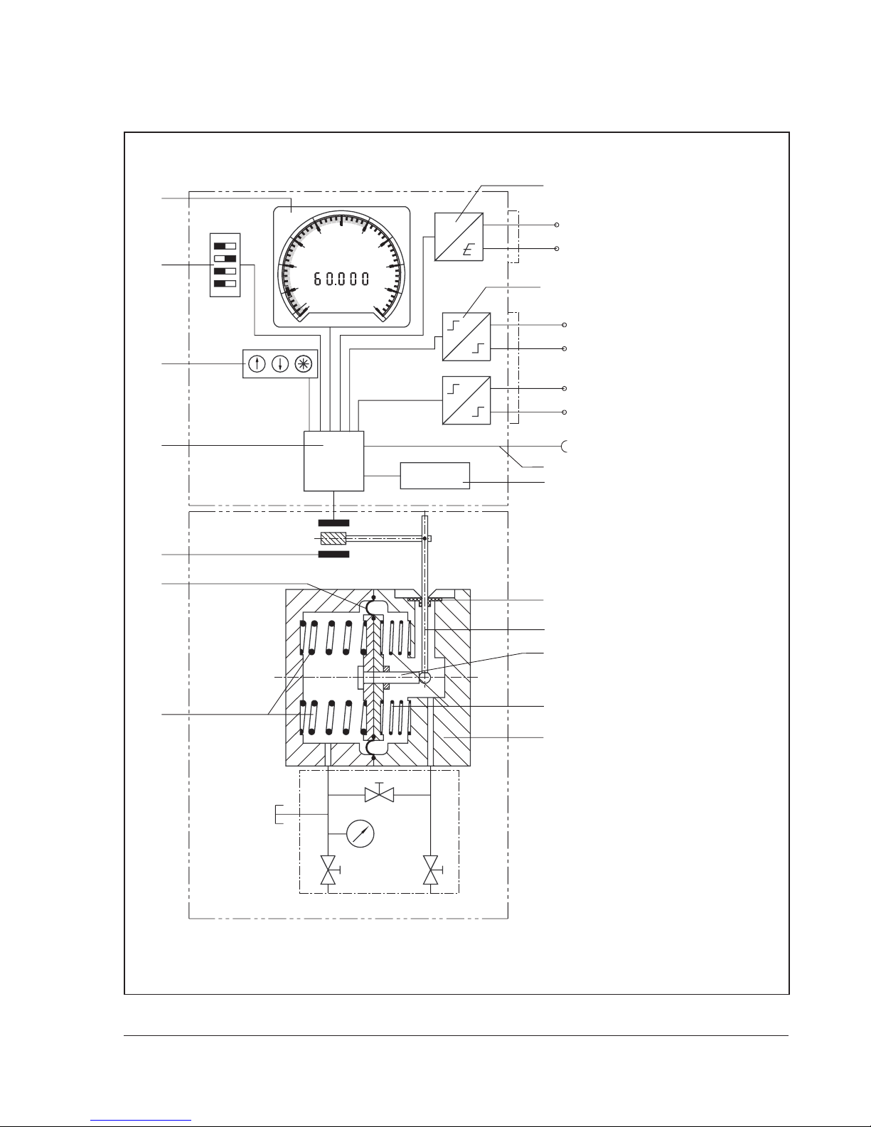
The differential pressure ∆p=p1 – p2creates
a force at the measuring diaphragm (1.1),
which is opposed by the range springs (1.2).
The movement of the measuring diaphragm
and lever (1.3), which is proportional to the
differential pressure, is transmitted by the
elastic disk (1.4) out of the pressure chamber
and converted into an electric signal by the
travel sensor (2).
Based on the evaluation of the data saved in
the FRAM (4), the electric signal is processed
by a microprocessor (3). It controls both the
LCD (7) and the D/A converter (9) for the
output signal, which is issued as a 4 to
20mA two-wire transmitter signal at con-
nector A.
The serial interface (10) allows the device to
be congured with the TROVIS-VIEW soft-
ware using a special memory pen or a cable
connection to a computer. The user-specic
data are saved in the memory (FRAM) (4).
Data backup is also possible. The data re-
main saved until they are overwritten again.
This allows operating data to be easily ex-
changed on site between Media 6 and the
memory pen, and vice versa. The memory
pen can be programmed on a computer us-
ing the TROVIS-VIEW software.
The operating data allow the differential
pressure to be converted into values propor-
tional to the tank capacity or ow rate 2) and
displayed or issued as a 4 to 20mA signal.
The DIP switches (6) are used to select four
saved gas types and different write protec-
tion functions for saved data.
Three operating keys (5) are used to adjust
different operating functions (zero and span
adjustment, lling limit during operation,
limit contacts, and test function settings etc.)
as well as set different operating states (load
or save operating values).
1) Operating mode: liquid level measurement
2) Counting pulse (Media 6 Z)

EB 9527-3 EN 9
Design and principle of operation
Fig.1: Functional diagram
Min./max. alarm A1
Serial interface
Indicating unit with LCD
1Differential pressure cell
1.1 Measuring diaphragm
1.2 Range spring
1.3 Lever
1.4 Flexible disk
1.5 Diaphragm stem
2Travel sensor
3Microprocessor
4Data memory (FRAM)
5Operating keys
6 Four DIP switches (for select-
ing gas type, span protection
and write protection)
7Indicating unit with LCD
8Limit switch and pulse output
9D/A converter
10 RS-232 interface
Connector B
Min./max. alarm A2 or pulse
output (Media6Z)
Connector A
UB=12 to 36VDC
IA=4 to 20mA
FRAM
μP
dp cell
Valve block
with pressure
gauge
0
20
40 60
80
100
%
m3
#
7
6
5
3
2
1.1
1.2
9
8
10
1.5
4
1.4
1.3
1.2
1
p2p1
_+

10 EB 9527-3 EN
Design and principle of operation
3.1 Technical data
Table2: Technical data
All pressure in bar (gauge)·All errors and deviations are specied in % of the adjusted measuring span
Media6 Differential Pressure Meter
Measuring range in mbar 0 to
100
0 to
160
0 to
250
0 to
400
0 to
600
0 to
1000 1)
0 to
1600 1)
0 to
2500 1)
0 to
3600 1)
Adjustable measuring span in mbar
Class ±1% to
from –––≤400
≥100
≤600
≥150
≤1000
≥250
≤1600
≥320
≤2500
≥500
≤3600
≥720
Class ±1.6% to
from – – ≤250
≥125
<100
≥80
<150
≥120
<250
≥200 – – –
Class ±2.5%
to
from
<60
≥352)
<60
≥32
<125
≥50 ––––––
to
from
≤100
≥60
<160
≥160 –––––––
Nominal pressure PN 50, overloadable on one side up to 50 bar
Display LCD Ø 90mm
Characteristic Output and reading linear or square root extraction depending on operating
mode
Deviation from terminal-based
linearity
<±1.0% to <±2.5% (including hysteresis)
depending on measuring span selected
Sensitivity <0.25% or <±0.5% depending on measuring span selected
Effect of static pressure <0.03%/1 bar
Effect of ambient temperature
in the
range from –20 to +70°C
on zero
on span
<±0.2%/10K
<±0.2%/10K
Limit contacts Two congurable software limit contacts or one software limit contact acc. to
EN60947-5-6 and pulse output 5)
Control circuit, in 1% steps Specications corresponding to connected switching amplier 3)
Switching accuracy 1% based on MCN or SCN 4)
Dead band, approx. <0.6%
Pulse output 5) Max. possible counting frequency: 120 pulses/min or 7200 pulses/h 6)
Floating transistor contact for connection of external counter
Input voltage UDC 50V
Input current IDC 80mA
Residual current Ioff <0.1mA
Voltage drop at 10mA <3.5V
Voltage drop at 80mA <4.8V
Pulse length Ton 200ms

EB 9527-3 EN 11
Design and principle of operation
Permissible ambient temperature
range –40 to +70°C T6: –20 to +60°C
T5: –20 to +70°C
Perm. storage temperature range –40 to +80°C
Use of Media6 with gaseous
oxygen
Max. temperature: +60°C
Max. oxygen pressure: 30bar
Degree of protection according to
EN60529 IP65
Weight Approx. 3kg without valve block
Approx. 5kg with valve block
Version 5006- ... 0 5006- ... 1
Two-wire connection 4 to 20mA output
Perm. load RB in Ω RB=(UB–12V)/0.020A
Output circuit –Intrinsically safe acc. to PTB00 ATEX
2074 (see test certicate)
Power supply UB for two-wire
transmitter 12 to 36VDC 12 to 28VDC (only in conjunction
with an intrinsically safe circuit)
Battery operation 7)
Power supply 9VDC (6 x 1.5V LR6 alkaline batteries)
1) A class accuracy of 0.6% can be expected in these measuring ranges with measuring spans ≤100% to ≥50% of the
nominal range.
2) The accuracy of class 2.5 can be exceeded when this measuring span is not reached.
3) e.g. KFA6-SR2-Ex2.W according to EN60947-5-6
4) MCN=Maximum tank content; SCN =Tank content up to overow.
5) Pulse output only with Media6 Z.
6) Determined ow rate is as follows: Q=
7) Battery operation only possible for level measurement and level measurement for transportation vehicles. The A1
and A2 limit contacts are deactivated.
Table3: Materials
Media6 Differential Pressure Meter
dp cell CW617N (brass) or CrNi steel
Measuring diaphragm and seals ECO, NBR, FPM, EPDM
Springs, diaphragm plates and
functional parts, lever CrNi steel
Housing of indicating unit Polycarbonate
Difference of counts within reading period · Qmax
Pulse/h

12 EB 9527-3 EN
Installation
The Media6 is not approved for measuring ammable gases or liquids in hazardous areas
of Zone 0.
Devices intended to measure gaseous oxygen are labeled:
Oxygen! Keep free of oil and grease!
These versions are cleaned and assembled under special conditions. When replacing parts
that come into contact with gaseous oxygen, e.g. range springs, wear suitable gloves and
make sure that the parts do not come into contact with oil or grease.
When returning devices for oxygen service for repair, the sender assumes full responsibility
that the devices are handled to meet all requirements stipulated by VBG62 or similar
regulations until they are handed over to the manufacturer. Otherwise, SAMSON AG does
not accept any responsibility.
NOTICE
!
4 Installation
See Fig.2 on page13.
In arrangements as illustrated by schematic
drawing 2, the additional height z is includ-
ed in the measurement. As a result, this
height must be as low as possible.
The dimension K (compensation height) illus-
trated in schematic drawing 3 can be as
large as required by the conditions in the
plant.
4.1 Arrangement of devices for
ow rate measurement
The decision whether the meter is to be
mounted above or below the measuring
point or whether compensation chambers
are required depends on the process medi-
um and the specic conditions in the plant.
The installation drawing shows standard and
reverse installation. Standard installation is
preferable in any case. Reverse installation
can only be used when there is no other pos-
sibility, particularly for steam measurements.
Refer to VDE/VDI 3512 Sheet 1 for details.
4.2 Media6 indicating unit
Make sure that the high-pressure line is con-
nected to the high-pressure connection and
the low-pressure line is to the low-pressure
connection.
Special screw ttings are required to connect
the differential pressure lines. Depending on
the device arrangement, seal any connec-
tions left unused with stoppers or vent plugs.

EB 9527-3 EN 13
Installation
Liquid level measurement
Illustration with SAMSON valve block
Flow rate measurement
Measurement of liquids Measurement of steam Measurement of gases
Installation
Standard Reverse Standard Standard Reverse
1) SAMSON valve blocks can be mounted upside down to ensure the assignment of plus (+) to plus (+) and minus
(–) to minus (–) remains unchanged.
Fig.2: Arrangement of devices
h
H
z
h
Hh
K
H
Y
+– +–
+–
HMeasuring range
h Measured height
z Additional height
K Compensation height
1) 1) 1)
Orice ange (orice plate assembly) Compensation chamber
Separation chamber
Diagram1
Measurements in cryogenic systems
(liqueed gases)
Diagram2
Measurement on pressure vessels
with condensing or non-condensing
pressure cushion
Diagram3
Measurements on open vessels with
the meter located in a low position

14 EB 9527-3 EN
Installation
Carefully clean the connections before at-
taching the differential pressure lines. Do not
rinse the device with compressed air or pres-
surized water.
Mount the device to a pipe, wall or mounting
plate free of vibration.
Use mounting part with clamp for pipe
mounting to attach it to a vertical or horizon-
tal pipe. Use a mounting part without clamp
for wall mounting. A bracket is required for
for panel mounting (see section 12 on
page37).
4.3 Differential pressure lines
Install the differential pressure lines (pipes
with 12mm outside diameter) as shown in
Fig.3. Make sure you observe the proper or-
der. Use appropriate screw ttings to ensure
that the lines do not leak.
Install line sections, which would usually run
horizontally, with a constant downward
slope of at least 1:20, starting the slope ei-
ther at the orice plate or at the point where
venting is possible. The smallest permissible
bending radius is 50mm. Thoroughly ush
the differential pressure lines before connect-
ing them to the device. Make sure that the
high-pressure line is connected to the
high-pressure connection and the low-pres-
sure line is to the low-pressure connection.
4.4 Orice ange (orice plate
assembly)
The direction of ow must correspond to the
arrow on the orice plate. Unobstructed pipe
sections are required upstream and down-
stream of the orice plate assembly. For the
orice tubes delivered by SAMSON, these
section are ensured by the weld-on calibra-
tion pipes. For orice anges, the unobstruct-
ed pipe section upstream of the orice plate
is specied in the order conrmation. Make
sure the orice plate assembly as well as the
gaskets are properly aligned with the pipe-
line.
Location of the differential pressure lines on the orice plate
assembly
Fig.3: Orice ange (orice plate assembly)
Type 90 Orice Flange
Inlet 20 to 50xd
Outlet 5xd For gas For steam For liquids
The maximum permissible operating
pressure for Type90 is 40bar in the
standard version.
NOTICE
!

EB 9527-3 EN 15
Installation
Do not install any control valves that con-
stantly change the operating state of the pro-
cess medium (e.g. manually operated control
valves or temperature regulators) upstream
of the orice plate assembly. The operating
state must match the conditions calculated
during sizing as closely as possible. It is,
however, favorable to install equipment that
keep the operating state constant (e.g. pres-
sure regulators) upstream of the assembly.
4.4.1 Accessories
We recommend installing a shut-off valve in
the differential pressure lines as well as an
equalizing valve. They can be used to shut
off both differential pressure lines and to by-
pass the indicating unit when checking zero.
4.4.2 Valve block
A valve block comprising three valves (see
Fig.4) is available. It is bolted directly to the
bottom of the dp cell.
When measuring the ow rate of liquids and
gases, the SAMSON valve block can also be
mounted upside down. As a result, the as-
signment of plus (+) to plus (+) and minus (–)
to minus (–) remains unchanged. Due to this
reverse installation, the pressure gauge con-
nection can no longer be used and must be
sealed with an O-ring and a G½-LH screw
cap.
Liquid level measurement Flow rate measurement
Fig.4: SAMSON valve block
Fig.5: Arrangement of shut-off valves and
equalizing valves for ow rate
measurement
–+
1
2
Pressure gauge connection Connection for
measuring lines
To the indicating unit
Hole for leading screw
Equalizing valve
Test connection
Shut-off valve (–) Shut-off valve (+)
From the measuring point
1Shut-off valves
2Equalizing valve

16 EB 9527-3 EN
Installation
4.4.3 Shut-off and equalizing
valves
As an alternative to the SAMSON valve
block, the two shut-off valves as well as the
bypass valve/equalizing valve can also be
installed as illustrated in Fig.5.
4.4.4 Compensation chambers
Compensation chambers that establish a
constant liquid column are required when
measuring steam. When measuring liquids,
they are only required when the indicating
unit is mounted above the measuring point.
For gas measurements, separation chambers
are required for condensate separation
when the indicating unit is installed below
the measuring point.
4.4.5 Accessories for connec-
tion
The devices are delivered without screw t-
tings (oxygen versions are protected against
contamination by four NBR blanking plugs).
Required screw ttings, screw plugs or vent
screws as well as screw joints with restric-
tions to dampen medium-induced vibration
(particularly when measuring gases) must be
ordered separately.
The screw ttings and SAMSON valve blocks
with their associated order numbers are list-
ed in Data Sheet uT9555.
Tip

EB 9527-3 EN 17
Electrical connection
5 Electrical connection
For electrical installation, observe the relevant electrotechnical regulations and the accident
prevention regulations that apply in the country of use. In Germany, these are the VDE regu-
lations and the accident prevention regulations of the employers’ liability insurance.
The following regulation applies to installation in hazardous areas: EN60079‑14 (VDE
0165‑1) Electrical Apparatus for Explosive Gas Atmospheres.
For intrinsically safe electrical equipment approved in accordance with Directive 94/9/EC
(2014/34/EU from 20 April 2016), the data specied in the EC type examination certicate
apply to the connection of intrinsically safe circuits.
Adhere to the terminal assignment specied in the certicate. Switching the assignment of the
electrical terminals may cause the explosion protection to become ineffective. Do not loosen
enameled screws in or on the housing.
In hazardous areas, only use an ammeter approved in accordance with ATEX to measure the
current at the test connection (TEST).
The serial interface is not approved for use in hazardous areas. As a result, only the intrinsi-
cally safe SAMSON memory pen must be connected to transfer data.
Selection of cables and wires · Observe section 12 in EN60079‑14 (VDE0165) when run-
ning several intrinsically safe circuits in one multi-core cable. The radial thickness of the insu-
lation of a conductor for common insulating materials (e.g. polyethylene) must not be smaller
than 0.2mm. The diameter of an individual wire in a ne‑stranded conductor must not be
smaller than 0.1mm. Protect the conductor ends against splicing, e.g. by using wire‑end fer-
rules. When two separate cables are used for connection, an additional cable gland can be
installed. Seal cable entries left unused with plugs. Fit equipment used in ambient tempera-
tures below –40°C with metal cable entries.
GEFAHR
!WARNING
!
NOTICE
!

18 EB 9527-3 EN
Electrical connection
5.1 Device connector
Connector A·Power supply
The same pair of conductors transmit the 4
to 20mA measuring signal and the required
power supply (UB=12 to 36V) for the two-
wire transmitter.
The Media 6 is connected over a
DINEN175301-803 connector, type A,
4-pole.
Two-wire connection for 4 to 20mA current
signal:
RB=UB–12V in Ω
0.020A
Rated power supply UB=24VDC. Taking
the resistance of the supply leads directly at
the terminals of the connector into account, it
must be between 12 and 36VDC.
Optionally, battery operation possible with
9VDC power supply
Connector B·Limit contacts/pulse output
Connection of two software limit contacts in
type of protection ExiaIIC for control circuits
according to NAMUR on switching amplier
according to EN60947-5-6
Max. values:
Ui=20 V, Ii=60mA, Pi=250 mW
Ci=5.3 nF, Li=8μH
Media6Z includes only one software limit
contact (alarm 1) and one pulse output (in-
stead of alarm 2/contacts 3 and 4), which is
proportional to the tank capacity, to control
an external counter.
Test connection
Connect an ammeter to the test terminals +
and – to test the output signal during cali-
bration. The output signal of the two-wire cir-
cuit is not interrupted during this procedure.
Make sure that the ammeter provides a load
of < 0.4VDC for the test connection.
Connector A
Two-wire connection for 4 to
20mA current signal and power
supply UB
Cable socket
Order no.: 8831-0503
Connector connections for cable
with 8 to 10mm diameter
Connector B
Two software limit contacts or one
software limit contact and a pulse
output (Media6Z)
Cable socket
Order no.: 8831-0500
Fig.6: Terminal assignment of DINEN175301‑803 connector, type A
1
3
2
4
1+
2–
3+
4–
~
1+
2–
1
3
2
Min./max. A1
Min./max. A2
Limit contacts with switching amplier
Supply unit
Power

EB 9527-3 EN 19
Operation
−Degree of protection IP65 is no longer valid when the cable socket is removed from the
device connector.
−Protect the device connector against moisture during installation and transport by keeping
the cable socket part screwed on and sealed.
Table4: Overview of functions of both software limit contacts A1 and A2 at connector B
Proximity switch
for ...
1min./1max. contact
(gas withdrawal/tank lling)
Two min. contacts
(gas withdrawal)
Two max. contacts
(tank lling)
Alarm contact A1 A2 A1 A2 A1 A2
Value below limit High
resistance Low resistance High
resistance
High
resistance Low resistance Low resistance
Value above limit Low resistance High
resistance Low resistance Low resistance High
resistance
High
resistance
Both limit contacts A1/A2 can be congured separately as minimum or maximum alarms.
Both limit contact outputs A1 and A2 are deactivated during battery operation.
Contact with low resistance
Switching signal ON · Function: Contact closed or output effectively conducting, power con-
sumption ≥ 3mA
Contact with high resistance
Switching signal OFF · Function: Contact opened or output effectively non-conducting, power
consumption ≥ 1mA
6 Operation
6.1 Display and operating controls
All necessary data and measured values saved in the memory of Media 6 are indicated on
the LCD.
The operating controls are located on the bottom panel behind the protective cover, which
can be opened:
Four DIP switches to select the gas type and write protection functions (see Fig.7 on
page24) are located next to them.
GEFAHR
!WARNING
!
Note
Up key Down key Enter key

20 EB 9527-3 EN
Operation
Further details on the display and operating controls can be found at the back of these in-
structions.
6.1.1 Switching over to display mode
Depending on the operating mode, each pressing of the key allows you to switch between
the default display and up to eight other display readings.
After eight seconds or after the text has nished running across the display, the display auto-
matically returns to the default display.
GKZ Default mode (e.g. gas code (O2) and actual content)
∆p Current differential pressure
MCN Max. capacity nominal
MCN/R 100% tank volume or max. possible ow rate at 20mA signal
SCN Save capacity nominal. Geometric tank volume up to overow/gauge pipe.
SCN/R 100% tank volume at 20mA signal
UCW Useable capacity work
Δp100 Maximum differential pressure
Δp0 Minimum differential pressure
PTANK Nominal tank pressure. Value corresponds to the pressure assigned to the density (liquid)
according to the steam pressure graph. If MCN and SCN are calculated on the basis of
1bar, '1 bar' is displayed for PTANK.
TKZ Tank/plant identier
FLOW Flow rate
ERROR Error code automatically displayed in the event of an error (see section10).
OFF Special signal on opening the equalizing valve, I=3.6mA
LOW BAT Special signals in battery operation
BAT MODE Battery mode
EMS Power-saving mode (ESM). 4 to 20mA signal deactivated.
This manual suits for next models
1
Table of contents
Other Samson Measuring Instrument manuals

Samson
Samson Media 6 Service manual

Samson
Samson 411 120 Operating manual

Samson
Samson Media 7 5007-1 Service manual

Samson
Samson Media 6 Service manual

Samson
Samson 024.85 User manual

Samson
Samson 2100 Series Troubleshooting guide

Samson
Samson Media 7 Service manual

Samson
Samson Media 05 Service manual

Samson
Samson 411 110 Operating manual

Samson
Samson 1100 SERIES User manual