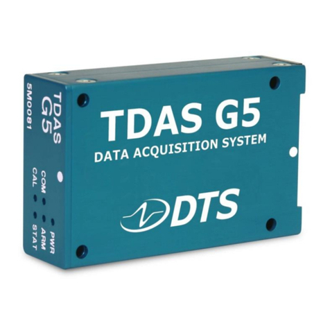
TIERRA AM35 Series User manual

1
TABLE OF CONTENTS
PREFACE ............................................................................................................. 2
INTRODUCTION .................................................................................................. 4
SPECIFICATIONS ................................................................................................. 8
INSTALLATION ................................................................................................... 12
BATTERY PACK WARNINGS .............................................................................. 18
TROUBLESHOOTING ......................................................................................... 19
TECHNICAL SUPPORT....................................................................................... 20
LINK TO USER GUIDE ........................................................................................ 21
CERTIFICATIONS ............................................................................................... 22

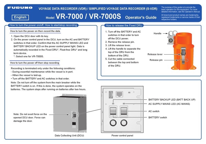
TERMS AND CONDITIONS
32
PREFACE
Thank you for purchasing this Tierra product. The materials available in this Manual (the “Manual”) have been
prepared by Tierra S.p.A. (“Tierra”) for customers of Tierra products, and are designed to assist customers with
the use of the receiver and its use is subject to these terms and conditions (the “Terms and Conditions”).
NOTICE - Please read these Terms and Conditions
carefully.
USE This product is designed to be used by a professional. The user should have a good knowledge of the safe use
of the product and implement the types of safety procedures recommended by the local government protection
agency for both private use and commercial job sites.
COPYRIGHT All information contained in this Manual is the intellectual property of, and copyrighted material of
Tierra S.p.A. All rights are reserved. You may not use, access, copy, store, display, create derivative works of, sell,
modify, publish, distribute, or allow any third party access to, any graphics, content, information or data in this
Manual without Tierra’s express written consent and may only use such information for the care and operation
of your receiver. The information and data in this Manual are a valuable asset of Tierra and are developed by
the expenditure of considerable work, time and money, and are the result of original selection, coordination and
arrangement by Tierra.
TRADEMARKS Tierra is a registered trademark. Other product and company names mentioned herein may be
trademarks of their respective customers.
DISCLAIMER OF WARRANTY EXCEPT FOR ANY WARRANTIES IN AN APPENDIX OR A WARRANTY CARD
ACCOMPANYING THE PRODUCT, THIS MANUAL AND THE RECEIVER ARE PROVIDED “AS‐IS.” THERE ARE
NO OTHER WARRANTIES. TPS DISCLAIMS ANY IMPLIED WARRANTY OF MERCHANTABILITY OR FITNESS FOR
ANY PARTICULAR USE OR PURPOSE. TIERRA AND ITS DISTRIBUTORS SHALL NOT BE LIABLE FOR TECHNICAL
OR EDITORIAL ERRORS OR OMISSIONS CONTAINED HEREIN; NOR FOR INCIDENTAL OR CONSEQUENTIAL
DAMAGES RESULTING FROM THE FURNISHING, PERFORMANCE OR USE OF THIS MATERIAL OR THE
RECEIVER. SUCH DISCLAIMED DAMAGES INCLUDE BUT ARE NOT LIMITED TO LOSS OF TIME, LOSS OR
DESTRUCTION OF DATA, LOSS OF PROFIT, SAVINGS OR REVENUE, OR LOSS OF THE PRODUCT’S USE. IN
ADDITION, TIERRA IS NOT RESPONSIBLE OR LIABLE FOR DAMAGES OR COSTS INCURRED IN CONNECTION
WITH OBTAINING SUBSTITUTE PRODUCTS OR SOFTWARE, CLAIMS BY OTHERS, INCONVENIENCE, OR ANY
OTHER COSTS. IN ANY EVENT, TPS SHALL HAVE NO LIABILITY FOR DAMAGES OR OTHERWISE TO YOU OR
ANY OTHER PERSON OR ENTITY IN EXCESS OF THE PURCHASE PRICE FOR THE RECEIVER.
LICENSE AGREEMENT Use of any computer programs or software supplied by Tierra or downloaded from a Tierra
website (the “Software”) in connection with the receiver constitutes acceptance of these Terms and Conditions
in this Manual and an agreement to abide by these Terms and Conditions. The user is granted a personal, non‐
exclusive, non‐transferable license to use such Software under the terms stated herein and in any case only with a
single receiver or single computer. You may not assign or transfer the Software or this license without the express
written consent of Tierra. This license is effective until terminated. You may terminate the license at any time by
destroying the Software and Manual. Tierra may terminate the license if you fail to comply with any of the Terms
or Conditions. You agree to destroy the Software and manual upon termination of your use of the receiver. All
ownership, copyright and other intellectual property rights in and to the Software belong to Tierra. If these license
terms are not acceptable, return any unused software and manual.
This manual uses the following conventions:
MANUAL CONVENTIONS
CONFIDENTIALITY This Manual, its contents and the Software (collectively, the “Condential Information”) are
the condential and proprietary information of Tierra. You agree to treat Tierra’s Condential Information with a
degree of care no less stringent that the degree of care you would use in safeguarding your own most valuable
trade secrets. Nothing in this paragraph shall restrict you from disclosing Condential Information to your
employees as may be necessary or appropriate to operate or care for the receiver. Such employees must also
keep the Condentiality Information condential. In the event you become legally compelled to disclose any of
the Condential Information, you shall give Tierra immediate notice so that it may seek a protective order or other
appropriate remedy.
WEBSITE; OTHER STATEMENTS No statement contained at the Tierra website (or any other website) or in any
other advertisements or Tierra literature or made by an employee or independent contractor of Tierra modies
these Terms and Conditions (including the Software license, warranty and limitation of liability).
SAFETY Improper use of the receiver can lead to injury to persons or property and/or malfunction of the product.
The receiver should only be repaired by authorized Tierra warranty service centers. Users should review and heed
the safety warnings in an Appendix.
MISCELLANEOUS The above Terms and Conditions may be amended, modied, superseded, or canceled, at any
time by Tierra.
PREFACE
NOTE - Further information to note about the
conguration, maintenance, or setup of a system.
TIPS - Supplementary information that can help you
congure, maintain, or set up a system.
NOTICE - Supplementary information that can have
an effect on system operation, system performance,
measurements, or personal safety.
WARNING - Notication that an action will result
in system damage, loss of data, loss of warranty, or
personal injury.
DANGER - Under no circumstances should this action
be performed.

54
INTRODUCTION
AM35 Series is Tierra’s third generation of devices and the result of our long-standing expertise in providing
advanced telematics and bringing meaningful improvements in our HW to keep on meeting our customers’
necessities.
Three versions of AM35 have been designed to suit the market requirements.
• AM35XT with Bluetoth/WiFi and internal antennas
• AM35XB with Bluetoth/WiFi and external antennas
• AM35LT with internal antennas
INTRODUCTION
REFERENCE PART NUMBER
Part Numbers Model Modem Version
1048872-01 AM35XT EC21E
1048872-02 AM35LT EC21E
TRR-322C23 AM35LT EC21E
1048873-01 AM35XT EC21A
1048873-02 AM35LT EC21A
1048874-01 AM35XT EC21AU
1048874-02 AM35LT EC21AU
xxxx AM35XB xxxxx
xxxx AM35XB xxxxx
xxxx AM35XB xxxxx
xxxx AM35XB xxxxx

6 7
INTRODUCTION INTRODUCTION
Power LED (Red):
•OFF - No power supply.
•Double blink - powered and working.
•Rapid blinking - key off.
CAN-BUS LED (green):
•Off: CAN-BUS signal not available.
•Solid On: can messages received from at least one line.
MODEM LED (green):
•Off: Modem initialization phase. No network coverage or device in standby/wake mode.
•Slow Blink: GSM networks detected.
•Fast Blink: Device connected to the network, and ready to communicate with the server.
•On solid: GSM communication ongoing.
GPS LED (green):
•Off: GPS initialization phase or device in standby/wake mode.
•Blinking: Searching for GPS signal.
•On solid: GPS x completed.
AM35 LED DISPLAY PANEL AM35 MAIN ENVELOPE DIMENSIONS
Specic scenarios
BOOT: All leds are lights up for the boot time
FACTORY LOOP: Power LED (red) xed on and three green LEDs are OFF. At Key off, the device goes to
hibernate, and every LEDs will be OFF.

98
SPECIFICATIONS
SPECIFICATIONS
AM35XT AM35XB
Wakeup sources Ignition - RTC - CAN - IMU
SIM Onchip transformable RSP 3.2 compliant
WiFi/BLE WiFi 2.4 GHz, 11b/g/n20: 2412 ÷ 2472 MHz - BT/BLE 4.1: 2402 ÷ 2480 MHz
Memory
RAM 30 MB - extended memory +8MB
Flash NAND 90 MB - extended memory +128 MB
LED x4
Ports & Connectors
Serial Port[1] RS232
CAN Bus 2x with congurable 120 Ohm termination
Connector
Built-in harness
Cellular technologies
multi-mode modem
Regional variants:
- North America: LTE B2, B4, B12; WCDMA B2/B4/B5 – Verizon: LTE B4, B13
- Latin America/Australia: LTE B1, B2, B3, B4, B5, B7, B8, B28, B40; WCDMA B1/B2/B5/B8;
GSM/EDGE B2/B3/B5/B8 and 2G support
- Europe/East Asia: LTE B1, B3, B7, B8, B20; WCDMA B1/B5/B8; GSM/EDGE B3/B8 and 2G
support - Global 3G support
RF Output power
Bluetooth 6.8 dBm; BLE: 0.4 dBm
11b/17.8 dBm, 11g: 15.9 dBm, 11n20: 14.7 dBm, 11n40: 12.9 dBm
11ac (20MHz): 11.95dBm, 11ac (40 MHz): 9.96 dBm, 11 ac (80MHz): 9.96 dBm
E-GSM 900 33 dBm; DCS1800: 30 dBm; UMTS Band I: 23 dBm; UMTS Band VIII: 23 dBm; LTE Band
1/3/7/8/20: 23dBm
Antennas (Internal) GNSS - WiFi - LTE
GNSS Receiver
Frequency GPS QZSS (Optional) GLONASS BeiDou Galileo
Motion Sensor 6-Axis Accelerometer and gyroscope
Input/Output
Input Device Digital/Analog/Frequency (software congurable): 4x
Output Devices
2x HS and 2x LS - 0.5 A max - short circuit protected - latched
Power Supply
Input 12-24 V DC, 0.5 A max
Battery NiMH 7.2 Vdc, 400 mAh
Ground and battery (KL30) - Voltage: 9 to 36V
Switched power (KL15) or Alternator W - Voltage: 9 to 36V
Batteries
NiMH Battery Charging time: 10 hours Capacity: 3 Wh
Remote Capabilities
Conguration Yes
Firmware Update
[2]
Yes (OTA)
Environmental
[3]
Water/Dust Resistance
IP67 IP69K
Operating Temperature
Range[4]
-40°C
to +85°C
Humidity 5 to 95% RH
Physical
Dimensions L: 105 mm x W: 76 mm x H: 35 mm
Weight (with internal
batteries) 275g
[1] Debug Software or rmware customization.
[2] With the exception of downloading time, updates are performed during normal usage.
[3] Totally protected against dust and the effect of immersion up to 39.3701” deep (1m).
[4] With the exception of battery recharging process.
Wakeup sources Ignition - RTC - CAN - IMU
SIM Onchip transformable RSP 3.2 compliant
WiFi/BLE WiFi 2.4 GHz, 11b/g/n20: 2412 ÷ 2472 MHz - BT/BLE 4.1: 2402 ÷ 2480 MHz
Memory
RAM 30 MB - extended memory +8MB
Flash NAND 90 MB - extended memory +128 MB
LED x4
Ports & Connectors
Serial Port[1] RS232
CAN Bus 2x with congurable 120 Ohm termination
Connector
Built-in harness
Cellular technologies
multi-mode modem
Regional variants:
- North America: LTE B2, B4, B12; WCDMA B2/B4/B5 – Verizon: LTE B4, B13
- Latin America/Australia: LTE B1, B2, B3, B4, B5, B7, B8, B28, B40; WCDMA B1/B2/B5/B8;
GSM/EDGE B2/B3/B5/B8 and 2G support
- Europe/East Asia: LTE B1, B3, B7, B8, B20; WCDMA B1/B5/B8; GSM/EDGE B3/B8 and 2G
support - Global 3G support
RF Output power
Bluetooth 6.8 dBm; BLE: 0.4 dBm
11b/17.8 dBm, 11g: 15.9 dBm, 11n20: 14.7 dBm, 11n40: 12.9 dBm
11ac (20MHz): 11.95dBm, 11ac (40 MHz): 9.96 dBm, 11 ac (80MHz): 9.96 dBm
E-GSM 900 33 dBm; DCS1800: 30 dBm; UMTS Band I: 23 dBm; UMTS Band VIII: 23 dBm; LTE Band
1/3/7/8/20: 23dBm
Antennas
External
GNSS - LTE Main - LTE Diversity (Fakra connectors)
Internal
WiFi - BLE
GNSS Receiver
Frequency GPS QZSS (Optional) GLONASS BeiDou Galileo
Motion Sensor 6-Axis Accelerometer and gyroscope
Input/Output
Input Device Digital/Analog/Frequency (software congurable): 4x
Output Devices
2x HS and 2x LS - 0.5 A max - short circuit protected - latched
Power Supply
Input 12-24 V DC, 0.5 A max
Battery NiMH 7.2 Vdc, 400 mAh
Ground and battery (KL30) - Voltage: 9 to 36V
Switched power (KL15) or Alternator W - Voltage: 9 to 36V
Batteries
NiMH Battery Charging time: 10 hours Capacity: 3 Wh
Remote Capabilities
Conguration Yes
Firmware Update
[2]
Yes (OTA)
Environmental
[3]
Water/Dust Resistance
IP67 IP69K
Operating Temperature
Range[4]
-40°C
to +85°C
Humidity 5 to 95% RH
Physical
Dimensions L: 105 mm x W: 76 mm x H: 35 mm
Weight (with internal
batteries) 290g
[1] Debug Software or rmware customization.
[2] With the exception of downloading time, updates are performed during normal usage.
[3] Totally protected against dust and the effect of immersion up to 39.3701” deep (1m).
[4] With the exception of battery recharging process.

10 11
SPECIFICATIONS
AM35LT
SPECIFICATIONS
Wakeup sources Ignition - RTC - CAN - IMU
SIM Onchip transformable RSP 3.2 compliant
WiFi/BLE No
Memory
RAM 30 MB - extended memory +8MB
Flash NAND 90 MB - extended memory +128 MB
LED x4
Ports & Connectors
Serial Port[1] RS232
CAN Bus 2x with congurable 120 Ohm termination
Connector
Built-in harness
HW Latch Congurable for outputs
Cellular technologies
multi-mode modem
Regional variants:
- North America: LTE B2, B4, B12; WCDMA B2/B4/B5 – Verizon: LTE B4, B13
- Latin America/Australia: LTE B1, B2, B3, B4, B5, B7, B8, B28, B40; WCDMA B1/B2/B5/B8;
GSM/EDGE B2/B3/B5/B8 and 2G support
- Europe/East Asia: LTE B1, B3, B7, B8, B20; WCDMA B1/B5/B8; GSM/EDGE B3/B8 and 2G
support - Global 3G support
RF Output power
Bluetooth No
E-GSM 900 33 dBm; DCS1800: 30 dBm; UMTS Band I: 23 dBm; UMTS Band VIII: 23 dBm; LTE Band
1/3/7/8/20: 23dBm
Antennas (Internal) GNSS - LTE
GNSS Receiver
Frequency GPS QZSS (Optional) GLONASS BeiDou Galileo
Motion Sensor 6-Axis Accelerometer and gyroscope
Input/Output
Input Device Digital/Analog/Frequency (software congurable): 4x
Output Devices
2x HS and 2x LS - 0.5 A max - short circuit protected - latched
Power Supply
Input 12-24 V DC, 0.5 A max
Battery NiMH 7.2 Vdc, 400 mAh
Ground and battery (KL30) - Voltage: 9 to 36V
Switched power (KL15) or Alternator W - Voltage: 9 to 36V
Batteries
NiMH Battery Charging time: 10 hours Capacity: 3 Wh
Remote Capabilities
Conguration Yes
Firmware Update
[2]
Yes (OTA)
Environmental
[3]
Water/Dust Resistance
IP67 IP69K
Operating Temperature
Range[4]
-40°C
to +85°C
Humidity 5 to 95% RH
Physical
Dimensions L: 105 mm x W: 76 mm x H: 35 mm
Weight (with internal
batteries) 275g
[1] Debug Software or rmware customization.
[2] With the exception of downloading time, updates are performed during normal usage.
[3] Totally protected against dust and the effect of immersion up to 39.3701” deep (1m).
[4] With the exception of battery recharging process.

1312
INSTALLATION
INSTALLATION
The following section describes the installation steps for AM35 devices. Vehicle cables and screws
are not included
1. Disconnect the vehicle battery main switch, and maintain it disconnected for the duration of the device
installation process.
2. Install the device using bolts on dedicated mounting holes.
3. Guarantee a full contact of bottom cover toward the vehicle with a at surface. AM35XB can be placed with no
orientation recommendation. AM35XT must be orientated with the top towards the sky to improve the GNSS
internal antenna performance.
4. Guarantee to mount the device in a protected place (e.g. inside the vehicle cabin).
AM35 DEVICES INSTALLATION
WARNING - NEVER cover the vent hole in the bottom of the AM35 device
with tape or Velcro. Covering the vent hole may cause device failure, as the
vent hole releases humidity caused by temperature changes.
Mounting
Holes
Mounting
Holes Vent Hole
5. Connect the vehicle cables to the device through the connectors.
Ensure that the battery line is protected by a 5A automotive fuse.

14 15
INSTALLATION
6. Connect the antenna cables (AM35XB only).
INSTALLATION
INSTALLATION SPECIFICATIONS
NOTICE - If the device is not properly installed, any
motion detected by the internal accelerometer will have
a negative impact. False readings will occur unless the
device is rmly in place.
WARNING - DO NOT ALLOW the CM1X or the
components of the telematic system to BLOCK or LIMIT
your view outside the cab.
Use goggles when drilling, cutting, or grinding on the
machine.
WARNING - To avoid the effects of human exposure
to electromagnetic elds, the device must be installed
at a minimum distance of 20 cm from the vehicle
operator/driver.
Type Fixed
Means Bolt M6
Max Torque 5Nm
Maximum gain: 1 dBi
Minimum distance from user: 20 cm from antenna apparatus
Characteristic impedance: 50 Ohm
7. Connect the vehicle battery.

16 17
INSTALLATION
CONNECTOR PINOUT
Pin # Signal Color
1+30 Red
2+15 Orange
3In0 Brown
4In2 Pink
5CAN1_L Green
6CAN2_L Red/Green
7Out0_LS Red/Black
8Out2_LS White/Black
9RS232_Out Violet
LTE Diversity
GNSS LTE
INSTALLATION
NOTICE - The wiring schematics are noted as recommendations by Tierra, please
consult your equipment manufacturers operation manuals for specic information
pertaining to wiring or use of the equipment’s battery as a power source.
WARNING - Before welding steel parts on the frame, disconnect the AM35 device as
hardware issues may occur.
WARNING - Do not apply external force on the harness and allow the cables to be
tension-free.
WARNING - The switched power wire (orange) should be connected to a source that is
only energized during the engine run cycle.
DO NOT CONNECT RED AND ORANGE WIRES TOGETHER.
If red and orange wires are connected to the same signal source, the Key OFF event
is not detected or reported and the device rmware will not function properly. This
connection can be sourced at the output run terminal of your vehicle’s alternator or other
sources that are only “hot” when the engine is running (mechanical hour meter, etc.). Use
a multimeter to verify that 9 to 36 volts are present only when the engine is ON. For both
switched power (orange) and constant power (red), the voltage range is the same.
CAUTION - Wiring a piece of heavy equipment up without using the above‐mentioned
method causes problems with inaccurate hours being reported into Tierra web. These
hours will not match the hour meter on the machine, thereby causing erroneous readings
due to the presence of a switched power signal when the engine is not running. This
could occur if wired to the ignition when the key switch is left ON. Due to the inability
to detect Key OFF, connecting red and orange to the same signal source is never
acceptable. IN ALL CASES, switched power wired to an engine run signal is the rst and
best practice.
NOTICE - Some vehicles, such as tractors or agricultural machines, have 3‐pin connectors
with ground, battery power, and switched power located inside the cabin. You can use
this connector to power an AM35 device. Both constant power and switched power need
to be fuse‐protected (5A fuse works ne). Install a 5A fuse onto the battery power cable
and another fuse onto the switched power cable if the circuit is not protected.
NOTICE - Use Ty‐wraps to keep hoses and wires secured to avoid possible wear
or pinch points.
NOTICE - Both switched power AND constant power MUST BE used to properly
power up the box.
Pin # Signal Color
10 GND Black
11 Chassis Grey
12 In1 Turquise
13 In3 Blue
14 CAN1_H Yellow
15 CAN2_H Red/Yellow
16 Out1_HS White/Red
17 Out3_HS White/Green
18 RS232_in White

18 19
BATTERY PACK WARNINGS
DANGER - Opening the device by Unauthorized Personal VOIDS the Warranty!
Never attempt to open the casing of the detachable batteries! NiMH batteries can be dangerous
if mishandled!
DANGER - Do not incinerate or heat battery pack above 248°F (120°C). Excessive heat can cause
serious damage and possible explosion.
WARNING - Battery replacement is not allowed.
WARNING - This product contains a NiMH battery that contains Perchlorate Material. Special
handling may apply.
NOTICE - Upon rst connection, you must power the AM35 device for ten (10) hours of normal run
time to fully charge the internal battery.
TROUBLESHOOTING
Connectivity is the most common customer technical issue. Troubleshooting involves a series of tests to isolate the
issue to the main points of failure (outlined below) from which the root cause can be identied, followed by the
resolution. Our trained Tierra Support Technicians can check any provision or coverage area issues and work to
troubleshoot your device remotely.
WARNING - Do not attempt to repair
equipment yourself. Doing so will void your
warranty and may damage the hardware.
CAUTION - Powering off/on the device without
using the orange switched power connection
can cause unwanted behavior.
AM35 DEVICE ISSUES
1. Check that the device has power.
2. Check that the connections for ground, power, and especially switched power are correct.
3. If power management proles do not function, make sure that the internal battery has a full charge (this can take
up to 10 hours initially to put a full charge into the back up battery contained inside Tierra devices).
4. Try to power cycle the device.

20 21
TECHNICAL SUPPORT
If the troubleshooting hints and tips in this Installation Manual fail to remedy the problem, please contact Tierra
Support: [email protected]
When emailing, please provide the following information for better, faster service:
1. The device version.
2. The system/hardware specications for the computer running the Tierra Web Application such as operating
system and version, memory and storage capacity, processor speed, and so forth.
3. The symptoms and/or error codes/messages that precede and follow the problem.
4. The activities being tried when the problem occurs. If possible, include the exact steps being taken up to when
the error message or other problem occurs.
5. How regularly the problem occurs. Generally, a customer support representative will reply within 24 hours,
depending on the severity of the problem.
LINK TO USER GUIDE
Once the device is installed and running, you can access the User Guide at the following link:
http://www.tierratelematics.com/download/AM35InstallationManual.pdf

2322
1. Changes or modications not expressly approved by the party responsible for compliance could void the user’s
authority to operate the equipment.
2. This device model AM35XT/AM35XB/AM35LT contains IC:28545-AM35 and:
IC: 10224A-201611EC21A (Modem version EC21A)
3. Responsible party’s contact located in the Canada:
Name: Stephen Rosenegger
Address: Topcon Positioning Systems Inc, 855-2 Street SW, Suite 3500 Calgary AB T2P 4J8 Canada
Telephone number: +1 403-450-4262
4. This device contains licence-exempt transmitter(s)/receiver(s) that comply with Innovation, Science and Economic
Development Canada’s licence exempt RSS(s). Operation is subject to the following two conditions: (1) This device
may not cause interference. (2) This device must accept any interference, including interference that may cause
undesired operation of the device.
L’emetteur/recepteur exempt de licence contenu dans le present appareil est conforme aux CNR d’Innovation,
Sciences et Developpement economique Canada applicables aux appareils radio exempts de licence. L’exploitation
est autorisee aux deux conditions suivantes : (1) L’appareil ne doit pas produire de brouillage; (2) L’appareil
doit accepter tout brouillage radioelectrique subi, meme si le brouillage est susceptible d’en compromettre le
fonctionnement.
5. ICES-003 Class B Notice -Avis NMB-003 Class B :
This Class B digital device complies with Canadian ICES-003
Cet appareil numerique classe B est conforme à la norme Canadien NMB-003.
CAN ICES-3(B) /NMB-3(B)
ISED
This device complies with Directive 2014/53/EU issued by the Commission of the European Community.
Approval number: E8*10R06/01*13462*00
Approval mark:
RED
ECE-R10
10R-06 13462
8
CERTIFICATIONS
1. Changes or modications not expressly approved by the party responsible for compliance could void the user’s
authority to operate the equipment.
2. This device model AM35XT/AM35XB/AM35LT contains FCC ID: 2A6VC-AM35 and:
FCC ID: XMR201606EC21A (Modem version EC21A)
3.This device complies with part 15 of the FCC Rules. Operation is subject to the following two conditions: (1) This
device may not cause harmful interference, and (2) this device must accept any interference received, including
interference that may cause undesired operation.
4. This equipment has been tested and found to comply with the limits for a Class B digital device, pursuant to part
15 of the FCC Rules. These limits are designed to provide reasonable protection against harmful interference in a
residential installation. This equipment generates, uses and can radiate radio frequency energy and, if not installed
and used in accordance with the instructions, may cause harmful interference to radio communications. However,
there is no guarantee that interference will not occur in a particular installation. If this equipment does cause
harmful interference to radio or television reception, which can be determined by turning the equipment off and
on, the user is encouraged to try to correct the interference by one or more of the following measures:
- Reorient or relocate the receiving antenna.
- Increase the separation between the equipment and receiver.
- Connect the equipment into an outlet on a circuit different from that to which the receiver is connected.
- Consult the dealer or an experienced radio/TV technician for help.
FCC
CERTIFICATIONS
This device complies with Radio Equipment Regulations 2017 (S.I. 2017/1206) of the UK Parliament relating to the
making available on the market of radio equipment.
UCKA

24
Part Number TRR-MAN-01-02
Rev A
© Copyright Tierra S.p.A.
July, 2022
All contents in this manual are copyrighted by Tierra S.p.A. All rights reserved. The information
contained herein may not be used, accessed, copied, stored, displayed, sold, modied, published, or
distributed, or otherwise reproduced without express written consent from Tierra S.p.A.

TIERRA S.p.A.
Corso Ferrucci, 112 - 10138 Torino - Italy
www.tierratelematics.com
This manual suits for next models
9
Table of contents

