manuals.online logo
Brands
  1. Home
  2. •
  3. Brands
  4. •
  5. MadgeTech
  6. •
  7. Data Logger
  8. •
  9. MadgeTech Bridge101A-30 User manual

MadgeTech Bridge101A-30 User manual

This manual suits for next models

3

Other MadgeTech Data Logger manuals

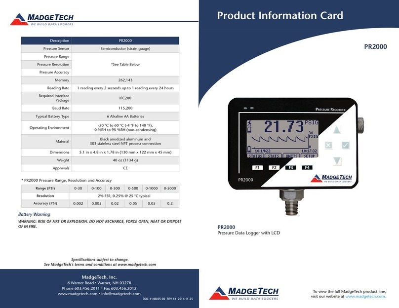
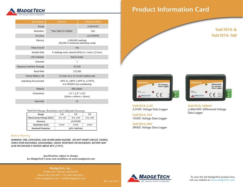
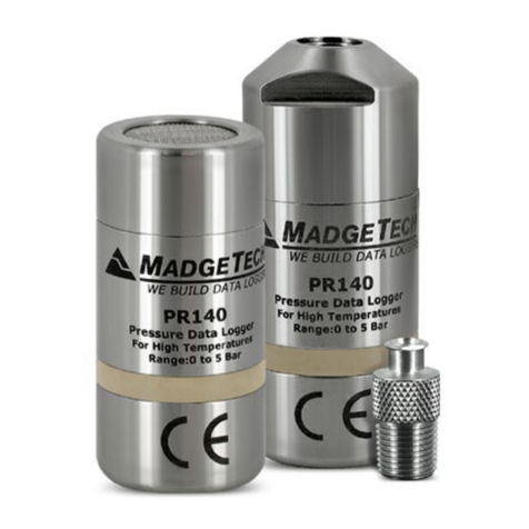
MadgeTech PR1000IS Series Specification sheet

MadgeTech

MadgeTech PR1000IS Series Specification sheet

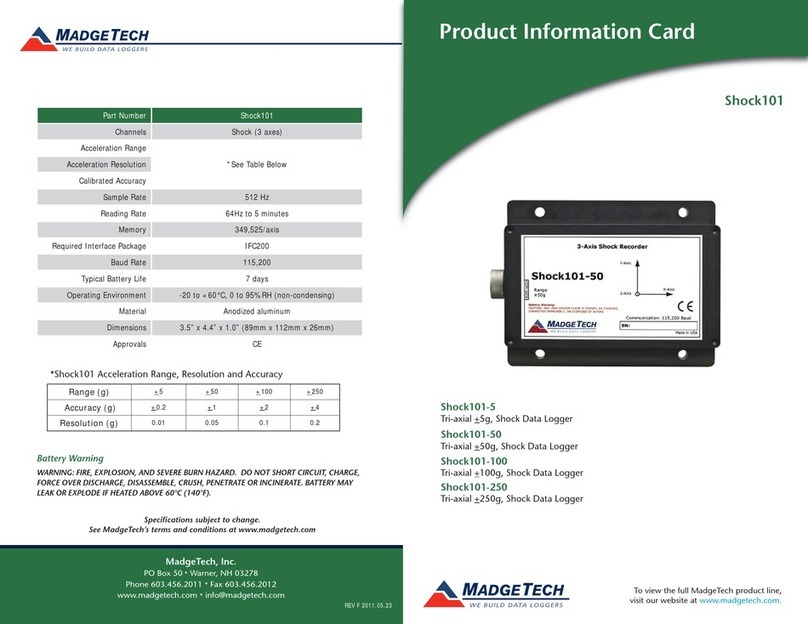
MadgeTech Shock101-100 Specification sheet

MadgeTech

MadgeTech Shock101-100 Specification sheet

MadgeTech RFOT Specification sheet

MadgeTech

MadgeTech RFOT Specification sheet

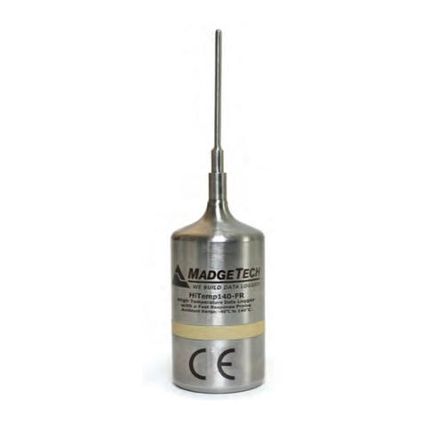
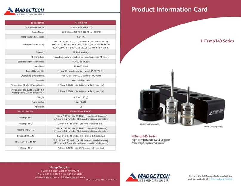
MadgeTech HITEMP140-FR Specification sheet

MadgeTech

MadgeTech HITEMP140-FR Specification sheet

MadgeTech RHTEMP1000IS Specification sheet

MadgeTech

MadgeTech RHTEMP1000IS Specification sheet

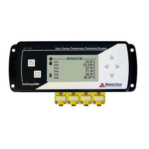
MadgeTech RFRTDTemp2000A Specification sheet

MadgeTech

MadgeTech RFRTDTemp2000A Specification sheet

MadgeTech RFCurrent2000A Specification sheet

MadgeTech

MadgeTech RFCurrent2000A Specification sheet

MadgeTech Pulse101A User manual

MadgeTech

MadgeTech Pulse101A User manual

MadgeTech RFRTDTemp2000A Specification sheet

MadgeTech

MadgeTech RFRTDTemp2000A Specification sheet

MadgeTech RFOT Specification sheet

MadgeTech

MadgeTech RFOT Specification sheet

MadgeTech CTL2000 User manual

MadgeTech

MadgeTech CTL2000 User manual

MadgeTech Shock101-EB Specification sheet

MadgeTech

MadgeTech Shock101-EB Specification sheet

MadgeTech DHS User manual

MadgeTech

MadgeTech DHS User manual

MadgeTech AVS140-6 Specification sheet

MadgeTech

MadgeTech AVS140-6 Specification sheet

MadgeTech Bridge120 User manual

MadgeTech

MadgeTech Bridge120 User manual

MadgeTech Therm-A-lert Specification sheet

MadgeTech

MadgeTech Therm-A-lert Specification sheet

MadgeTech PRTemp1000IS Specification sheet

MadgeTech

MadgeTech PRTemp1000IS Specification sheet

MadgeTech HiTemp140-5.25-TD Specification sheet

MadgeTech

MadgeTech HiTemp140-5.25-TD Specification sheet

MadgeTech Temp1000IS Specification sheet

MadgeTech

MadgeTech Temp1000IS Specification sheet

MadgeTech HiTemp140-FPST-36 User manual

MadgeTech

MadgeTech HiTemp140-FPST-36 User manual

MadgeTech X Series Specification sheet

MadgeTech

MadgeTech X Series Specification sheet

MadgeTech EggTemp-RH User manual

MadgeTech

MadgeTech EggTemp-RH User manual

MadgeTech Temp1000S User manual

MadgeTech

MadgeTech Temp1000S User manual

MadgeTech RFVolt2000A User manual

MadgeTech

MadgeTech RFVolt2000A User manual

Popular Data Logger manuals by other brands

UGCS SkyHub user manual

UGCS

UGCS SkyHub user manual

Avisaro 4.0 Series user manual

Avisaro

Avisaro 4.0 Series user manual

DDB C3 manual

DDB

DDB C3 manual

TESTO 176 instruction manual

TESTO

TESTO 176 instruction manual

HBM SOMAT XR CX22B-R operating manual

HBM

HBM SOMAT XR CX22B-R operating manual

Agtrix 380i manual

Agtrix

Agtrix 380i manual

Beijing ART Tech PCI2320 user manual

Beijing ART Tech

Beijing ART Tech PCI2320 user manual

Athena GET SL1 user manual

Athena

Athena GET SL1 user manual

Motec Systems C185 user manual

Motec Systems

Motec Systems C185 user manual

Beijing ART Tech USB2832 user manual

Beijing ART Tech

Beijing ART Tech USB2832 user manual

HT Italia XL421 user manual

HT Italia

HT Italia XL421 user manual

Racelogic VBOX LapTimer quick start guide

Racelogic

Racelogic VBOX LapTimer quick start guide

Edu-Logger 900-240 Guide

Edu-Logger

Edu-Logger 900-240 Guide

Elma DT173 manual

Elma

Elma DT173 manual

Comet U0121M user guide

Comet

Comet U0121M user guide

pico Technology PT-104 user guide

pico Technology

pico Technology PT-104 user guide

Sensus DIAVASO user manual

Sensus

Sensus DIAVASO user manual

Soil Instruments GTecLink user manual

Soil Instruments

Soil Instruments GTecLink user manual

manuals.online logo
manuals.online logoBrands
  • About & Mission
  • Contact us
  • Privacy Policy
  • Terms and Conditions

Copyright 2025 Manuals.Online. All Rights Reserved.

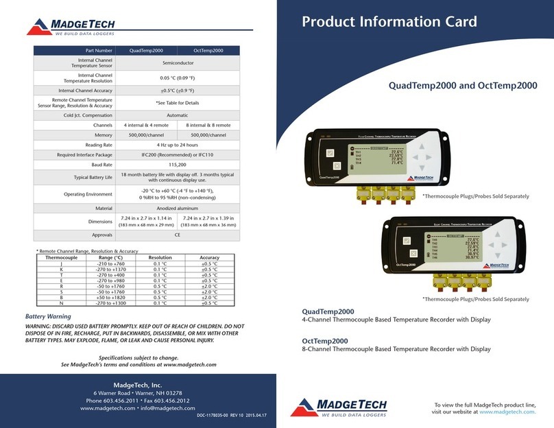
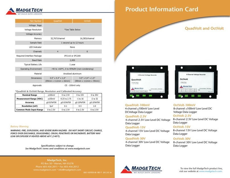
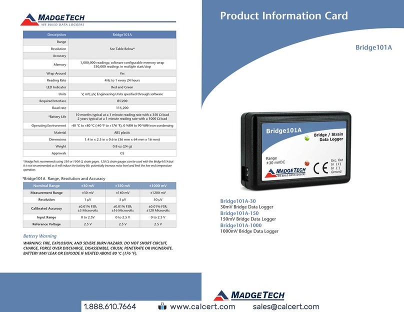
Bridge101A
Red 485
Dark Blue Pantone 289
Light Blue 58% of Pantone 289
*Bridge101A Range, Resolution and Accuracy
Nominal Range ±30 mV ±150 mV ±1000 mV
Measurement Range ±30 mV ±160 mV ±1200 mV
Resolution 1 µV 5 µV 50 µV
Calibrated Accuracy ±0.01% FSR;
±3 Microvolts
±0.01% FSR;
±16 Microvolts
±0.01% FSR;
±120 Microvolts
Input Range 0 to 2.5V 0 to 2.5 V 0 to 2.5 V
Reference Voltage 2.5 V 2.5 V 2.5 V
Battery Warning
WARNING: FIRE, EXPLOSION, AND SEVERE BURN HAZARD. DO NOT SHORT CIRCUIT,
CHARGE, FORCE OVER DISCHARGE, DISASSEMBLE, CRUSH, PENETRATE OR INCINERATE.
BATTERY MAY LEAK OR EXPLODE IF HEATED ABOVE 80°C (176°F).
Specifications subject to change.
REV 13 2014.01.02
Bridge101A-30
30mV Bridge Data Logger
Bridge101A-150
150mV Bridge Data Logger
Bridge101A-1000
1000mV Bridge Data Logger
Description Bridge101A
Range
See Table Below*Resolution
Accuracy
Memory 1,000,000 readings; software congurable memory wrap
330,000 readings in multiple start/stop
Wrap Around Yes
Sample Rate 4Hz to 1 every 24 hours
LED Indicator Red and Green
Units V, mV,
µ
V, Engineering Units specied through software
Reg. Interface IFC200
Baud rate 115,200
Battery Life 10 months typical at a 1 minute reading rate with a 350Ω load
2 years typical at a 1 minute reading rate with a 1000Ω load
Operating
Environment
-40ºC to +80ºC (-40ºF to +176ºF),
0%RH to 90%RH non-condensing
Material ABS plastic
Dimensions 1.4” x 2.5” x 0.6” (36mm x 64mm x 16mm)
Weight 0.8 oz (24 g)
Approvals CE
Product Information Card
www. .com information@itm.com1.800.561.8187
Product Quick Reference Card
Bridge101A
Product Notes
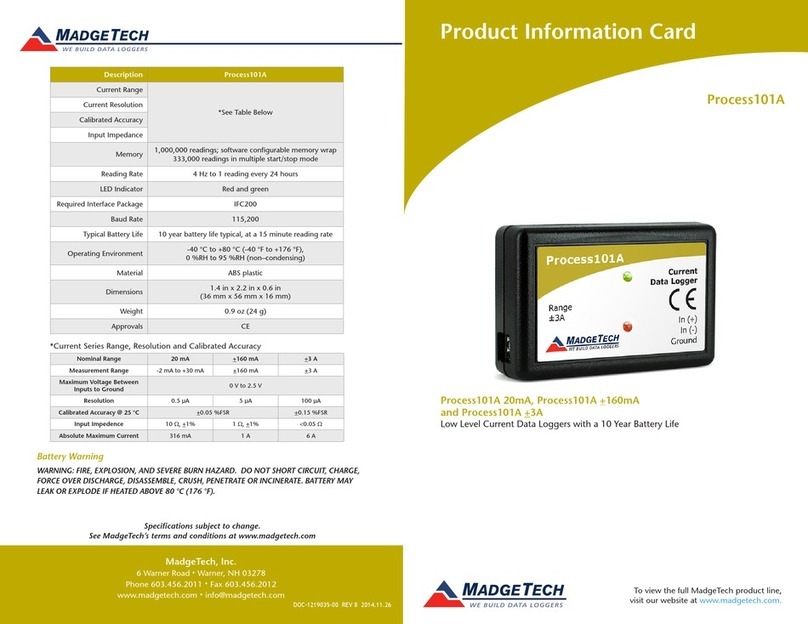
The Bridge101A data logger is designed to interface with and measure strain gauges and load
cells. The device provides an excitation voltage of 2.5V’s and is available in the following
millivolt input ranges: ±30mV, ±150mV, ±1000mV.
LEDs
- Green LED: every 10 seconds to indicate logging and 15 seconds to indicate delay
start mode.
- Red LED: every 10 seconds to indicate low battery and/or memory and 1 seconds to
indicate an alarm condition.
Installation Guide
Installing the Interface cable
- IFC200
Insert the device into a USB port. The drivers will install automatically.
Installing the software
Insert the Software USB Stick in an open USB port. If the autorun does not appear, locate
the drive on the computer and double click on Autorun.exe. Follow the instructions
provided in the Wizard.
Device Operation
Connecting and Starting the data logger
- Once the software is installed and running, plug the interface cable into the data logger.
- Connect the USB end of the interface cable into an open USB port on the computer.
- The device will appear in the Connected Devices list, highlight the desired data logger.
- For most applications, select “Custom Start” from the menu bar and choose the desired
start method, reading rate and other parameters appropriate for the data logging
application and click “Start”. (“Quick Start” applies the most recent custom start options,
“Batch Start” is used for managing multiple loggers at once, “Real Time Start” stores the
dataset as it records while connected to the logger.)
- The status of the device will change to “Running”, “Waiting to Start” or “Waiting to
Manual Start”, depending upon your start method.
- Disconnect the data logger from the interface cable and place it in the environment to
measure.
Note: The device will stop recording data when the end of memory is reached or the device is stopped. At this
point the device cannot be restarted until it has been re-armed by the computer.
Downloading data from a data logger
- Connect the logger to the interface cable.
- Highlight the data logger in the Connected Devices list. Click “Stop” on the menu bar.
- Once the data logger is stopped, with the logger highlighted, click “Download”. You will
be prompted to name your report.
- Downloading will offload and save all the recorded data to the PC.
Device Maintenance
Battery Replacement
Materials: Small Phillips Head Screwdriver and a Replacement Battery (LTC-7PN)
- Puncture the center of the back label with the screw driver and unscrew the enclosure.
- Remove the battery by pulling it perpendicular to the circuit board.
- Insert the new battery into the terminals and verify it is secure.
- Screw the enclosure back together securely.
Recalibration
Bridge101A standard calibration values:
Logger Voltage 30mV 150mV 1000mV
Strain (V) 0V and
22.5-25mV
0V and
90-100mV
0V and
900-1000mV
www. .com information@itm.com1.800.561.8187