SEA CORONA S Instruction manual

up to 2,3 H x 3 L mup to 2,3 H x 3 L m CORONA 60CORONA 60
up to 2,3 H x 4 L mup to 2,3 H x 4 L m CORONA 110CORONA 110
up to 2,7 H x 3 L mup to 2,7 H x 3 L m CORONA 60CORONA 60
up to 2,7 H x 4 L mup to 2,7 H x 4 L m CORONA 110CORONA 110
MAX DOORMAX DOOR
DIMENSIONSDIMENSIONS
up to 2,4 H x 3,5 L mup to 2,4 H x 3,5 L m CORONA 60CORONA 60
up to 2,4 H x 5 L mup to 2,4 H x 5 L m CORONA 110CORONA 110
OPERATORS FOR BALANCED OVERHEAD DOORS WITH SPRINGS
OPERATORS FOR COUNTERBALANCED OVERHEAD DOORS
OPERATORS FOR SECTIONAL GARAGE DOORS
FITTING AND CONNECTION INSTRUCTIONS
Corona S is a non quick grafting operator with aluminium guide.
Corona RP is a quick grafting operator with steel guide.
Corona S/RP is a ceiling actuator easy to install and noiseless
thanks to the slowdown in the last phases of opening and closing.
It is provided with an electronic speed control which allows the
mechanical parts subjected to stress to be saved.
The anticrushing safety is assured by an electronic system
which, set during installation, stops the door in opening and
reverses during closing phase.
Corona S/RP irreversibility avoids the use of electro-locks while
guaranteeing maximum security during forcing attempts.
A Manual Release ensures door operation also in case of power
failure.
ENGLISH
MAIN PARTS OF THE CORONA S OPERATOR
MAX DOORMAX DOOR
DIMENSIONSDIMENSIONS
MAX DOORMAX DOOR
DIMENSIONSDIMENSIONS
Sistemi Elettronici
di Apertura Porte e Cancelli
International registered trademark n. 804888
®
CORONA 60 CORONA 110 CORONA 60 110V CORONA 110 110V
230 V (±5%) 50/60 H 110 V (±5%) 50/60 H
24 V
140 W 370W 140 W 370W
adjustable
60% 40% 60% 40%
-20°C + 60°C
13 kg 14 kg 13 kg 14 kg
600 1100 600 1100
600 1100 600 1100
IP 20
electronic
Miicro switch
TECHNICAL DATA
Power Supply
Motor Supply
Power
Opening Speed
Frequency of use
Operating temperature
Weight
Max Pushing (N)
Max Traction (N)
Protection degree
Anticrushing clutch
Limit switch
Note: The frequency of use is valid only for the first hour at an
outside temperature of 20°C .
CORONA S/RP
Fig. 1
140
20
5
385
Fig. 2
DIMENSIONS (mm)
67410622 Rev 00 - 02/2012 11

Fig. 4
2500 Max Running
150
150
A
A
B
B
B
ENGLISH
Sistemi Elettronici
di Apertura Porte e Cancelli
International registered trademark n. 804888
®
Fig. 6
Fig. 5
Fig. 3
3310
200150385
CORONA S/RP
67410622 Rev 00 - 02/2012
12
Before installing, make sure that the door is perfectly working and that the guide is free of obstacles.
1. CORONA S INSTALLATION
- Connect the aluminium profiles using the two connecting profiles.
- Insert the connecting profile into the aluminium profile for half its length (150 mm) and fix it with the Ascrew. (Fig. 4)
- Repeat for the other two aluminium profiles.
- Insert the two supplied screws (B) into the holes of the aluminium profiles (Fig. 4)
- Connect the two ends of the chain using the connecting link and the two provided screws ( Fig. 5).
- Make sure that the chain has been correctly mounted on the pinion of the Corona S body (Fig. 7 -A).
- Place the guide on the stop of the Corona S body and fix it with the special bracket (Fig. 7 - B).
- Mount the front fixation support on the other end of the guide (Fig. 7 - C)
- Slightly tighten the chain with a 10 key ( Fig.6)
IMPORTANT: Keep well lubricated the chain and the sliding device (Fig. 7 - D).
Note: In Fig.4 a pair of screws are inserted into the loopholes which will be used for fixing the Corona S operator to the ceiling with
the special brackets (See also Fig. 7).
Connecting
Profile
Connecting
Profile
Aluminium
Profile
Aluminium
Profile
Aluminium
Profile

2. CORONA S FIXING
ENGLISH
Sistemi Elettronici
di Apertura Porte e Cancelli
International registered trademark n. 804888
®
Fig. 8
Fig. 9
400 mm Max.
100 mm
Fig. 7
A
C
D
B
CORONA S/RP
67410622 Rev 00 - 02/2012 13
- First of all fix the front part of the
Corona S making sure that it’s placed
iat the centre of the door;
- Fix the anchor bracket to the door
frame or if necessary on the wall using
rivets or bolts (Fig. 8);
- Lift the Corona S and fix it to the ceiling
with the special brackets keeping a
maximum distance of 400 mm from the
ceiling and making sure that the
operator is in a perfectly horizontal
position (Fig. 9);
- Release the Corona S operator and
drag the drawing rod towards the door,
then fix it to the door.

up to 2,3 H x 3 L mup to 2,3 H x 3 L m CORONA 60CORONA 60
up to 2,3 H x 4 L mup to 2,3 H x 4 L m CORONA 110CORONA 110
OPERATORS FOR BALANCED OVERHEAD DOORS WITH SPRINGS
MAX DOORMAX DOOR
DIMENSIONSDIMENSIONS
3. INSTALLATION KIT
FOR GARAGE DOORS
400 mm Max.
30 mm Min.
90°
Fig. 10
Fig. 12 Fig. 13
Fig. 14
1
23
up to 2,7 H x 3 L mup to 2,7 H x 3 L m CORONA 60CORONA 60
up to 2,7 H x 4 L mup to 2,7 H x 4 L m CORONA 110CORONA 110
OPERATORS FOR COUNTERBALANCED OVERHEAD DOORS
MAX DOORMAX DOOR
DIMENSIONSDIMENSIONS
ENGLISH
Sistemi Elettronici
di Apertura Porte e Cancelli
International registered trademark n. 804888
®
Fig. 11
CORONA S/RP
67410622 Rev 00 - 02/2012
14
We recommand to use additional brackets (optional)
Additional brackets

Sistemi Elettronici
di Apertura Porte e Cancelli
International registered trademark n. 804888
®
Fig. 15
CORONA S/RP
Operator 5~10 cm
Fig. 16 Fig. 17
67410622 Rev 00 - 02/2012
Operator
Guide track Bend link lever
Base for pulling Guide track bracket
Link lever
Accessories
Transmitter
MAIN PARTS OF THE AUTOMATION CORONA RP
Guide track Power supply
ENGLISH
15
On request one 4m piece guide
Release
knob
Fixing bracket U-shaped bracket
To adjust the door closing as precise as possible, release the bolts on the curved rod and adjust the run on the two holes (Fig. 15)
CONNECTION OF THE OPERATOR CORONARPWITH THE GUIDE TRACK
Before installing the operator remove all unnecessary ropes or chain and disable any equipment, such as locks, not needed for
powdered operation.
Before installing the operator, check that the door is in good mechanical condition correctly balanced and opens and closes
properly.
U-shaped bracket 1 U-shaped bracket 2
Fixing bracket Sliding block
(Sleigh)

Sistemi Elettronici
di Apertura Porte e Cancelli
International registered trademark n. 804888
®
CORONA S/RP
Fig. 18
Fig. 19 Fig. 20
Fig. 21 Fig. 22
67410622 Rev 00 - 02/2012
Centre line
Wall
Door
ENGLISH
16
5. INSTALLATION OF THE GUIDE ON THE WALL AND ON THE CEILING FOR CORONA RP
Guide
Wood
(Thikness: 25mm, junction in the space
within door and guide)
Sleigh
After having fixed the operator to the hanging firmware, remove the wood.

Fig. 23 Fig. 24 Fig. 25
Sistemi Elettronici
di Apertura Porte e Cancelli
International registered trademark n. 804888
®
CORONA S/RP
67410622 Rev 00 - 02/2012
Fig. 27
Fig. 26
F1
F2
F1= 6.3 AT
F2= 3.15 AT
Base
for
pulling
Bend link
lever
Base for
pulling
Link lever
7. ELECTRONIC CONTROL UNIT
ENGLISH
17
1. Close the door and fix the base for pulling at the center on the top of the door (Fig. 23).
2. Release the sleigh (Fig.24).
Place the sliding block (sleigh) near the door. Connect the base for pulling, the bend link lever, the link lever and the sleigh (Fig.25).
- Install the the manual release at a height of max. 1.8m
- The warning boards against entrapment should be permanently fixed in a known place or near any fixed control.
- The notice concerning the manual release should be permanently fixed next to said release.
After installation, make sure that the mechanism is properly adjusted and that the drive reverses when the door touches a 50 mm
high object placed on the floor.
6. CONNECTION OF THE DOOR WITH THE SLIDING BLOCK (SLEIGH) FOR CORONA RP
For accessing the electronic unit and execute all desired settings, unscrew the two fixing screws (Fig. 26) and open the case as
shown in Fig. 27.
Sleigh

NOTICE
SEA s.r.l can not be deemed responsible for any damage or accident caused
by product breaking, being damages or accidents due to a failure to comply
with the instructions herein. The guarantee will be void and the manufacturer
responsibility (according to Machine Law) will be nullified if SEA Srl original
spare parts are not being used.
This is a
quotation from the GENERAL NOTICE that the installer must read carefully
before installing.
Packaging materials such as plastic bags, foam polystyrene, nails etc must
be kept out of children’s reach as dangers may arise.
The electrical installation shall be carried out by a professional technician
who will release documentation as requested by the laws in force.
Sistemi Elettronici
di Apertura Porte e Cancelli
International registered trademark n. 804888
®
7
6
34
2
1
5
CORONA S/RP
Fig. 28
67410622 Rev 00 - 02/2012
8. TYPICAL INSTALLATION
9. PERIODICAL MAINTENANCE
Verify the smooth sliding of the chain
Verify the tightening of the chain
Verify the stability of the ceiling and
door junctions
Verify the door is in a good state and
that the slides are not dirty
Verify the tension of the steel cable of
the external release
Verify the general condition of the operator
(transformer, motor, electronic control unit)
Keep the chain and the sliding support
lubricated
Semestral
Semestral
Semestral
Annual
Annual
Annual
Semestral
All the above described operations must be made
exclusively by an authorized installer.
SAFETY PRECAUTIONS:
All electrical work should conform to current regulations. A 16 A 0,030 A differential switch must be incorporated into the source of the operators
main electrical supply and the entire system properly earth bonded. Always run mains carrying cables in separate ducts to low voltage control
cables to prevent mains interference.
INTENDED USE:
The CORONAS/RPoperator has been designed to be solely used for the automation of sectional doors and balancing doors.
SPARE PARTS:
To obtain spare parts contact: SEAs.r.l. -Zona Ind.le, 64020 S.ATTO Teramo Italia
SAFETYAND ENVIRONMENTAL COMPATIBILITY:
Don’t waste product packing materials and/or circuits.
When being transported this product must be properly packaged and handled with care.
CORRECT DISPOSAL OF THIS PRODUCT (WASTE ELECTRICAL& ELECTRONIC EQUIPMENT) - EUROPE ONLY
(Applicable in the European Union and other European countries with separate collection systems)
This marking shown on the product or its literature, indicates that it should not be disposed with other household wastes at the end of its
working life. To prevent possible harm to the environment or human health from uncontrolled waste disposal, please separate this from
other types of wastes and recycle it responsibly to promote the sustainable reuse of material resources.
Household users should contact either the retailer where they purchased this product, or their local government office, for details of where
and how they can take this item for environmentally safe recycling.
LIMIT OF GUARANTEE
For the guarantee see the sales conditions on the official SEA price list.
MAINTENANCE AND OUT OF SERVICE:
The decommission and maintenance of this unit must only be carried out by specialised and authorised personnel.
NOTE: THE MANUFACTURER CAN NOT BE DEEMED RESPONSIBLE FOR ANY DAMAGE OR INJURY CAUSED BY IMPROPER USE OF
THIS PRODUCT.
SEA reserves the right to do changes or variations that may be necessary to its products with no obligation to notice.
ENGLISH
18
1) CORONA S/RP operator
2) On board receiver
3) Left photocell
4) Right photocell
5) Start-Stop button
6) Safety box for external release
7) Warning lamp

10. STRING RELEASE SYSTEM FOR CORONA S
AND CORONA RP
To release the operator, work as follows:
- Pull the release knob and open the door manually (Fig. 29).
11. HANDLE RELEASE SYSTEM FOR CORONA S
To release the operator, work as follows:
- Turn the knob and open the door manually
(Fig. 30)
Notice: This release system allows the external
releasing of the door
Fig. 29
ENGLISH
Sistemi Elettronici
di Apertura Porte e Cancelli
International registered trademark n. 804888
®
19
Fig. 30
To the attention of users and technicians
CORONA S/RP
67410622 Rev 00 - 02/2012
This manual suits for next models
5
Table of contents
Other SEA Controllers manuals
Popular Controllers manuals by other brands
SMC Networks
SMC Networks PSE200 Series Operation manual
TQ
TQ TQMxE40C1 user manual

Mitsubishi Electric
Mitsubishi Electric MELSEC Q Series user manual
Marathon Electric
Marathon Electric DVR 2000E+ user manual
ZyXEL Communications
ZyXEL Communications NXC5500 quick start guide
Tecomotive
Tecomotive tinyCWA user manual
Infineon
Infineon IMC300A Series Getting started guide
CPC
CPC MultiFlex RTU Installation and operation manual

Sanyo
Sanyo VSP-3000 Service manual
Honeywell
Honeywell FAST-ACTING, TWO-POSITION ACTUATORS ML4202 installation instructions
Inventronics
Inventronics DALI PRO CONT-4 RTC manual
Chamberlain
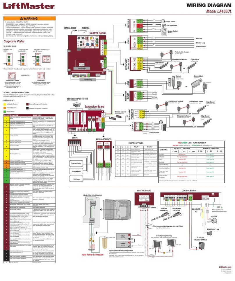
Chamberlain LA400UL Wiring diagram

