SEA E-SUN PLUS BOOST User manual

E-SUN PLUS BOOST
SOLAR MPPT CHARGE CONTROLLER
Manuale utente
User manual
Manuel de l’utilisateur
Manual del usuario
Benutzerhandbuch
IT
DE
ES
EN
FR
67410218 - Rev. 00 - 08/22

EN
1
ESUN PLUS BOOST has got a buck-boost charge circuit with control of the
maximum power point of the PV module (MPPT). The main difference
between this controller and other types with buck circuit is that ESUN
PLUS BOOST is able to allow the working of the PV module at a voltage than
can be either higher or lower than that of battery; this allows, for example, to
use a PV module with open circuit voltage of 10V for the charge of batteries
both at 12V and 24V. PV module voltage during the working of MPPT circuit
goes from 5V to 40V with both 12V and 24V batteries.
ESUN PLUS BOOST is a complete solution for the realization of off-grid PV
systems, to power supply road signs systems, lighting systems, small low
voltage systems and for the charge of batteries inside
caravans and boats. The several programs of load management,
selectable by the user, make ESUN PLUS BOOST the proper solution in
several applications; i.e. to power supply video cameras that have to
work only during the day, or to power supply flashing systems/road signs
that have to work only during night or to power supply lighting systems
that have to work only for a certain number of hours during night. ESUN
PLUS BOOST detects the day/night status according to the PV module’s
voltage; therefore, it is not necessary to connect further sensors to the
controller. A wide display shows the working status of the charge
controller either through simple and intuitive icons or displaying the values
of charge current, battery voltage, energy produced by the PV module,
load current and energy consumed by the load.
MPPT charge with buck-boost
circuit
Max PV module power:
120W for 12V battery
220W for 24V battery
Integrated blocking diode
For sealed, GEL or flooded lead
acid batteries and and lithium-
ion batteries
Temperature compensated
Charge voltage
Auto-detect of battery voltage:
12V / 24V
18 programs for load
management
LCD for user interface
IP20 metal box
•Low battery protection
•Over temperature protection
•Protection for battery polarity
inversion
•Overload protection on output

EN
2
General safety Instructions
Danger, electric shock Danger, hot surface
•It is mandatory to read this manual carefully before installing or using the product.
•If the product is not installed and used as described in this manual the product cannot be considered
safe, so it could damage people or animals.
Installation and maintenance:
•The product must be installed only by qualified personnel.
•Make sure that the batteries in use are compatible with the product by checking the battery type, the
nominal voltage and the charging voltage on their data sheet.
•Make sure that the battery room is properly ventilated as indicated in the battery installation manual.
•When connecting the battery, sparks can occur which can damage the operator's retina.
•When the photovoltaic module is exposed to the sun it generates voltage. If the panel has voltage
Voc> 50V it is mandatory to use isolating gloves to protect the installer from electric shock.
•For battery maintenance refer to the battery maintenance manual.
•The product cannot be repaired by the user or by the personnel performing the installation; it must
not therefore be opened or left working with the panel open.
•Do not install the product in a place where gas or dust explosions may occur.
•Protect cables with suitable fuses from the short-circuit, in particular it is mandatory to place a fuse of
adequate current on the battery cable as close as possible to the positive battery terminal.
Warranty
The defective product must be returned to SEA S.p.A. for assistance, at the expense of the customer, along with a copy of
the sales invoice, both for repairing and guaranteed replacement. The costs of re-installation of the material will be borne
by the customer. Warranty does not cover Products that, according to our discretion, are defective owing to natural
wear, have failures caused by malpractice or negligence of the customer, by incorrect installation, by tampering or
interventions that are different from the instructions supplied by us. Warranty is void if damage is also caused by:
- transport and/or bad storage of the product.
- force majeure or catastrophic events (frost for temperatures < -20°C, fire, flooding, lightning, vandalism, and so on).
All the above guarantees are the sole and exclusive agreement which supersedes any proposal or agreement whether
written or oral and any other communication made between the producer and the purchaser with respect to the above.
For any dispute the jurisdiction is Teramo (Italy).
Disposal of waste
SEA S.p.A., in accordance with Law No. 151 25/07/05, informs the buyer that this product, once
divested, must be delivered to an authorized recycling center or, in case of purchase of equivalent
equipment, it may be returned at no cost to the distributor of the new equipment. Penalties for those
who get rid of an electronic waste will be used by individual municipalities.

EN
3
General description
ESUN PLUS BOOST is a photovoltaic charge controller for leaden electrochemical batteries either sealed (SEAL) or
flooded lead acid (FLOOD) or lithium ions or LiFePO4. In Pic.1 there is a scheme principle of ESUN PLUS BOOST. It is
absolutely forbidden connect to ESUN PLUS BOOST lithium-ion batteries without a BMS; the BMS protect the battery
from unsafe operating condition that can to lead battery to explosion or to burn up.
Pic.1 Principle diagram
1- Charge circuit: it adapts Vpan and Ipan (respectively voltage and current of the PV module) so to search the
condition in which the power that is given by the PV module is maximum, thus realizing the MPPT (Maximum Power
Point Tracking). In addition, it manages the battery charge by reducing the current sent towards the battery when
the battery Vbatt exceeds its charge voltage (Veoc).
2- Circuit for load control: it turns on/off the load according to the program set by the user and it provides to load
detachment in case of discharged battery, overload or short-circuit on the load.
3- Microprocessor: it controls the whole circuit, it measures currents and voltages of PV module, battery and load and it
shows them on the display.

EN
4
Wiring scheme
PV
MODULE
BATTERY
LOAD
BATTERY TEMPERATURE SENSOR
Minimum distance
>
10 Cm
Recommended pairs of copper wire that guarantee a maximum
voltage drop of 1.5% of the battery nominal voltage.
12V battery nominal voltage
Wire section
2.5
mm2
4
mm2
6
mm2
10
mm2
Max. length
wires couple
[m]
Current
5 A 2.6 4.2 6.3 10.4
10 A 1.3 2.1 3.1 5.2
20 A 0.9 1.4 2.1 3.5
24V battery nominalvoltage
Wire section
2.5
mm2
4
mm2
6
mm2
10
mm2
Max. length
wires couple
[m]
Current
5 A 5.2 8.4 12.5 20.9
10 A 2.6 4.2 6.3 10.4
20 A 1.7 2.8 4.2 7.0
Pic.2 Wiring scheme
1) Install ESUN PLUS BOOST in a dry and adequately ventilated place; it must be fixed on a non-flammable surface and placed
so to leave an unobstructed space of at least 10cm around the device that allows the cooling by natural air convection.
2) Connect respectively: load, sensor for battery temperature measure (supplied), PV module and, last, the battery as in
the scheme Pic.2. When you connect the battery the charge controller turns on and it begins to work.
Use proper cable sections as indicated in Pic.2.
3) ESUN PLUS BOOST recognizes automatically the battery nominal voltage (12V or 24V) and it adapts consequently its
threshworkingolds. The user must configure the kind of battery in use to adequate the right charge voltage (Veoc). You have
to set SEAL configuration if you use VRLA or GEL sealed batteries, while you have to choose FLOOD configuration if you use
flooded lead acid batteries. If you use lithium-ionn (Tab.2).
4) Set the proper load management program to your own application (Tab.2).
Testing
Once made the connections as in Pic.2 it is necessary to proceed with the testing of the system.
1) With the PV module exposed to sunrays, verify that ESUN PLUS BOOST is charging the battery reading the values of charge
current Ipan and Ibatt (see Tab.1).
2) To verify that the battery temperature sensor has been properly connected, check on the LCD that at the page
“battery temperature” a reliable temperature value is displayed (Tab.1).
3) Verify the correct turning on of the load. If the load is ON only during night, it is possible to simulate the night by
disconnecting temporarily one of the wires of the PV module. With load ON, check the absorbed current by reading in
the proper page of LCD (Tab.1).
WARNING!
Do not connect to the
output loads that draw
more than 15A as
inverters.

EN
5
Visualizations
Day/night status
Only displayed in the configuration screens Low battery protection
Load turning on
It indicates which charge
program is currently set It displays internal measures
Voltage level inside the
battery
Indication of current
absorption on the load
Indication of current
absorption from the
PV module
Main page.
It displays the battery voltage (Vbatt), the charge program currently selected (either SEAL or
FLOOD), the day/night status detected by the PV module. The load icon, if ON, indicates that the
load is power supplied.
button
It displays the current (Ipan) of the PV module. We remember that the current delivered by the
PV module depends on its state of sun-lighting and on battery charge status. With charged battery
(Vbatt>14,4V @12V o Vbatt>28,8V @24V) and even with a good lighting of the PV module, you
have low charge currents since the controller limits such current so to avoid the battery
overcharge.
button
PV module voltage (Vpan).
button
It displays the power in watt actually delivered by the PV module.
button
It displays the counter of energy that is delivered by the PV module in KWh. It is possible to reset
this measure pressing simultaneously the buttons for 2 seconds.
button
It displays the charge current inside the battery (Ibatt).
button
It displays the battery temperature that is currently measured by the temperature
sensor connected to ESUN PLUS BOOST.
button
It displays the current that is currently delivered to the load; even if in this screen the load icon is
on, this does not mean that it is effectively power supplied; in fact, the load is controlled
according to the management load program that is currently set.
button
It displays the power that is currently delivered to the load in watt.
button

EN
6
It displays the Energy counter in KWh consumed by the load. It is possible to reset this counter
pressing simultaneously the buttons for 2 seconds.
button Pressing the button you go back to the main page.
Tab.1 Display pages of measures
.
System configuration
You can go to the configuration pages of ESUN PLUS BOOST pressing simultaneously for at least 2 s the buttons
Charge program configuration page
….
It sets the charge voltage for the battery.
SEAL must be set for sealed VRLA or GEL lead acid batteries (*).
FLOOD must be set for flood lead acid batteries (*).
Li must be set for charge lithium-ion batteries. In this case you must also configure the
exact charge voltage so that it is in accordance with charge voltage in the datasheet of
the battery manufacturer. In the ESUN PLUS BOOST you can set lithium-ion battery
charge voltage in the range:
14.0V – 14.7V for 12V systems,
28.0V – 29.4V for 24V systems
When lithium-ion program is activated, the charge voltage is not compensated in
accordance with temperature as in SEAL, FLOOD and programs, but the charge voltage is
equal for every temperature measured.
(*) Charge voltage relating to each one of the programs are indicated in the following
Pic.3, Tab.4 and must be chosen in accordance with the battery manufacturer indications.
Page change
Low Battery voltage configuration page
It sets the intervention voltage of Low Battery protection (load detachment in case of low
battery). When pressing the button you change the setting from 10.8V to 12.2V for
12V systems and from 21.6V to 24.4V for 24V systems.
Page change
Exit low battery voltage configuration page
It sets exit low battery threshold voltage. With button you will modify the threshold in
the range from 12.4V to 13.8V for 12V systems, and from 24.8V to 27.6V for 24V systems.
Page change
Load management program configuration page
…
Load always ON either
during day or during
night.
Load ON only
during day.
Load ON only
during night.
Load ON during
night for 1
hour.
Load ON during night for
16 hours.
Page change
Voltage detection day
ESUN PLUS BOOST detects the day when the voltage of PV module (Vpan) is > than
the Vday threshold; it detects the night when Vpan is < than Vnight threshold. In
this page it is possible to change Vday threshold. Vnight threshold = Vday – 0.8V
Page change

EN
7
Float Voltage
You can set Float Voltage (Vflt at 25°C). When battery voltage is equal to charge voltage
(Veoc) for Tabs time, ESUNPB enters in float state, where battery voltage is set to
Vflt. Float Voltage is temperature compensate (-24mV/°C at 12V and -48mV/°C at 24V).
Page change
Absorption time
You can set Absorption time in hours (Tabs). When battery voltage is in Veoc livel for
Absorption time, the ESUN PB starts float state, where battery voltage is set to Vflt.
Page change
Software version display page
It displays the software version in use on ESUN PLUS BOOST. This manual refers to
software version 1.2.
You go back to the configuration page of the recharge program.
Tab.2 Setting pages
Once modified the settings of ESUN PLUS BOOST these become operative only after the exiting from the
configuration pages pressing simultaneously for at least 2 seconds the buttons .
Error and warnings codes
With the intervention of del ESUN PLUS BOOST internal protections, there are the below reported error codes.
Table of Error code
The battery was connected with
inverted polarities. Check the
electrical connections of the battery.
You have this error when internal
temperature of ESUN PLUS BOOST exceeds
80°C and deactivates the charge. You exit
automatically from this protection when the
internal temperature goes below the
threshold of 50°C (note: the internal
temperature of the charge controller is not
displayed on the LCD). If you see often this
protection we advise to place the device in a
cooler place.
Overload protection occurred. The
load current exceeded the maximum
allowed limit for ESUN P.B. (Iload in the
“Table of electrical features”) and the
device detached the load to prevent
internal damages. If there is such a
signalling, it is necessary to check if the
current absorbed by the load is < than
the allowed limit. After 1 minute ESUN
PLUS BOOST tries to power supply again
the load. It exits from this condition if
the cause that generated the overload
has been eliminated
You have this error when the battery voltage
is < than 9.0V. In these conditions, the
charge is disabled.
Warnings
When low battery symbol is flashing this indicates that there is the low battery protection - load has
been disconnected to preserve battery life. This protection intervenes when the battery voltage goes
under VLB threshold that can be set by the user (Tab.2). ESUN PLUS BOOST leaves this protection when
the battery will be charged by the PV module at Velb voltage (settable).
Tab.3 Table of error codes

EN
8
Graphics
End-charge voltage according to temperature - 12V system
13,5
14,0
14,5
15,0
15,5
16,0
-10 -5 0510 15 20 25 30 35 40 45 50 55 60
Temperature °C
End-charge voltage - Volt
SEAL FLOOD
End-charge voltage according to temperature - 24V system
27,0
27,5
28,0
28,5
29,0
29,5
30,0
30,5
31,0
31,5
32,0
-10 -5 0510 15 20 25 30 35 40 45 50 55 60
Temperature °C
End-charge voltage - Volt
SEAL FLOOD
Pic.3 Compensation curve of Veoc charge voltage according to battery temperature
Dimensions
Pic.4 Dimensions

EN
9
Electrical Features
12V battery nominal voltage 24V battery nominal voltage
Min Typ Max Min Typ Max
Battery voltage Vbatt 10V 16V 20V 32V
Open circuit voltage of PV module Vpan 5V - 40V 5V - 40V
PV module current IPan - - 10A - - 10A
Max PV module power Pmax - - 120W - - 220W
Load output voltage Vload - Battery voltage - - Battery voltage -
Load current Iload - - 15A - - 15A
Recharge voltage at 25°C - SEAL program
(default) Veoc 14.4V 28.8V
Recharge voltage at 25°C - FLOOD program Veoc 14.8V 29.6V
Recharge voltage at 25°C – Li program(*) Veoc 14.0V - 14.7V 28.0V - 29.4V
Veoc compensation according to battery
temperature (Tbatt) Vtadj - -24mV/°C - - -48mV/°C -
Low battery voltage (settable) Velb 10.8V 11.4V
(default) 12.2V 21.6V 22.8V
(default) 24.4V
Output voltage from low battery (settable) Velb 12.4V 13.8V
(default) 13.8V 24.8V 27.6V
(default) 27.6V
Solar modules threshold voltage for day
detection (settable) Vday 12.4V 13.8V
(default) 13.8V 24.8V 27.6V
(default) 27.6V
Solar modules threshold voltage for night
detection:
Vnight = Vday –1.3V
Vnight 0.6V - 8.3V 0.6V - 8.3V
Float phase voltage (settable) Vflt 13.2V - 14.4V 26.4V - 28.8V
Absorption phase time (settable) Tabs 1h 3h (default) 8h 1h 3h (default) 8h
Self-consumption Iq 12.7mA
(Vbat 14,0V)
17,7mA
(Vbat 28,0V)
Operating Temperature Tamb -40°C 50°C -40°C 50°C
Dissipated power Ploss 20 W 29 W
Terminals section 1mm2 10mm2 1mm2 10mm2
IP protection degree IP20 IP20
Weight - 515 g - - 515 g -
Tab.4 Table of electrical features
(*) When you set Li charge program the charge voltage is constant versus battery temperature.

NOTES
________________________________________________________
________________________________________________________
________________________________________________________
________________________________________________________
________________________________________________________
________________________________________________________
________________________________________________________
________________________________________________________
________________________________________________________
________________________________________________________
________________________________________________________
________________________________________________________
________________________________________________________
________________________________________________________
________________________________________________________

Table of contents
Other SEA Controllers manuals
Popular Controllers manuals by other brands
RealSimulator
RealSimulator FSSB-R3 Lighting user guide
nekos
nekos SKYRO 850 instruction manual
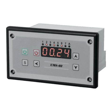
MAKOT
MAKOT UMS-02 user manual

SMSC
SMSC USB2242 datasheet
Mitsubishi Electric
Mitsubishi Electric MELSEC iQ-F FX6U Hardware user manual

Chemitech IT Perdana
Chemitech IT Perdana pH/ORP-3500 Series Operation manual


