SeaBotix Generation 2 Reference guide

Generation 2
Service & Maintenance Procedures Manual

The information, photographs, illustrations and descriptions contained in this procedures
manual are the property of SeaBotix Inc. Unauthorized duplication and distribution is
strictly forbidden. Additionally, SeaBotix Inc. reserves the right to alter any and all
information contained in this procedures manual.
Potential Hazards
LBV is a safe and reliable tool when used and cared for properly. However, certain
hazards do exist and should be carefully observed.
Thruster Propellers
ßKeep propellers clear of obstructions.
ßDo not put fingers near propeller at any time.
ßBe careful with loose clothing.
Electrical Shock
ßLBV operates on high voltages that can cause injury and or death.
ßKeep Surface Power Supply plug away from water.
ßCheck all plugs for water prior to connecting.
ßIf umbilical is cut do not operate LBV.
ßDo not open LBV when power is on.
Purpose of this Procedures Manual
The purpose of this procedures manual is to provide LBV operators with necessary
information to repair LBV. If any part of the procedures is unclear contact SeaBotix Inc.
or an authorized distributor for more detailed information.
Liability
SeaBotix Inc. shall not be held liable for improper procedures resulting in damages,
injuries or losses as a result of the improper following of procedures. Additionally,
SeaBotix Inc. shall not be held liable for any damages, injuries, losses or problems
associated with a LBV system that has been modified without written consent from
SeaBotix Inc.
How to use this procedures manual
This manual should be thoroughly reviewed prior to repairing or altering a LBV. When
the necessary repair is determined identify which removal and installation procedures
are required. Ensure the instructions are understood, all tools are present and you are
comfortable with the repair procedure.

Protective Shell & Bumper Frame
Introduction
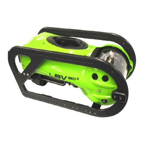
LBV2is fitted with a Protective Shell and Bumper Frame. The purpose of the protective shell is
to protect the internal components as well as provide a more hydrodynamic shape through the
water. In addition, the LBV2systems are fitted with a protective bumper frame offering further
protection, mounting for the ballast weight and various optional accessories.
Work Environment
Prior to beginning ensure you have a clean and dry workspace. Locate the required tools and
parts and have paper towels available. It is a good idea to have a container to keep fasteners
in as they are removed. Read through the instructions fully prior to beginning and make sure
you understand what they are asking you to do.
Reading Manual
Below is a list of the required tools, estimated time to complete and level of difficulty. Next to
each step where a tool is required the tool is listed. Some of the steps have special notes that
must be observed.
Tools Required
•#2 Phillips Screwdriver
•10mm Socket Head Driver
Time to complete
•10 minutes removal
•10 minutes install
Level of Difficulty
•Easy
Prior to working on the LBV make sure the power is off
and the umbilical is DISCONNECTED.

Removal
Step 1
Place the LBV on its starboard side.
Step 2 – Phillips #2 Screwdriver
Remove the 2 M5 x 12 Button head socket screws securing the
crossbar to the starboard bumper frame rail.
Note: there is a washer with each screw.
Step 3 – 10mm Socket Head Driver
Remove the M6 hex nut from the front of the port shell.
Step 4 – Phillips #2 Screwdriver
Remove the M4 x 10 Phillips pan head screw from the rear of
the port shell securing it to the float.
Step 5 – Phillips #2 Screwdriver
Remove the 2 M4 x 20 Phillips pan head screws from the port
shell securing it to the float.
Note: you will have to work in around the bumper frame rail.

Step 6
Lift off the port shell and bumper frame assembly.
Note: be careful not to scratch the view port with the crossbar.
Step 7
Turn the LBV over and place on its port side.
Step 8 – 10mm Socket Head Driver
Repeating a similar process to the port shell remove the 10mm
hex nut at the front of the starboard shell.
Step 9 – Phillips #2 Screwdriver
Remove the M4 x 50 Phillips Pan Head screw from the rear of
the shell.
Note: a gray plastic tube acts as a spacer between the shell and
the float. This spacer will fall out when you remove the screw.
Step 10 – Phillips #2 Screwdriver
Remove the 2 M4 x 20 Phillips pan head screws from the top of
the shell.
Note: again you will have to work around the bumper frame.

Step 11
Lift off the shell and bumper frame assembly then place LBV on
its back.
Removal process complete.
Installation
Step 1
Place the LBV on its port side with the accessory ports up.
Step 2
Take the protective shell and bumper frame assembly and lower
onto the LBV. Line up the forward stud and the under lip of the
shell to the back plane.
Step 3 – Phillips #2 Screwdriver
Insert and tighten 2 M4x20 Phillips pan head screws in top of
shell to float.
Step 4 – 10mm Socket Head Driver
Screw on M6 hex nut to threaded stud and tighten.

Step 5 – Phillips #2 Screwdriver
Insert the M4 x 50 Phillips pan head screw into the rear of the
shell. Guide the screw through the gray plastic spacer and
tighten into the float insert.
Step 6
Turn the LBV over onto its starboard side.
Step 7
Lower the port shell and bumper frame assembly onto the LBV
aligning the forward threaded stud and lip under the shell to
back plane as you did with the starboard shell.
Note: be careful not to scratch the view port with the center
crossbar.
Step 8 – Phillips #2 Screwdriver
Insert and tighten 2 M4x20 Phillips pan head screws into the top
of the shell.
Step 9 – 10mm Socket Head Driver
Screw on the 10mm hex nut onto the threaded stud at the front
of the shell.

Step 10 – Phillips #2 Screwdriver
Insert and tighten the M4 x 10 Phillips pan head screw into the
rear of the shell.
Step 11 – Phillips #2 Screwdriver
Insert and tighten the 2 M5 x 12 button head screws securing
the crossbar to the port bumper frame rail.
Note: careful not to over tighten.
Procedure Complete

Flotation Module
Introduction
Providing buoyancy for the LBV2is the flotation module. The flotation module is located
behind the protective shell. Mounting points for the shell are located on the flotation module as
well as the front camera housing. The flotation module mounts directly to the back plane.
Work Environment
Prior to beginning ensure you have a clean and dry workspace. Locate the required tools and
parts and have paper towels available. It is a good idea to have a container to keep fasteners
in as they are removed. Read through the instructions fully prior to beginning and make sure
you understand what they are asking you to do.
Reading Manual
Below is a list of the required tools, estimated time to complete and level of difficulty. Next to
each step where a tool is required the tool is listed. Some of the steps have special notes that
must be observed.
Tools Required
•#2 Phillips Screwdriver
•4mm Hex Ball Driver
Time to complete
•5 minutes removal
•5 minutes install
•20 minutes including
other procedures
Level of Difficulty
•Easy
Prior to working on the LBV make sure the power is off
and the umbilical is DISCONNECTED.

Removal
Prior to performing this procedure you must first follow
these procedures:
•Shell/Bumper frame removal
Step 1
Place the LBV upside down.
Step 2 – Phillips #2 Screwdriver
Remove the 2 M4x6 Phillips pan head screws securing the rear
trim tab to the thruster Kort nozzles.
Step 3 – Phillips #2 Screwdriver
Remove the 3 Phillips pan head screws securing the lateral
thruster Kort nozzle to the lateral thruster. Remove Kort nozzle.
Step 4 – Phillips #2 Screwdriver
Remove the 2 M4x10 Phillips pan head screws at the rear of the
flotation module.

Step 5 – Phillips #2 Screwdriver
Remove the 2 M4x10 Phillips pan head screws located in the
middle of the flotation module near the vertical thruster elbow.
Step 6 – 4mm Hex Ball Driver
Remove the 2 M6x16 button head cap screws at the front of the
float securing the camera housing end caps and flotation
module.
Step 7
Holding the back plane with one hand raise the LBV allowing
the flotation module to drop. Remove the flotation module.
Installation
Step 1
Just as the flotation module was removed lift the LBV up to
allow the flotation module to be centered under the LBV. Align
the vertical thruster in the Kort nozzle pressed into the flotation
module.
Step 2 – Phillips #2 Screwdriver
Insert and tighten SLIGHTY the 2 M4x10 Phillips pan head
screws in the middle of the flotation module. This helps to align
the flotation module for the other screws.

Step 3 – Phillips #2 Screwdriver
Insert and tighten the M6x16 button head cap screws into the
forward part of the flotation module.
Note: make sure the nylon washers are on the screws prior to
installing.
Step 4 – Phillips #2 Screwdriver
Insert and tighten the 2 M4x10 Phillips pan head screws located
at the rear of the float.
Note: you might have to push the rear part of the float to align
the holes.
Step 5 – Phillips #2 Screwdriver
Tighten the 2 M4x10 Phillips pan head screws at the middle of
the flotation module.
Step 6
Push Kort nozzle onto lateral thruster aligning all three legs.
Insert and tight the Phillips pan head screws.
Note: be careful not to over tighten and strip the threads.
Step 7
Insert and tighten the 2 M4x6 Phillips pan head screws securing
the rear trim tab to the thruster Kort nozzles.
Note: be very careful not to over tighten as you will strip out the
threads.

Once complete follow the procedures to:
•Install Shell/Bumper Frame

Vertical Thruster
Introduction
The LBV2is fitted with four (4) identical thrusters. They can be interchanged to any position.
Each thruster is isolated from the main housing and other thrusters. They have a four (4) pin
connector for power and data. There is an o-ring seal around the connector.
Work Environment
Prior to beginning ensure you have a clean and dry workspace. Locate the required tools and
parts and have paper towels available. It is a good idea to have a container to keep fasteners
in as they are removed. Read through the instructions fully prior to beginning and make sure
you understand what they are asking you to do.
Reading Manual
Below is a list of the required tools, estimated time to complete and level of difficulty. Next to
each step where a tool is required the tool is listed. Some of the steps have special notes that
must be observed.
Tools Required
•#2 Phillips Screwdriver
•O-ring lube
Time to complete
•5 minutes removal
•7 minutes install
•25 minutes including
other procedures
Level of Difficulty
•Easy
•Care required
Prior to working on the LBV make sure the power is off
and the umbilical is DISCONNECTED.

Removal
Prior to performing this procedure you must first follow
these procedures:
•Flotation module removal
•Shell/Bumper frame removal
Step 1
Place LBV upside down.
Step 2 - #2 Phillips Screwdriver
Remove the 2 Phillips pan head screws securing the vertical
thruster to the thruster elbow.
Step 3
Carefully separate the thruster by pulling straight from the
elbow.
Step 4
Lower the thruster down through the hole in the back plane and
remove.

Step 5
Be sure to remove o-ring from elbow if stuck to surface.
Installation
Step 1 – O-ring Lube
Lubricate the o-ring and place in groove on thruster connector.
Step 2
Slide thruster up through hole in back plane and align 4 pins.
Step 3
Push thruster straight onto pins.

Step 4 - #2 Phillips Screwdriver
Insert and tighten the 2 Phillips pan head screws securing the
thruster to the elbow.
Note: be careful not to over tighten and strip threads.
Once complete follow the procedures to:
•Install flotation module
•Install Shell/Bumper Frame

Lateral Thruster
Introduction
The LBV2is fitted with four (4) identical thrusters. They can be interchanged to any position.
Each thruster is isolated from the main housing and other thrusters. They have a four (4) pin
connector for power and data. There is an o-ring seal around the connector.
Work Environment
Prior to beginning ensure you have a clean and dry workspace. Locate the required tools and
parts and have paper towels available. It is a good idea to have a container to keep fasteners
in as they are removed. Read through the instructions fully prior to beginning and make sure
you understand what they are asking you to do.
Reading Manual
Below is a list of the required tools, estimated time to complete and level of difficulty. Next to
each step where a tool is required the tool is listed. Some of the steps have special notes that
must be observed.
Tools Required
•#2 Phillips Screwdriver
•O-ring lube
Time to complete
•5 minutes removal
•7 minutes install
•25 minutes including
other procedures
Level of Difficulty
•Easy
•Care required
Prior to working on the LBV make sure the power is off
and the umbilical is DISCONNECTED.

Removal
Prior to performing this procedure you must first follow
these procedures:
•Flotation module removal
•Shell/Bumper frame removal
Step 1
Place LBV on its side.
Step 2 - #2 Phillips Screwdriver
Remove the 3 Phillips pan head screws securing the lateral
thruster to the back plane.
Step 3
Carefully separate the thruster by pulling straight from the back
plane.
Step 4
Be sure to remove o-ring from back plane if stuck.

Installation
Step 1 – O-ring Lube
Lubricate the o-ring and place in groove on thruster connector.
Step 2
Push the lateral thruster onto the 4 pins.
Note: make sure you push on straight so as not to damage the
pins.
Step 3 - #2 Phillips Screwdriver
Insert and tighten the forward Phillips pan head screw.
Step 4 - #2 Phillips Screwdriver
Insert and tighten the 2 Phillips pan head screws at the rear of
the thruster.
This manual suits for next models
1
Table of contents
Other SeaBotix Robotics manuals
