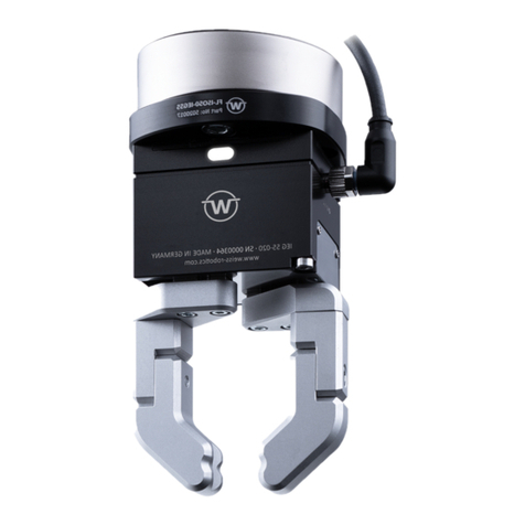
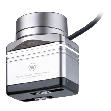
WEISS ROBOTICS CRG Series Technical document

Mounting and Operating Manual
CRG Series - Electrical Gripping Modules with IO-Link
October 2020

- 1 -
Contents
1Introduction ......................................................................................................4
1.1 Product Specification....................................................................................................4
1.2 Applicable Documents ..................................................................................................4
1.3 Target Audience ...........................................................................................................5
1.4 Notation and Symbols ..................................................................................................5
2Basic Safety Notes.............................................................................................. 5
2.1 Intended Use................................................................................................................5
2.2 Environmental and Operating Conditions......................................................................6
2.3 Product Safety..............................................................................................................6
2.3.1 Protective Equipment............................................................................................................ 6
2.3.2 Constructional Changes, Attachments, or Modifications...................................................... 6
2.3.3 Special Standards................................................................................................................... 6
2.4 Personnel Qualification ................................................................................................7
2.5 Safety Considerations ...................................................................................................7
2.6 Notes on Particular Risks ..............................................................................................7
3Warranty ........................................................................................................... 7
4Scope of Delivery and Accessories...................................................................... 8
5Technical Data ................................................................................................... 9
5.1 Nominal Mechanical Data.............................................................................................9
5.1.1 Max. Permitted Finger Length............................................................................................... 9
5.1.2 Gripping Force and Finger Speed ........................................................................................ 10
5.1.3 Cycle Times.......................................................................................................................... 11
5.1.4 Max. Permitted Finger Load ................................................................................................ 12
5.2 Nominal Electrical Data...............................................................................................13
5.2.1 Electrical Interface............................................................................................................... 13
5.3Name Plate ................................................................................................................14
6Installation and Commissioning ....................................................................... 15
6.1 Installation.................................................................................................................15
7Functional Principle of the Gripping Module..................................................... 17
7.1 Typical Application .....................................................................................................18
7.2 Gripping force retention .............................................................................................18

- 2 -
7.3 State visualization by luminous ring ............................................................................19
7.4 Non-volatile Memory .................................................................................................19
8Interface Description IO-Link............................................................................ 21
8.1 Cyclic Process Data .....................................................................................................21
8.1.1 Output Data (IO-Link Master to Gripping Module) ............................................................. 21
8.1.2 Input Data (Gripping Module to IO-Link Master) ................................................................ 22
8.2 Acyclic Process Parameters and System Commands.....................................................24
8.2.1 Remanent Storage of Acyclic Process Parameters.............................................................. 25
8.2.2 Standardized Acyclic Process Parameters........................................................................... 25
8.2.3 Device-specific Acyclic Process Parameters ........................................................................ 26
8.2.3.1 Motion Parameters.......................................................................................... 26
8.2.3.2 Grip Parameters............................................................................................... 28
8.2.3.3 Virtual Position Switches.................................................................................. 30
8.2.3.4 Visualization with luminous ring ...................................................................... 31
8.2.3.5 Diagnosis Parameters ...................................................................................... 34
8.2.3.6 Protocol Memory............................................................................................. 36
8.2.3.7 Extended Configuration Parameters................................................................. 37
8.2.4 System Commands .............................................................................................................. 37
8.3 System Events (IO-Link Events) ...................................................................................38
9Control of the Gripping Module ....................................................................... 40
9.1 Gripping Commands ...................................................................................................40
9.2 Position Sensors .........................................................................................................41
9.3 Reference Run............................................................................................................41
9.4 Virtual Position Switches ............................................................................................41
9.5 Gripping State ............................................................................................................42
9.6 Parameterizable Grips ................................................................................................43
9.6.1 Gripping Direction ............................................................................................................... 44
9.7 Grip Part ....................................................................................................................45
9.8 Release Part ...............................................................................................................45
9.9 Troubleshooting .........................................................................................................46
9.10 Activating and Deactivating the Module (Setup Mode)................................................47
9.11 Gripping force retention .............................................................................................48
9.12 Visualization with illuminated ring ..............................................................................48
9.13 Design of the Gripping Process....................................................................................49
9.13.1 Application Example External Gripping ............................................................................... 50
- 3 -
9.13.2 Application Example Internal Gripping................................................................................ 51
9.14 Function Block for Siemens TIA Portal .........................................................................52
10 Maintenance and Cleaning............................................................................... 53
10.1 Needs-based Maintenance .........................................................................................54
10.2 Resetting the Maintenance Interval Count ..................................................................54
11 Troubleshooting .............................................................................................. 55
11.1 The Base Jaws Do Not Move .......................................................................................55
11.2 Gripping Module Stops Abruptly or Does Not Complete the Entire Stroke....................55
11.3 No Communication with the Gripping Module.............................................................55
11.4 The Gripping Module Reports an Error ........................................................................56
12 APPENDIX A - Device-specific Process Parameters ............................................ 57
13 APPENDIX B - Configuration Example ............................................................... 61
13.1 Preparation ................................................................................................................61
13.2 Configuration of the IO-Link Master ............................................................................61
13.3 Configuration of the Gripping Module.........................................................................64
13.4 Parameterization of the Gripping Module ...................................................................65
13.5 Diagnosis....................................................................................................................66
14 EC Declaration of Incorporation ....................................................................... 67

- 4 -
1Introduction
This manual is an integral part of the gripping module and describes the safe and proper handling during all
operational phases. It is valid solely for gripping modules of the CRG series and contains important infor-
mation on assembly, commissioning, maintenance, and service.
1.1 Product Specification
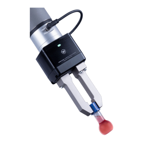
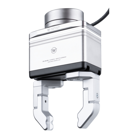
The gripping modules of the CRG series are ultracompact servo-electrical gripping modules with innovative
gripping force regulation and integrated IO-Link technology. Figure 1 shows the connectors and components
of an CRG gripping module. The gripping module can be configured via the configuration software of the IO-
Link master or via the DC-IOLINK device configurator, which is available separately.
Figure 1: Components and connectors of the gripping module
1.2 Applicable Documents
For more detailed information on operating this module, please consult the following documents, which are
available for download on our website at https://www.weiss-robotics.com/crg:
•Technical drawing
•3D model (STEP)
•IO-Link device description file (IODD)
•Function block for Siemens TIA portal

- 5 -
Please find additional information about the warranty in our general terms and conditions, available online
at https://www.weiss-robotics.com/en/general-terms-and-conditions.
1.3 Target Audience
These instructions are targeted at plant manufacturers and operators, who should make this and other doc-
uments permanently available for the personnel and should also ask the personnel to read and observe par-
ticularly the safety instructions and warnings.
In addition, this manual is targeted at professionals and technicians, who should read this manual and should
particularly observe the safety and warning notes at all times.
1.4 Notation and Symbols
For better clarity, the following symbols are used in this manual:
Functional or safety-related information. Failure to comply may jeopardize the safety of per-
sonnel and equipment, damage the device, or impair the functionality of the device.
Additional information for a better understanding of the facts described.
Reference to further information.
2Basic Safety Notes
2.1 Intended Use
The module was designed to grip and temporarily and securely hold work pieces and objects. The module is
intended for installation in a machine/system. The requirements of the applicable guidelines as well as the
mounting and operating notes in this manual must be observed and complied with. The gripping module may
only be used in the context of its defined application parameters and only in industrial applications.
Any other use or use exceeding the intended use is deemed improper, e.g. when the gripping module is used
as a pressing, cutting, lifting, or punching tool, or when it is used as a clamping device or guide for other tools.
The manufacturer is not liable for any damage resulting from such use.

- 6 -
2.2 Environmental and Operating Conditions
The module may only be used within its defined application parameters. It must be ensured that the module
and the fingers are sufficiently dimensioned for the intended application, and that the environment is clean
and the ambient temperature meets the requirements specified in the data sheet. Please observe the
maintenance instructions (see chapter 10). Furthermore, it must be ensured that the environment is free
from splash water and vapors as well as from abrasion or process dust. Excepted are modules that are spe-
cifically designed for dirty environments.
2.3 Product Safety
The gripping module uses state-of-the-art technology and complies with the recognized safety rules and reg-
ulations at the time of delivery. However, dangers may arise from the module if e.g.:
•the gripping module is not used in accordance with its intended purpose.
•the gripping module is installed, modified, or maintained improperly.
•operators do not comply with the EC Machinery Directive, the VDE guidelines, the local safety and
accident prevention regulations, or with the safety and installation notes.
2.3.1 Protective Equipment
To provide protective equipment according to the EC Machinery Directive, a risk assessment in ac-
cordance with applicable standard is necessary.
2.3.2 Constructional Changes, Attachments, or Modifications
Additional bore holes, threads, or attachments not offered by Weiss Robotics as accessories may be mounted
only after obtaining the written approval of Weiss Robotics.
2.3.3 Special Standards
The following standards are met:
•RFI voltage, interference field strength and emission according to EN 61000-6-3
•Fast transients on signal and data lines according to EN 61000-4-4
•HF power input on signal and data lines according to EN 61000-4-6
•HF radiation according to EN 61000-4-3
•Emissions according to EN 61000-6-4 Class A
•Power frequency magnetic field according to EN 61000-4-8
•Static electrical discharge according to EN 61000-4-2

- 7 -
•IO-Link communication standard according to IEC 61131-9
•Robots and robotic devices – Collaborative robot according to ISO/TS 15066:2016
2.4 Personnel Qualification
The assembly, initial commissioning, maintenance, and repair of the module may be performed only by
trained specialist personnel.
Every person commissioned by the operator to work on the module must have read and understood the
complete mounting and operating manual, especially chapter 2 “Basic safety notes”. This also applies to
personnel that is only employed occasionally, e.g. maintenance personnel.
2.5 Safety Considerations
Even though the CRG series are for the collaborative operation, the safety and accident prevention reg-
ulations valid at the operation site must be observed.
Do not move parts by hand when the module is connected to the power supply.
Do not reach into the open mechanical parts and avoid reaching the movement area of the gripping
module.
Disconnect the power supply of the module before any installation, modification, maintenance, or
adjustment work.
2.6 Notes on Particular Risks
Risk of injury from objects falling and being ejected. Take appropriate safety measures to prevent
the falling or ejection of objects, e.g. processed parts, tools, shavings, fragments, waste.
Risk of injury due to unexpected movements of the machine.
3Warranty
The warranty is valid for 24 months from the delivery date to the production facility if the module is operated
in one-shift operation mode and according to the specified maintenance and lubricating intervals, or up to
10 million gripping cycles, respectively. Parts touching the work piece and wear parts are not part of the
warranty. Please also note the general terms and conditions.
The gripping module is considered defective if its basic function “gripping” cannot be performed anymore.

- 8 -
4Scope of Delivery and Accessories
The scope of delivery comprises:
•Gripping module CRG in the version ordered
•Accessory kit (centering sleeves or dowel pins matching the module's diameter)
•Quick guide CRG series
Item
CRG 30-050
CRG 200-085
Gripping module
5010016
5010017
Accessory kit
5020051
5020054
Quick guide
5080033
5080033
Table 1: Part numbers scope of delivery
For the gripping module, the following accessories are available separately:
•Flange adapter for robots with ISO standard flange
•Device configurator for gripping modules of the Integration Line, DC-IOLINK, part number 5020009
•Power supply cables
Please order accessories separately.
More accessories can be found on our website at https://www.weiss-robotics.com.
4.1 Complete solution for Universal Robots
For Universal Robots arms, there is a kit comprising gripping module, flange adapter, control interface, ca-
bles, and mounting material available.
Item
CRG 30-050
CRG 200-085
GRIPKIT designation
GRIPKIT-CR1
GRIPKIT-CR2
Teilenummer
5100006
5100007
Table 2: Part numbers scope of GRIPKIT
More information can be found on our GRIPKIT website at https://www.weiss-robotics.com/grip-
kit

- 9 -
5Technical Data
5.1 Nominal Mechanical Data
Exceeding the specified nominal data may damage the module. If in doubt, please discuss your ap-
plication with our technical sales department.
Mechanical operating data
Unit
CRG 30-050
CRG 200-085
Total stroke
mm
50
85
Nominal gripping force (100%)
N
30
200
Recommended minimum gripping force (50%)
N
15
100
Max. relative finger speed
mm/s
180
140
Min. relative finger speed
mm/s
10
10
Recommended workpiece weight
g
150
1000
Max. permitted finger length (L)1
mm
70
100
Max. permitted mass per finger
g
130
300
Protection class
IP
40
Ambient temperature
°C
5 ... 50
Air humidity
%
0 ... 90 non-condensing
Mechanical repeatability
mm
± 0,03
Resolution of the measuring system
mm
0,01
Working principle of the measuring system
absolute + relative
Weight
g
460
1300
Table 3: Nominal mechanical data
5.1.1 Max. Permitted Finger Length
The maximum finger length Lcorresponds to the distance between the mounting surface of the base jaw and
the point where the gripping force is effectively applied, see Figure 2. The maximum values for Lcan be found
in the nominal mechanical data of the respective gripping module. When the maximum finger length is ex-
ceeded, it is mandatory to reduce the gripping force. Furthermore, the operating life may be reduced.
1At nominal force, see measure “L” in Figure 2

- 10 -
Figure 2: Determination of the finger length “L”. Left: straight fingers, right: angled fingers
5.1.2 Gripping Force and Finger Speed
The gripping force can be set as a percentage of the nominal gripping force. The recommended minimum
gripping force is 50% of the nominal gripping force.
The gripping module sets the finger speed depending on the parameterized gripping force, see Figure 3. This
minimizes the gripping impulse and rebound effects during undamped gripping. The gripping speed can be
increased or decreased manually (and thus adjusted to the part that is being gripped) via the central override
parameter (gray area; see also chapter 8.2.3.1). To ensure proper movement of the fingers, the minimum
possible gripping speed is limited to 10 mm/s.
Figure 3: Gripping speed depending on the parameterized gripping force
L
L

- 11 -
Gripping speeds exceeding 100% (override) lead to an increased gripping impulse that can damage
the part that is being gripped and the gripping mechanism.
5.1.3 Cycle Times
The following diagrams show the typical progression of gripping time and release time for different gripping
force settings.
The displayed values show the typical time from the processing of the command at the gripping
module to the change of the gripping state. The actual time varies depending on the part that is be-
ing gripped (firm or elastic), finger weight, gripping height, etc. For an exact assessment of the possi-
ble cycle times, tests must be carried out in individual cases.
CRG 30-050
CRG 200-085
0
100
200
300
400
500
600
700
800
900
1000
0 2 4 6 8 10 12
Grip Time (ms)
Stroke (mm)
0
20
40
60
80
100
120
140
160
0 2 4 6 8 10 12
Release Time (ms)
Stroke (mm)
0
100
200
300
400
500
600
700
800
900
1000
0 2 4 6 8 10 12 14 16 18 20 22
Grip Time (ms)
Stroke (mm)
0
50
100
150
200
250
300
0 2 4 6 8 10 12 14 16 18 20 22
Release Time (ms)
Stroke (mm)

- 12 -
5.1.4 Max. Permitted Finger Load
The following table shows the maximum permitted static loads on the base jaw guide.
Load
Unit
CRG 30-050
CRG 200-085
C0
N
841
1890
TX
Nm
2.2
6.9
TY
Nm
8.0
26.0
TZ
Nm
7.2
23.6
Table 4: Static guide loads
In the case of overlaid forces and torques, the carrying capacity of the guide must be recalculated according
to the following equation:
+
+
+
0
≤1.0
C0and Tare the permitted guide loads according to Table 4 and Mis the sum of all occurring torques per
base jaw (gripping, weight, inertia, and process forces) in the application.
Figure 4: Finger loads
M
X
M
Y
M
Z
F
Z

- 13 -
5.2 Nominal Electrical Data
Exceeding the specified nominal data may damage the module. If in doubt, please discuss your ap-
plication with our technical sales department.
Electrical operating data
Unit
CRG 30-050
CRG 200-085
Supply voltage
V
18 ... 30
Typ. current drawn (state IDLE)
mA
130
TBD
Max. current drawn (gripping)
mA
300
700
C/Q-Pin
Input voltage range
V
0 ... 30
Threshold “HIGH”
V
13
Threshold "LOW"
V
8
Hysteresis
V
2,2
Communication
Unit
Value
Standard
IO-Link V1.1
Transmission rate
bit/s
38.400 (COM2)
Min. cycle time
ms
4,0
Max. starting time IO-Link2
ms
280
Max. starting time operational readiness3
ms
750
Table 5: Electrical nominal data
5.2.1 Electrical Interface
The gripping module has a four electrical contact. The assignment is shown in Figure 5.
Depending on the build size, the gripping module may draw more current than the 200 mA specified
by the IO-Link 1.1 standard. It is therefore imperative to check whether the IO-Link master can per-
manently provide the nominal current specified in Table 5.
2Time from supply voltage >= 18V until communication readiness via IO-Link
3Time from supply voltage >= 18V until operation readiness of the gripping module (without referencing)

- 14 -
Pin Signal Function
1 L+ Power supply +24 V
2 Q Reserved, do not connect!
3 L- Power Supply 0 V
4 C/Q IO-Link communication
Figure 5: Pin assignment (view on connector)
5.3 Name Plate
The name plate is on the transverse side of the gripping module and contains the serial number, the
hardware version, and the exact type designation.
Figure 6: Name Plate
L+ (1)
L- (3)
Q (2)
C/Q (4)

- 15 -
6Installation and Commissioning
Risk of injury due to unexpected movements of the machine. Disconnect the module from the
power supply during all maintenance work/adjustments and make sure the module is force-free.
6.1 Installation
You can find the dimensions of the threads and centering holes that can be used to mount the module in the
technical drawing of the respective build size. The following maximum torques and minimum screw depths
must be observed during assembly:
Thread
M3
M4
M6
Casing (aluminum)
0.7 Nm
1.3 Nm
3 Nm
Base jaw (steel)
1.3 Nm
3 Nm
10 Nm
Minimum screw depth
3 mm
4 mm
6 mm
Table 6: Tightening torques for screws (min. strength class 8.8)
The gripping module can be mounted from two sides, see Figure 6. A mounting adapter is available for
mounting on a standard ISO flange.
Maximum allowable unevenness of the mounting surface: 0.02 mm
Figure 6: Mounting methods for the gripping module
1
2

- 16 -
Figure 7 shows the mounting of the fingers. The centering sleeves and pins (for build size 30) must be used
for mounting. They can be found in the accessory kit of the gripping module.
Figure 7: Mounting the fingers
The recommended screws and centering sleeves are listed in Table 7.
Position
CRG 030-050
CRG 200-085
1
2 pieces
Centering sleeve 6h6 x 5,5
Weiss Robotics part no. 2090046
2 pieces
Centering sleeve 6h6 x 5,5
Weiss Robotics part no. 2090046
2
2 pieces
Screw ISO 4762 - M4
2 pieces
Screw ISO 4762 - M4
3
2 pieces
Screw ISO 4762 – M3
4 pieces
Screw ISO 4762 – M3
4 2 pieces
Centering pin ISO 8734 - 1.5 m6
2 pieces
Centering sleeve 6h6 x 5.5
Weiss Robotics part no.: 2090046
Table 7: Screws and centering sleeves
3
4

- 17 -
7Functional Principle of the Gripping Module
The gripping modules of the CRG series are servo-electrical two-finger parallel grippers with integrated grip-
ping control, a high-performance brushless drive, and a high-resolution position measuring system, which
has been developed for use in collaborative robot application. Tooth belt kinematics move and synchronize
the base jaws, which are guided by rolling bearings. Due to the pre-positioning capability of the gripping
fingers and the innovative gripping force control, the gripping modules of the CRG series can be used for a
multitude of applications in modern automation. The module is supplied with power and connected to the
process control directly via the integrated IO-Link interface. Rounded edges prevent any injuries when con-
tacting with people thus ensures risk reduction for the design of collaborative applications. Integrated grip-
ping force retention, which prevent slipping out of workpiece, even if the power supply to the gripper is
interrupted unexpectedly, is a safe operation during any operation condition. Figure 8 shows the functional
diagram of the CRG gripping modules.
DriveGear Box
Grip Control
Part
Detection Diagnosis
Virtual Position
Switches
Force
Control
Position
Detection
Figure 8: Functional diagram of the CRG gripping module
The integrated gripping control has a highly optimized gripped-part detection. Up to eight different parts can
be pre-parameterized via IO-Link and gripped reliably. For each gripped part, a position window is set in
which the grip must adjust itself. When the CRG grips in this area, its state changes from RELEASED to HOLD-
ING, which signals a successful grip to the process control. As an alternative to the gripped-part detection,
the position of the base jaws can also be monitored via freely parameterizable virtual position switches.
To detect malfunctions, the CRG monitors all functionally relevant components, such as position sensors and
drive, continuously and provides detailed diagnostic information via IO-Link during operation. Providing us-
age data via IO-Link makes needs-based maintenance possible. For this purpose, the CRG autonomously in-

- 18 -
dicates regular maintenance intervals and lubrication cycles through system events (IO-Link events). The cy-
cles remaining until the next maintenance interval can be queried from the gripping module for better plan-
ning efficiency.
The gripping module has a rigid case made of high-strength aluminum. The base jaws are guided by double
roller bearings and have a ground finger flange. Due to the nickel coated surface, the housing is electrically
discharged and therefore suitable for use in ESD sensitive applications.
Operating states such as errors, warnings or interaction requirements can be visualized via the 360° luminous
ring. So the operator can see at a glance the condition of the system and react accordingly. This allows a user
friendly collaborative application.
7.1 Typical Application
Figure 9 shows a typical control-side setup with CRG series gripping modules that are accessed via PLC and a
decentralized IO-Link field bus coupler. If you need assistance in selecting the IO-Link components, please
contact our technical support.
Damage to the IO-Link master possible. Make sure that the IO-Link master can permanently provide
the required operating current of the gripping module.
Figure 9: Typical application
7.2 Gripping force retention
The gripping module has an integrated gripping force retention which preserve approx. 80% of the gripping
force even if the power supply to the gripper is interrupted. This effectively prevents slipping out of the

- 19 -
gripping part and thus minimize the risk of falling down or ejecting workpiece. The Gripping force retention
works regardless of the gripping direction and required no configuration.
Damage to the gripping module possible: Do not move the gripping jaw by hand in the currentless
state.
7.3 State visualization by luminous ring
A 360° luminous ring is integrated in the gripping module, which can be used to signal the user the different
operating conditions. This cannot be only for the warnings and disturbances but also, especially in collabora-
tive application, can be an advice on user interaction. For this purpose, the luminous ring can be extensively
parameterized. That is also possible to adjust freely the lighting color, the animation (flashing, roatating or
permanent light, etc.) and the animation speed. As the factory setting, different visualizations are parame-
terized, which can be used directly.
Figure 11: Position of the luminous ring
7.4 Non-volatile Memory
The gripping module has a non-volatile memory in which the following information is stored:
•Device-specific factory settings
•Parameterization of the gripping module
This manual suits for next models
4
Table of contents
Other WEISS ROBOTICS Robotics manuals

WEISS ROBOTICS
WEISS ROBOTICS GRIPLINK-ET4 User manual

WEISS ROBOTICS
WEISS ROBOTICS GRIPKIT CR EASY User manual

WEISS ROBOTICS
WEISS ROBOTICS GRIPKIT CR PLUS Series User manual

WEISS ROBOTICS
WEISS ROBOTICS IEG Series Technical document

WEISS ROBOTICS
WEISS ROBOTICS GRIPLINK User manual

WEISS ROBOTICS
WEISS ROBOTICS GRIPLINK-ET4 User manual

WEISS ROBOTICS
WEISS ROBOTICS GRIPKIT CR EASY User manual

WEISS ROBOTICS
WEISS ROBOTICS GRIPKIT CR PLUS User manual

WEISS ROBOTICS
WEISS ROBOTICS GRIPKIT CR EASY User manual

WEISS ROBOTICS
WEISS ROBOTICS GRIPKIT CR PLUS User manual