ArcWorld IV-6200 XHD DR2C System Manual iv
MOTO
MAN
LIST OF FIGURES
Figure Page
Figure 1-1 System Layout........................................................................................................... 1-2
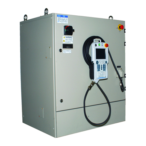
Figure 3-1 DR2C XRC 2001 Controller – R1 and R2.................................................................. 3-1
Figure 3-2 External Axis Cabinet Components ........................................................................... 3-2
Figure 3-3 XRC 2001 Playback Panel.........................................................................................3-3
Figure 3-4 Programming Pendant .............................................................................................. 3-4
Figure 3-5 RS-232C Serial Port.................................................................................................. 3-6
Figure 3-6 Enable Switch............................................................................................................ 3-6
Figure 3-7 Operator Station Control Panel.................................................................................. 3-7
Figure 3-8 Available Power Sources.........................................................................................3-12
Figure 3-9 Service Disconnect Locations ................................................................................. 3-13
Figure 4-1 System Components................................................................................................. 4-2
Figure 4-2 Area Needed for Installation ...................................................................................... 4-3
Figure 4-3 Shipping/Leveling Bolts............................................................................................4-4
Figure 4-4 Floor Anchors ........................................................................................................... 4-5
Figure 4-5 Positioner Shipping Brackets.................................................................................... 4-6
Figure 4-6 Positioner Anchor Locations..................................................................................... 4-6
Figure 4-7 Robot Common Base Installation.............................................................................. 4-7
Figure 4-8 Robot Common Base Leveling Points....................................................................... 4-8
Figure 4-9 Location of Shipping Brackets................................................................................... 4-9
Figure 4-10 Install Programming Platforms................................................................................ 4-10
Figure 4-11 Unbolting Auxiliary Equipment Common (AEC) Base ............................................. 4-11
Figure 4-12 AEC Base Installation Location................................................................................ 4-12
Figure 4-13 Cable Routing ......................................................................................................... 4-13
Figure 4-14 Ground Welding Cable on Positioner......................................................................4-15
Figure 4-15 Positive and Negative Terminals on the Welding Power Source.............................. 4-15
Figure 4-16 Connecting the Controller to the Robot................................................................... 4-17
Figure 4-17 Positioner Interface Panel Installation ..................................................................... 4-18
Figure 4-18 Crated Fencing Skid................................................................................................ 4-19
Figure 4-19 Fence Wall Identification......................................................................................... 4-20
Figure 4-20 Left Side Fence Wall Assembly – Steps A and B..................................................... 4-21
Figure 4-21 Fence/Post Connections – Left Side ....................................................................... 4-21
Figure 4-22 Fence Anchor Points – Left Side............................................................................. 4-22
Figure 4-23 Left Fence Wall Assembly – Steps C through E ...................................................... 4-22
Figure 4-24 Connect Quick-Access Wall – Left Side.................................................................. 4-23
Figure 4-25 Left Fence Wall Assembly – Step F......................................................................... 4-24
Figure 4-26 Right Side Fence Wall Assembly – Steps A and B .................................................. 4-25
Figure 4-27 Fence/Post Connections – Right Side..................................................................... 4-26
Figure 4-28 Fence Anchor Points – Right Side........................................................................... 4-26
Figure 4-29 Right Fence Wall Assembly – Steps C through E.................................................... 4-27
Figure 4-30 Connect Quick-Access Wall – Right Side ............................................................... 4-28
Figure 4-31 Right Fence Wall Assembly – Step F....................................................................... 4-28
