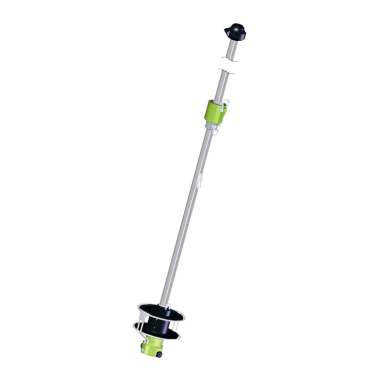
ProFurl MK0 User manual


MK 0
2
Congratulations for the purchase of your PROFURL
in-boom reefing furling system.
Please read carefully this manual. It will give you to all information for fitting and using your
system in order to give you many years of dependable service.
IMPORTANT WARNING FOR USING
YOUR SYSTEM :
!The PROFURL boom is obviously heavier than a conventional boom.
Avoid uncontrolled gibing, specially with strong wind, as you could
permanently damage your system.
Reminder to gibe :
1 - take in or winch your main traveller and main sheet
2 - turn your boat to gibe
3 - gradually release your main traveller and main sheet.
You can even better fit a tackle as boom preventer (see drawing).
You can also fit a boom brake, but you must not forget to completely
release it each time you want to operate your system.

MK 0
3
CONTENTS
Page 2 Important warning to use your system
Page 3 Preliminary cautions
Page 4 General description
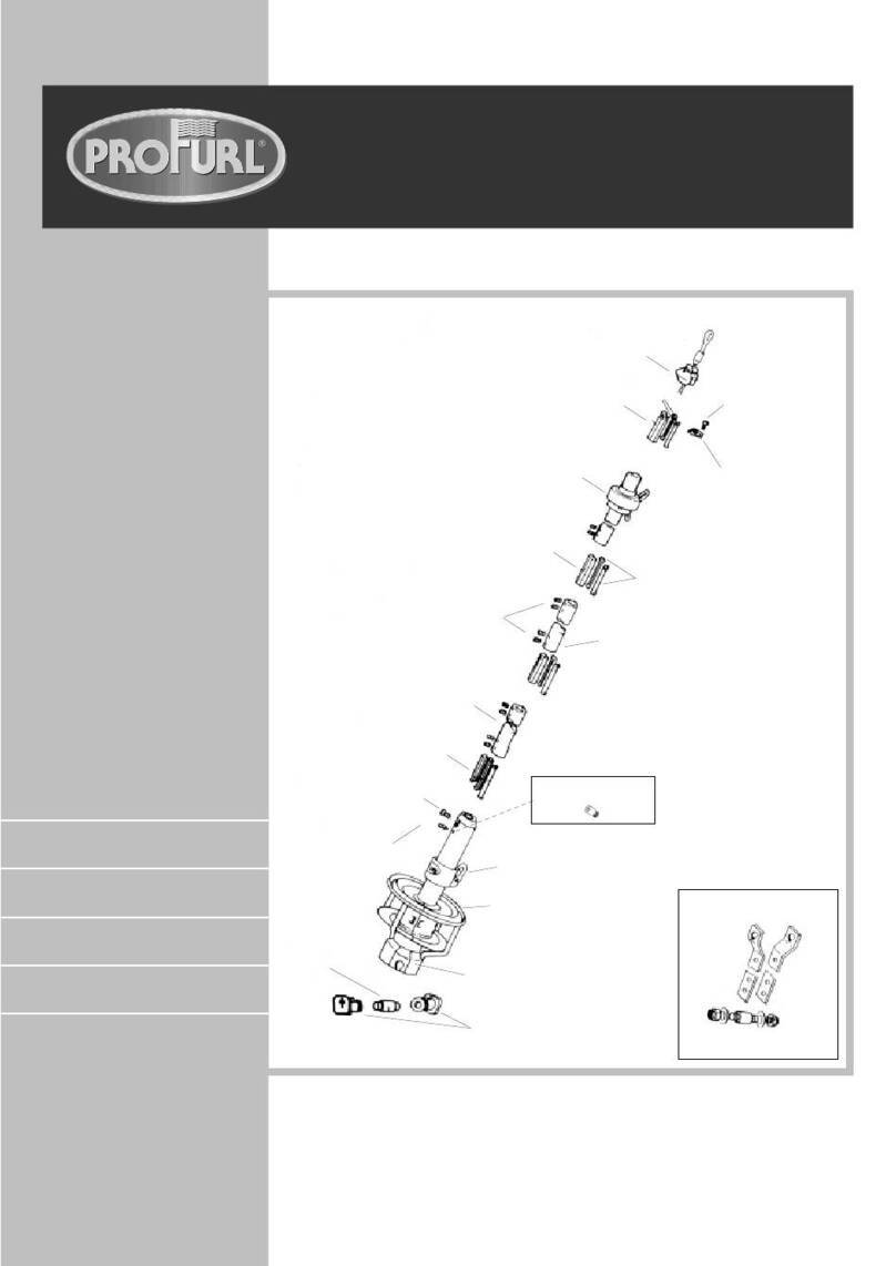
Page 5 Exploded view
Page 6 Tools needed for fitting
Page 6/7 Unfitting the hardware from the mast
Determining the height of the gooseneck
Page 7 Fitting the slide screws in the mast track.
Page 8 Fitting the gooseneck.
Page 8/9 Assembling the luff profiles.
Page 10/11 Fitting the articulation brackets onto the mast / the
sheave box.
Page 12 Measuring and fitting the upper luff profile.
Fitting the upper luff profile onto the sheave box.
Page 13/14 Cutting the boom to length
Page 15 Cutting the mandrel to length. Fitting the mandrel onto
the boom.
Page 16 Fitting the boom onto the gooseneck.
Page 17 Fitting the boomvang hound onto the mast.
Page 18 Adjusting the position of mainsheet bails.
Installing the control lines to the cockpit
Page 19 Fitting the mainsail
Page 20/21 Feeder adjustment.
Page 21 Adjustment of the boom angle to the mast.
Page 22 Using the system.
Limits for using the system
Page 23 Warranty conditions - Warranty form
PRELIMINARY CAUTIONS
The PROFURL in-boom mainsail reefing system is not designed to be installed on
wooden masts, or aluminium masts with track added with screws, rivets, glue or any
similar assembly. Fitting on a carbon mast is not recommended an requires special
skills. Please contact us.
Please check that there is no sign of severe corrosion on the mast which would
compromise the strength of the assembly.
The person in charge with fitting will be fully responsible for installation and adaptation
on board according to the specifications shown in this manual.

MK 0
4
I- GENERAL DESCRIPTION
Note : names in bold refer to parts shown on the exploded view (next page)
The PROFURL MK0 in-boom furling system includes :
1. One set of luff profiles (1 and 2) articulated on the aft face of the mast.
There are 2 different kinds of luff profiles: one 0.40 m long feeder profile (1) on which the
feeder (21) is attached, and several 2 meters long normal luff profiles (2) depending on the
mainsail’s luff length. One of these 2 meters long normal luff profiles (2) will be re-cut to
length at its upper end to match the expected luff length of the mainsail. The different luff
profiles (1 et 2) are connected to each other by mean of connectors/articulations (4),
which are fitted to articulation brackets (5) that will be attached to the mast track.
2. Articulation brackets (5) attached to the mast with 2 slide screws (7) slipped in the mast
groove. Every slide screw (7) has a thread and a flat end going through a hole of the
articulation brackets (5). The thread of the slide screws (7) receives a washer (33) and a
locknut (8) for attachment.
3. Connectors/articulations (4) are also used to connect the different luff profiles (1 and 2),
held by set screws (9). The lower end of the 0.40 m long feeder profile (1) will be
connected onto the gooseneck articulation (10), thus allowing the luff profiles (1 and 2) to
rotate together with the boom.
4. A sheave box (11) through which the original mainsail halyard is passing. The sheave box
(11) will be fit at the top of the luff profiles (1 and 2). It is assembled on the end brackets [2
times 5a], themselves being attached by mean of slide screws (7) washers (33) and
locknuts (8) and pin (66).
5. A gooseneck (12) fit on the mast with 2 slide screws (7), and two gooseneck plates (13)
cambered at the mast shape while fitting, and which will be riveted onto the mast with the pop
rivets (14) supplied.
6. A boom profile (15) which has been delivered in 3.20 meter (10’ 6”). It may be necessary to
re-cut the boom profile to length when fitting to match the expected boom length.
7. A mandrel (16) turning on bearings (17) fit on a bearing holder (19) at the rear end of the
boom, and on the drum-bearing holder (24) front, turning around a pin inserted in each of
the boom end fittings (22 and 23). When re-cutting the boom profile (15) to length, the
mandrel (16) should also be re-cut by the same amount.
8. A drum boom end fitting (22). It includes the drum-bearing holder (24) fit on the mandrel
(16): the drum being loaded with the furling line, pulling on the furling line while releasing the
mainsail halyard will rotate the mandrel (16), which will furl the sail.
9. 2 adjustable mainsheet bails (25).
10. A special boomvang (26). It is attached :
- to the mast by mean of a boomvang attachment, including an gooseneck (12)
attached onto the mast with 2 slide screws (7) washers (33) and locknuts (8) and two
gooseneck plates (13) which will be riveted to the mast with the pop rivets (14)
supplied. The boomvang lower end will be attached onto an articulation fitting (48)
rotating in the boomvang gooseneck.
- onto the boom with an adjustable boomvang hound (28).

MK 0
5

MK 0
6
TOOLS NEEDED FOR FITTING
In all cases of fitting
nA tape line
nAn electric drill
nA set of drills
nA hack saw with a (new) blade with small teeth
nA file
nA pencil
nA plastic hammer
nA metric10 mm pipe-wrench
nA metric 17 mm pipe-wrench
nA dynamometrical wrench (1daN/m)
n1 set of Allen wrenches (supplied)
n2 clamps with a minimum opening 200 mm (7”)
nUniversal pliers
nA cutter blade (with new blades)
nA large sheet of paper with corners perfectly at 90° and adhesive tape
nSeveral small plywood or rubber shims.
nA pop rivet gun for 5 mm rivets.
Note : the plates to fit the gooseneck and boomvang attachments are 4 mm thick and
made out of aluminium. A convenient set of clamps with minimum 150 mm (6”) opening
should be used to bend them at the mast shape.
If the fitting is made on a standing mast
nA Boson’s chair
nSome short ropes of 6 or 8 mm (1/4” or 5/16”) diameter
Please purchase a 6 mm furling line and a ball bearing block to lead the furling line to the
cockpit.
II - PREPARATION
II.1 - UNFITTING THE HARDWARE FROM THE MAST
II 1 a - Dismantle the original gooseneck, as well as cleats, winches and winches brackets
on the mast, as well as any piece of equipment which would interfere with the fitting of the
new gooseneck and with the ability for the forward boom end fitting to rotate when the
boom will swing from one side to the other. Please see § III 1 b and drawing 1 for
dimensions of the new gooseneck in relation with mark « C » on the mast.
II 1 b - The original boomvang attachment should not be used, as the rotation axis of the
boom and of the new gooseneck need to be in line, which would never be the case with the
original boomvang attachment.
II 1 c - Dismantle the original feeder (if any) at the mast track entrance.
II 1 d -Check that the slide screws (7) supplied have suitable dimensions for the mast
track. If not, their width should be modified (turned, machined, grinned, filed) accordingly.
In all other cases please contact us.

MK 0
7
III - INSTALLATION
III 1 - DETERMINING THE HEIGHT OF THE GOOSENECK
III 1 a -To avoid any potential conflict between the boom and the cabin top, a bimini, a
lifeline or any other piece of equipment, please accurately mark the level of the lower edge
of the original boom. Please see drawing 1.
III 1 b - Check that the boomvang delivered with your system will make once installed a
minimum 30° angle with the mast and the boom. Should it not be the case, the position of
the new gooseneck must be raised on the mast in order to obtain at least this 30°angle .
Note pin to pin boomvang length : 1100 mm (5’ 87/8”) open / 1005 mm (5’ 33/16”) closed
III 1 c - Draw a line « C » on the mast at the level of the lower edge of the original boom.
Please see drawing 1.
III 1 d - Draw a line « B »on the mast at 267mm (10’ 2 33/64”) above line «C ».The line
«B » will correspond to the level of the upper edge of the gooseneck plates (13) once fit on
the mast.
III 2 - FITTING THE SLIDE SCREWS INTO THE MAST TRACK
III 2 a - Insert the head of the slide screws (7) into the mast track. The number of slide
screws you need to insert depends on the number of articulation brackets :
A- 2 slide screws are needed for the boomvang attachment. Slide these slide
screws down to the mast foot to later fit the boomvang attachment .
B- Slide 4 slide screws (7) into the mast track for the upper end brackets
(5).
C - Slide as many times 2 slide screws (7) into the mast track as the quantity of
articulation brackets (5) to be fit. See drawing 12.
III 2 b - Move the stacked slide screws mentioned in Band Cupwards on the mast above
the mast track opening, and temporarily hold them with adhesive tape to prevent them
slipping out of the track.
III 2 c - Slide 2 extra slide screws (7) into the mast track for fitting the gooseneck.
Drawing 1

MK 0
8
III 3 - FITTING THE GOOSENECK
III 3 a - Attach the gooseneck at the convenient height (§ III 1) with the 2 corresponding
slide screws (see § III 2 c), washers (33) and locknuts (8). Tightening torque must be 1
daN/m. Please see drawing 1.
III 3 b - Bend the aluminium gooseneck sideplates (13) with clamps to accurately camber
them to the mast shape. During bending please protect the plates from dings and dents.
III 3 c – Fit the gooseneck onto the sideplates with the rivets. Would the sideplates be too
long, they can be re-cut if necessary, keeping in mind too much length is always better than
too little.
III 3 d - Draw lead lines for drilling on the side plates (13). Press the side plates on the
mast with clamps ( please protect the plates with convenient means). There should have at
least 8 pop rivets (14) on the mast on each side plate (13).
III 3 e -Temporarily fit the gooseneck articulation (10) onto the gooseneck (12) as well as
washers 20 and 30, and tighten the counternut (30a) and locknut (31).
III 4 - ASSEMBLING THE LUFF PROFILES
Note: assembling the luff profiles will be easier flat on the ground.
III 4 a - Fit the luff profiles (1 et 2) together starting with the feeder profile (1) where the
feeder (3) is attached. The lower end of this feeder profile can be identified by the luff
grooves have been machined off. Please see drawing 2.
III 4 b - Completely insert a connector/articulation (4) at the upper end of the feeder profile
(1) . Please see drawing 2.
III 4 c - Fit and tighten the set screws (9) at the upper end of the feeder profile.
III 4 d - Fit a 2 meter long normal luff profile (2) onto the connector/articulation (4) which has
been fit as described above.
III 4 e - Fit and tighten the set screws (9) onto the luff profiles. Fit all the luff profiles (2) with
the same method except the last 2 meter normal profile. Please see drawing 3.
III 4 f -Hoist the above luff profiles column from the aft side of the mast by preferably using
the existing topping lift.
Caution: during hoisting check that the luff profiles are kept as straight as possible.
Drawing 3
Drawing 2

MK 0
9
III 4 g - Completely insert the lower end of the feeder profile (1) into the striped aluminium
connector of the gooseneck articulation (10) . Please see drawing 4.
III 4 h – Check fitting order of washers and nuts (3, 20 ,30, 30a, 31) onto the vertical stainless steel pin.
Please see drawing 4. Permanently fit the Nylock nut (31) with a 17 mm tube wrench onto the thread of the
stainless steel vertical pin. Fit the plastic cap (32) over the locknut.
III 4 i– Go to mast head taking with you:
•the 2 end brackets (5a)
•all the articulation brackets (5)
•the sheave box (11)
•all the slide screws (7) to be slipped up in the mast track, washers (33)
and locknuts (8).
Drawing 4

MK 0
10
III 5 - FITTING THE ARTICULATIONS BRACKETS ONTO THE MAST
III 5 a - Consider the 2 lower slide screws (7) stacked above track entrance.
III 5 b - Fit an articulation bracket (5) on the mast with these slide screws (7). Please see
drawing 5.
III 5 c - Fit the washers (33) and locknuts (8) onto the thread of the slide screws (7).
Tightening torque should be 1 daN/m.
Caution : during fitting the articulation brackets (5) onto the connector/articulations (4),
double check that the feeder profile is permanently and fully inserted in the gooseneck
articulation (10).
III 5 d - Continue fitting all the articulation brackets (4 & 5) with the same procedure.
III 6 - FITTING THE SHEAVE BOX
III 6 a - Slide up in the mast track the 4 uppermost remaining slide screws (7).
III 6 b - Temporarily fit the 2 end brackets (5a) and the sheave box (11) so that the rear
upper end of the sheave box leaves a minimum clearance of 20 mm with the backstay(s).
Please see drawing 6.
Drawing 5
Drawing 6

MK 0
11
III 6 c - Draw an « A »line on the mast corresponding to the position shown on drawing 7.
Drawing 7

MK 0
12
III 7 - MEASURING AND FITTING THE UPPER (CUT) LUFF PROFILE
III 7 a - Accurately measure the length« A to D », D being the upper edge of the articulation
bracket. Please see drawing 8.
III 7 b - Mark the « A to D » length on the remaining luff profile (2) and cut it at this exact
length. File smooth the cut edge .
Note : in case you have a fractional rig or a very flexible mast, please cut upper profile at
A/D minus 5 mm (13/64”), but keep the sheave box at the same position, thus giving 5
mm play between “A” and the upper edge of the cut profile.
III 7 c - Fit without tightening the 2 set screws (9) on the threads located at the opposite
side of the cut end.
III 7 d - Assemble the cut luff profile onto the next to last 2 m profile (2).
III 8 - FITTING THE UPPER (CUT) LUFF PROFILE ONTO THE SHEAVE BOX
III 8 a - Completely insert the striped aluminium bar of the sheave box (11) into the upper
cut end of the luff profile (2).
III 8 b - Insert the bottom end of the luff profile (2) into the next lower connector/articulation
(4).
III 8 c - Fit again the sheave box (11) onto/between both end brackets (6) and fit and fasten
the 4 slides screws (7) to permanently secure this assembly.
III 8 d - Tighten the set screws (9) at the bottom end of the cut luff profile (2).
III 8 e - Follow the path for the mainsail halyard as shown on drawing 8.
Drawing 8

MK 0
13
III 9 - CUTTING THE BOOM PROFILE AND THE MANDREL TO LENGTH
III 9 a-HOW TO CALCULATE THE LENGTH OF THE BOOM PROFILE.
Case # 1: The PROFURL boom overall length should be the same as the one
delivered.
Case # 2: The PROFURL boom being delivered in over length, the opportunity may be
taken to make the boom longer. Caution : changing the boom length could
affect the balance at the helm when sailing under sails. In this case check
that the aft end of the boom cannot touch the backstay or any other piece of
equipment on board.
In both cases please refer to drawing 9 for dimensions.
The PROFURL in-boom reefing system is delivered pre-assembled. The boom profile (15)
and the mandrel (16) may have to be re-cut to length to match the boat’s requirements
when fitting the system.
CAUTION : should the complete length of the boom profile be used, the
rear boom end fitting is just temporarily attached to the boom profile
for shipping. Please follow the rear end boom fitting assembly
procedure from § III 9 c 5 and on as if the boom profile had been re-
cut.
III 9 a 1 - To cut the boom profile (15) and the mandrel (16) to length, first dismantle the
rear boom end fitting (23) from the boom profile and pull out the mandrel (16) from the
boom profile.
Drawing 9

MK 0
14
Caution : during dismantling, the mandrel (16) will not be held any more. Please keep
control about the mandrel potentially falling down when pulled backwards. Also mind not
to lose the washers (20 & 20a) located forward of the drum (24) .
III 9 a 2 - To re-cut the boom profile (15) to length, and to make sure that the cut section is
accurately perpendicular to the profile, wrap a sheet of paper or mylar (with accurate right
angle corners) so that the edges are in perfect line, and attach it with adhesive tape.
Please see drawing 10. Draw a line on the boom profile, following the edge of the sheet
where the boom profile will be cut.
III 9 a 3 - Cut the boom profile according to the line and file smooth.
Drawing 10

MK 0
15
III 9 b-CUTTING THE MANDREL TO LENGTH
The mandrel (16) should be re-cut of exactly the same length of the one having been
cut off from the boom profile.
III 9 b 1 – Remove the bearing holder (19) + bearing (17) assembly from the rear end of
the mandrel (16).
III 9 b 2 - Cut the mandrel (16) at its rear end with the same method as the one having
been used for cutting the boom profile (15). Same as § III 9 a2. File the rear (cut) end of
the mandrel and foot track ends smooth.
Caution : the forward (drum) end of the mandrel (16) must not be cut!
III 9 b 3 - Fit again the bearing (17) and bearing holder (19) into the cut/rear end of the
mandrel. Tap at M6 (6mm) at 30 mm from the cut end. Fit and tighten the screw (29).
III 9 b 4 - In case the mandrel has been cut a little too short, the fore and aft play must be
reduced to a minimum. To do this, loosen screw (29), push the mandrel forward, pull out the
bearing holder (19) so that the washer (20) touches backwards, tighten again screw (29).
III 9 c- FITTING THE MANDREL ONTO THE BOOM
III 9 c 1 - Fit the mandrel (16) into the boom profile (15), fit the washer (20) and the drum bearing (18) onto
the stainless steel pin (36) inserted in the drum boom end fitting (22).
III 9 c 2 - Check that the mainsheet bails (25) and boomvang hound (28) are properly fit in the bottom track
of the boom as shown on drawing 12.
III 9 c 3- Slide the bearing (17) located at the rear end of the mandrel (16) onto the stainless steel pin
inserted in the rear boom end fitting (23).
III 9 c 4 - Completely insert the rear boom end fitting over the rear (cut) end of the boom profile (15). A
ratchet tie down strap is a handy tool to do this.
III 9 c 5 - Drill holes ∅5mm at the rear end of the boom profile (15) through the pre-drilled holes of the rear
boom end fitting (23). Fit the corresponding pop rivets (37) supplied into these holes to permanently attach
the boom end fitting onto the boom profile.
Drawing 11

MK 0
16
III 10 - FITTING THE BOOM ONTO THE GOOSENECK
III 10 a- Hoist the boom with a halyard and a topping lift (see drawing 12) by keeping it as horizontal as
possible.
III 10 b – Fit horizontal pin (34) . Fit and open split pin (35)
Caution : do not drop or raise the boom more than 15° from horizontal position as it could cause
permanent damage to the gooseneck.
From this stage and on the luff profiles and the boom must turn together.
Drawing 12

MK 0
17
III 11 - FITTING THE BOOMVANG HOUND AND THE BOOMVANG
Reminder: the ideal working angle of the boomvang being 45° the boomvang must not angle less than 30 °
with the mast or boom.
III 11 a- Fit the boomvang attachment (12) with the 2 slide screws which had been stored at the mast foot
(please see § III 2 a A).
III 11 b - Bend the aluminium gooseneck sideplates (13) to the mast shape. During
bending please protect the plates from dings and dents.
III 11 c - Would the sideplates be too long, they can be re-cut if necessary, keeping in mind
too much length is always better than too little.
III 11 d - Draw lead lines for drilling on the side plates (13). Drill at Ø 5 mm and fit the pop
rivets (14) on the side plates . There should have at least 8 pop rivets (14) on the mast on
each side plate.
III 11 e – Fit washer 20 onto the articulation eye. Fit the articulation eye (49) with the eye preferably
downwards onto the gooseneck attachment, fit in this order washers 20 (plastic) and (SS) 30, low nut 30a
and Nylock 31 . Please see drawing 13. Note - in some cases you maybe brought to fit the articulation eye
(49) upside down: providing the boomvang angle to the boom is still more than 30°, it is a mechanically
acceptable option.
III 11 f - Fit the boomvang onto the articulation eye (49) and onto the boomvang hound (28). Fit the pins and
the split pins.
Drawing 13

MK 0
18
III 12 - ADJUSTING THE POSITION OF THE MAINSHEET BAILS (25)
III 12 a - Adjust the position of the mainsheet bails (25) with the set screws which can be reached from
underneath. Fasten the mainsheet blocks on the mainsheet bails.
CAUTION : on boats with a mainsail track or mainsail block attachment on deck ahead of the main hatch
the mainsheet bails (25) must be re-positioned as far backward as possible.
III 12 b - Push the boom by hand over the lifelines as far as possible and tie a knot on the mainsheet so
that in no case the boom profile can be damaged by the rearmost shrouds when running downwind or jibing.
III 13 - INSTALLATION OF THE CONTROL LINES TO THE COCKPIT
REMINDER TO AVOID FRICTION
1. Only use good quality ball bearing blocks, which will have to be cleaned and lubricated from time to time
as per manufacturer’s specifications.
2. Use ball bearing blocks with a sheave of large diameter.
3. Reduce as much as possible the number of lead blocks between the drum and the cockpit.
4. Reduce as much as possible the angle of deviation of the control lines.
III 13 a - Attach on starboard a ball bearing block (not supplied) to the mast foot at the convenient position
to lead the line into the middle of the drum at 90° angle .
III 13 b - Pass the furling line from underneath through the block, then through the hole of the drum’s shaft
and a tie small knot at its end so that the knot will be completely hidden inside the drum’s shaft. Please see
drawing 14.
III 13 c - To fill the drum with line turn the mandrel (16) by hand towards port side (seen from above) : the
furling line should exit from the drum on the starboard side.
III 13 d - Fit another ball bearing block at the mast foot to lead the mainsail halyard to the cockpit. Remind
to use the right type and dimensions of blocks.
III 13 e - Check that the exit from the mast of the mainsail halyard does not bring too much chafe.
Drawing 14

MK 0
19
IV - FITTING THE MAINSAIL
⇒Please check again that the foot track rear end has been smooth filed before starting inserting the
foot tape into the mandrel’s foot track.
CAUTION : before operating the PROFURL in-boom reefing system please make sure that :
1) the mainsail construction and design are in accordance with the attached specifications. Please
refer to attached mainsail design specifications.
2) the boomvang angle adjustment ( see § VI ) is correct. This adjustment is an essential point to get
a good quality furling of the mainsail as well as ease of operation.
IV 1 - Turn the mandrel (16) by hand so that the foot track of mandrel is upwards.
IV 2- Do not yet insert the mainsail battens into the batten pockets.
IV 3 - Insert the tack slide (38) with the “hook” to the front into the tack webbing of the sail. Insert
together both webbing and tack slide into the port side foot track. Please see drawing 15.
IV 4 - Insert the bolt rope foot tape into the track and gently pull the sail forward.
IV 5 - Once almost at the end insert the clew slide (39) into the clew webbing so that the webbing is
locked between the two small plastic cylinders of the clew slide (39), and insert the clew slide into the
groove of the mandrel (16). Please see drawing 16.
IV 6 - Lock the “flat” part of the tack slide to port into the machining of the front end of the foot track and
pull the sail backwards to lock.
IV 7 - Slide the « finger » of the clew pin (43) with the ring upwards into the foot track (16). Please see
drawing 16.
Drawing 16
Drawing 15

MK 0
20
IV 9 - Lash a line between the clew webbing and the ring of the clew pin (43) and adjust foot tension.
Check to tie or cut any loose extra length of lashing line.
IV 10 - Insert the battens into the batten pockets.
IV 12 - Attach the halyard onto the head of the mainsail.
IV 13 - Unscrew by about 3 turns only the starboard side plastic knob (32) of the feeder (21) to increase
the gap between the bronze rollers (36).
IV 14 - Slide the « continuous » port side luff tape between the bronze rollers and hoist by hand only a
few centimetres/inches of sail.
V - FEEDER ADJUSTMENT
The feeder has features allowing :
* to very accurately trim the gap between the 2 bronze rollers (36) to exactly match the bolt rope
diameter.
* to quickly increase the gap between the bronze rollers to easily insert the bolt rope/luff tape into the
groove of the luff profiles after the sail has been furled or removed.
* to instant bring back the correct gap for feeding the sail into the groove of the luff profile to use the
system .
V 1 - ADJUSTMENT OF THE GAP BETWEEN THE ROLLERS (Please see drawing 17)
V 1 a - Screw by hand but do not over tighten the starboard side knob (32) of the feeder.
V 1 b - Adjust the starboard side screw (29) with an Allen wrench, till feeling that the luff tape in
pinched. Then unscrew it back by about ¼of turn to make the luff tape free to slide up and down. The
adjustment is now correct.
V 1 c - Hoist the sail by gently pulling on the halyard.
V1d- To lower or furl the sail, gradually release the halyard while pulling on the furling line.
Drawing 17
Table of contents
Other ProFurl Boating Equipment manuals
Popular Boating Equipment manuals by other brands

Teleflex Marine
Teleflex Marine B700SS manual

Airmar
Airmar Sealcast TM258 Owner's guide & installation instructions

Ultraflex
Ultraflex UC130-SVS Installation and maintenance manual

Wilderness Systems
Wilderness Systems Helix MD quick start guide

Navnet
Navnet TZ 2 touch Installation checklist

DAVIS
DAVIS Mark 3 manual

Garelick
Garelick 71095 Mounting and operating instructions

Seakeeper
Seakeeper 5 GYRO Operation manual

Vetus
Vetus PL Series Operation manual and installation instructions

Harken
Harken 3355 instructions

Attwood
Attwood 4620 Series installation instructions

SLO Sail and Canvas
SLO Sail and Canvas Supercat 17 Trampoline Measurement guide