Care and Maintenance
I. Besuretocheckandtightenallfastenersandconnectionspriortoeveryuse.
II. Alwaysrinserackaftercontactwithsalt(brackish)water.
III. Becautiouswhentowingordrivingunderobstacles,lowhangingstructuresortrees.
JOBE Addict Adjustable Ski Pylon Warranty
JobeSportsInternationalwarrantsthisproduct(notincludingother3rdpartyaccessories)againstmanufacturersdefects.Anodizingandpowdercoatedsurfa-
cesaswellasallhardwarecorrosionarespecicallyexcludedastheircareandusecannotbecontrolledbyJobeSportsInternational.Anymodicationsor
improperuseshallvoidthiswarranty.JobeSportsInternationalisnotresponsibleforpersonalinjuryordamagetotheboatcausedbytheuseofthispylon.
JOBE’sobligationunderthiswarrantyshallnotincludeanytransportationchargesorcostsofinstallationoranyliabilityfordirect,indirectorconsequential
damagesresultingfromdelayorimproperinstallation.Nodealer,retailerormanufactureristheagentofJobeSportsInternationalandmaynotassumeforJobe
SportsInternationalanyliabilityinconnectionwiththiswarranty.Thiswarrantyisinlieuofall.
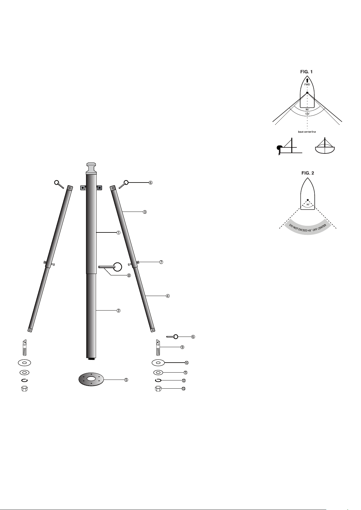
Step 1
Assamblethepylonontheground.Youwillnotbedrillingholesinthepylonatthispoint.
Usethebigclevishitchpintoassamblepart(1)and(2)ofthemainpylon.Nowscrewthemainpylonintothebaseplate(5)andsetittothe
desiredheight.Placetheouterbracearmsintothethruclevisonthepylonandpinwiththe1/4”x1”clevishitchpins.
Step 2
Positionthepylontotherearoftheboatattheboat’scenter-line.Checkthatthetelescopingarmsreachthecorrectinstallationposition.
NOTE- Necessary hardware for the next step not supplied.
Step 3
Installthepylon’sbaseplatetothebottomoftheboatusing1/4-20boltsandlargesurfaceareawashers
ontheunderside.Ifaccesstotheundersideisnotpossibletosecuretheboltswithnuts,use5/16”lag
screwsandsealwithsilicone.Theoormustbeatleast3/4”(2cm)thicktouselagscrews.
Step 4
Nowinserteachinnerportionofthetelescopingbracearmsintoanouterportion.Positionthemtotheback
oftheboatat45˚-50˚otheboat’scenter-linefromthemainpylon(Figure1).Thetotalangleofleftand
rightbracesshouldbesomewherebetween90˚-100˚.
NOTE- Braces that are too close together could cause the pylon to collapse.
Step 5
PRIOR TO DRILLING: Check
to make sure that there
aren’tanyobstructionssuch
ascablesorwires.Markyour
spots on the boat deck to
drillholes forthe deckcle-
vises(9).Makesurebothsi-
desaresymmetrical.Ensure
markedareacanbereached
frombelowfortheinstalla-
tionof theat washer(11),
lock washer (12) and nut
(13).
Step 6
Removethebracesfromthedeckanddrill5/8”holesthrou-
ghthemarksyoumadeinStep5.Usingcleviswashers(10),
insertthedeckclevises(9)throughtheholesyoujustdrilled.
Nowusetheatwasher(11),lockwasher(12)andnut(13)
tosecureeachclevis(tightenrmly).
NOTE-Ifthedeckisnotatleast1/2”thickatthemounting
points,youmust addapiece ofmarineplywoodorsimilar
itemtotheundersideofthedecktodistributetheload/add
strength.
Step 7
Withthesupportbracesattachedtothepylon,connectthe
otherendstotheappropriatedeckclevis.Onepersonapply
slightforwardpressuretothepylonwhiletheotherperson
usestheouterbracepilotholestodrilla1/4”holethrough
eachinnerbrace.Disconnectthebracesfromtheboat.Bolt
eachbracethroughthedrilled holesusing1/4”x1¼”bolt
andnylonnut(7).Reconnectthebracestotheboat.


