Kimo DBM610 User manual

DBM610
AIRFLOW METER


Table of contents
1. Introduction....................................................................................................................................................................... 4
1.1. Key points................................................................................................................................................................. 4
1.2. Technical features..................................................................................................................................................... 4
1.3. General technical features........................................................................................................................................ 5
2. Presentation of airflow meter............................................................................................................................................ 6
2.1. ase.......................................................................................................................................................................... 6
2.2. Grid........................................................................................................................................................................... 7
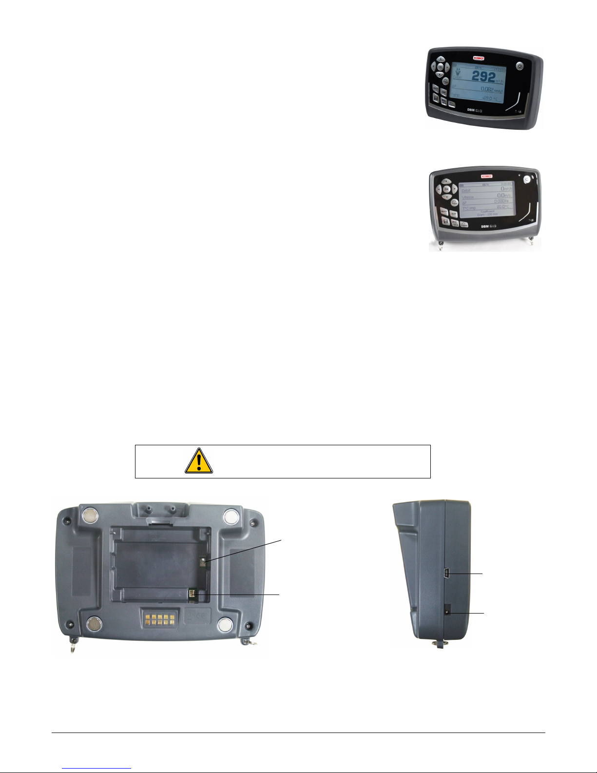
2.3. Electronic housing..................................................................................................................................................... 7
Features:......................................................................................................................................................................... 7
2.3.1. Airflow meter mode........................................................................................................................................... 8
2.3.2. Micromanometer mode..................................................................................................................................... 8
2.3.3. Power supply of electronic housing................................................................................................................... 8
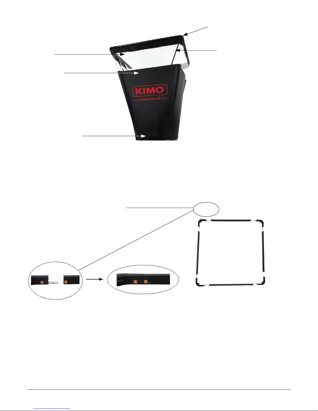
2.4. Hoods........................................................................................................................................................................ 9
3. Mounting the airflow meter................................................................................................................................................ 9
3.1. Mounting of frame..................................................................................................................................................... 9
3.2. Setting of the cloth.................................................................................................................................................. 10
3.3. Setting of rods......................................................................................................................................................... 11
4. Using D M610 in airflow meter mode............................................................................................................................. 12
4.1. Starting up............................................................................................................................................................... 12
4.2. Configure the airflow meter..................................................................................................................................... 12
4.2.1. Set the correction coefficient........................................................................................................................... 12
4.2.2. Set measurement units................................................................................................................................... 12
4.2.3. Set a damping................................................................................................................................................. 12
4.2.4. Activate or deactivate standardised airflow..................................................................................................... 12
4.3. Perform averages.................................................................................................................................................... 13
4.3.1. Perform an automatic average........................................................................................................................ 13
4.3.2. Perform an aggregate of automatic averages................................................................................................. 13
5. Using D M610 in micromanometer mode...................................................................................................................... 14
5.1. Starting up............................................................................................................................................................... 14
5.2. Set the micromanometer......................................................................................................................................... 14
5.2.1. Select the airflow sensor................................................................................................................................. 14
5.2.2. Set the surface................................................................................................................................................ 14
5.2.3. Set measurement units................................................................................................................................... 15
5.2.4. Set a damping................................................................................................................................................. 15
5.2.5. Activate or deactivate the solenoid valve........................................................................................................ 15
5.2.6. Set the thermocouple type.............................................................................................................................. 15
5.2.7. Set the compensation temperature................................................................................................................. 16
5.2.8. Activate or deactivate the standardised airflow............................................................................................... 16
5.3. Activate or deactivate air velocity and airflow.......................................................................................................... 16
5.4. Use the Matrix grid.................................................................................................................................................. 16
5.5. Perform averages.................................................................................................................................................... 16
5.5.1. Automatic average.......................................................................................................................................... 16
5.5.2. Point/point average......................................................................................................................................... 16
5.5.3. Point/point automatic average......................................................................................................................... 17
5.6. Perform an autozero............................................................................................................................................... 17
5.7. Hold the measurement............................................................................................................................................ 17
6. Manage dataset recordings............................................................................................................................................. 18
6.1. Get to recorded datasets......................................................................................................................................... 18
6.2. Delete recorded datasets........................................................................................................................................ 18
7. Set the device................................................................................................................................................................. 19
7.1. Set date and time.................................................................................................................................................... 19
7.2. Set language........................................................................................................................................................... 19
7.3. Set automatic shut-off............................................................................................................................................. 19
7.4. Set brightness......................................................................................................................................................... 19
7.5. Set contrast............................................................................................................................................................. 19
7.6. Activate or deactivate beep..................................................................................................................................... 19
8. Information about the device........................................................................................................................................... 20
8.1. Identification............................................................................................................................................................ 20
8.2. Calibration............................................................................................................................................................... 20
8.3. After sales service................................................................................................................................................... 20

1. Introduction
DBM610 airflow meter allows control and balancing of airflow in air conditioning system. Thanks to the interchangeable
hoods, the airflow can be used on any type of grids or diffusers in air supply or exhaust.
Easy to handle, lightweight, it allows accurate, sturdy and fast measurements.
t is supplied in standard with a 610 x 610 mm hood. Four other dimensions are available as options:
•1020 x 1020 mm
•720 x 720 mm
•720 x 1320 mm
•420 x 1520 mm
These hoods are airtight and have a transparent part on each side, allowing the user to see through the vent and
ensure that the hood is in a good position. The rods, made of fibreglass, provide a sturdiness of hoods.
The measurement grid, attached to the base, allows the measurement through 48 points all over the surface of the
grid. Measurement is performed using a differential pressure sensor, calibrated and compensated in atmospheric
pressure and temperature.
The measuring unit of the airflow meter, removable, can be used as a micromanometer
Real addition to airflow measurement, this instrument allows, by connecting a Pitot tube, to measure airflow velocity in air
duct or, by connecting two silicone tubes, to check filter fouling of air station. t is also possible to connect the matrix grid
designed for air velocity measurements on any types of large celling vent or diffuser. This grid calculates the average air
velocity from 24 points to guarantee a reliable measurement.
1.1. Key points
•Measuring range from 40 to 3500 m3/h
•Quick and simple hood changes
•Software for data processing on computer (datalogger 10)
•Sturdy, lightweight and easy to handle
•Removable measuring unit
•Interchangeable hoods
1.2. Technical features
•Airflow:
Measuring range: from 40 to +3500 m3/h
Accuracy: 3% of measuring ±10 m3/h
Resolution: 1 m3/h
•Air velocity:
Measuring range: from 0.2 to 10 m/s
Accuracy: 3% of measuring ±0.04 m/s
Resolution: 0.01 m/s up to 3 m/s and 0.1 m/s beyond
•Temperature (on the base)
Measuring range: from 0 to 50°C
Accuracy: 2% of measuring ±0.1°C
Resolution: 0.1°C
•Thermocouple Temperature (on the micromanometer)
Thermocouple type: K, J, T, S
Measuring range: K: from -200 to 1300°C
J: from -100 to 750°C
T: from -200 àto400°C
S: from 0 to 1760°C
4Introduction

Accuracy: K, J, T: from -200 to 0 °C: ±0.4°C ±0.3% of reading
from 0 to 1300 °C: ±0.4°C
S: ±0.6°C
Resolution: 0.1°C
•Pressure:
Measuring range: from -2500 to +2500 Pa
Accuracy: ±0.2% of measuring ±2 Pa
Resolution: from 0.001 to 0.1 Pa
Tolerated overpressure: 34473 Pa
1.3. General technical features
Display Large graphic back-lighted LCD / Sizes: 86 x 51 mm
Connectors ABS connectors, Ø 7 x 4 mm
Storage capacity 200 datasets of 100 points
Housing Shock-proof made of ABS, P54 protection
Keypad 12 keys
Conformity Electromagnetical compatibility (NF EN 61326-1 guideline)
Power supply 4 alkaline batteries LR6
Rechargeable battery Li-ion 3.7 V 4400 mhA (optional)
Environment Neutral gases
Operating temperature From 0 to +60 °C
Storage temperature From -20 to +70 °C
Auto-shut-off Adjustable from 0 to 120 min
Weight 3600 g
Languages French, English, German, Finnish, Dutch, talian, Norwegian, Portuguese, Slovak,
Swedish, Chinese
Introduction 5

2. Presentation of airflow meter
2.1. Base
•Outside of the base:
•nside the base:
6Presentation of airflow meter
Carrying handle
Protective cover Location for the
electronic housing
Integrated ergonomic handle
Button of point/point
measurement start
Electronic card
Silicone tube for pressure
routing
Receipt cup hood rods Measurement grid
Temperature probe
Two pressure connectors

2.2. Grid
The measurement grid is fixed to the base in 6 points and is made up of the following elements:
•two chambers (for total pressure and for static pressure)
•2 pressure connectors
The measurement grid allows to measure differential pressure. t takes into account atmospheric pressure and temperature
compensation and works automatically in supply or exhaust.
2.3. Electronic housing
Features:
•Shock-proof made of ABS
•P54 protection
•Large graphic back-lighted LCD (86 x 51 mm)
•Auto shut-off adjustable from 0 to 120 min
•Manual or automatic autozero
•Removable housing for micromanometer function
•4 magnets at the back allow the mounting on the base (airflow meter mode)
•2 pressure plugs allow to set the housing on the base and the connection of silicone tube for the measurement with
a Pitot tube
•1 thermocouple plug on the top of the housing (micromanometer mode)
Presentation of airflow meter 7
2 pressure
connectors
Validation button
Front side
On/Off button
Save button
Average button
Autozero button
Hold button
Menu button
Escape button
Low battery signal
Back side
Pressure plugs
Magnet
Thermocouple
plug
Battery trap

2.3.1. Airflow meter mode
n airflow meter mode, the device has following functions:
•Simultaneous display of airflow, pressure and temperature
•Automatic airflow direction (supply or exhaust)
•Automatic average and point by point average
•HOLD function (measurement is fixed)
•USB interface for PC operation
•Languages choice
2.3.2. Micromanometer mode
n micromanometer mode, the device has following functions:
•Measurement of air velocity with Pitot tube S, L or Debimo blades
•Measurement of thermocouple temperature
•Automatic average and point by point average
•HOLD function (measurement is fixed)
•USB interface for PC operation
•Languages choice
2.3.3. Power supply of electronic housing
The airflow meter is supplied in standard with 4 batteries type AA LR6 1.5V. Rechargeable batteries and Li- on battery are
available as options.
To replace batteries (rechargeable or not):
➢Remove the batteries cover then used batteries.
➢Disconnect the batteries support.
➢Replace batteries then reconnect the support.
➢Replace the batteries cover.
To put the Li-Ion battery (optional):
➢Remove the batteries cover then the batteries support.
➢Connect the battery.
➢Replace the batteries cover.
To load the device:
•f the device is on Li- on battery: connect the main adapter/charger on the side of the device
•f the device is on rechargeable batteries: remove batteries load them an external charger
t is also possible to load the electronic housing with the main adapter/charger supplied with Li- on battery.
8Presentation of airflow meter
Respect the connections (see below)
Connection for LR6 batteries
support (rechargeable or not)
Connection for
Li-Ion battery
Back view Side view
Connection for
main
adapter/charger
USB connection

2.4. Hoods
3. Mounting the airflow meter
3.1. Mounting of frame
To mount the different optional frames of airflow meter, just fit together the elements of the frame.
Stickers numbered from 1 to 8 are stuck on each end of the elements:
Example with 720 x 720 mm frame:
Mounting the airflow meter 9
Transparent mica allowing a good
visibility and making easy the position
of the hood
Elastic to hold the hood on
the base
Frame with a foam to ensure a
good airtight with ceiling
Frame rods
Step 1
Cloth of the hood
1122
3
3
4
4
5 566
7
7
8
8

3.2. etting of the cloth
Before set the cloth on the frame, frame must be mounted.
➢First, insert a corner of the frame inside a corner of the cloth.
➢nsert the opposite corner of the frame in the corresponding corner of the cloth.
The colour mark must be in the middle of the frame side. (1).
➢Press on the corresponding side of the cloth to put it in the rail of the frame.
➢Proceed the same way for the rest of the cloth.
When the cloth is fixed on the frame:
➢Place the cloth on the base.
The mark on the cloth and the Velcro tape are opposed to the carrying handle of the base.
➢Put the elastic of the cloth around the DBM base.
➢Tighten the Velcro tape of the cloth on the base.
➢f necessary, turn the cloth to match the mark of the cloth with the mark on the base.
10 Mounting the airflow meter
Zoom on the back of the
base with tightened Velcro
tape
Elastic to be set
around the base
Mark on the cloth Mark on the
base
Cloth on the base
1

3.3. etting of rods
➢Maintain the hood with the base and put the four rods inside.
➢Take a rod and insert the rounded end of the rod in the reception holding cup of the base.
➢Slightly bend the rod and insert the flat end of the rod on the opposite corner of the holding cup. The crossing rods
must be on the same plan as the K MO logo.
➢Proceed the same way for the three other rods.
For the 1020 x 1020 mm, 1320 x 720 mm and 1520 x 420 mm length frames, the
plastic supple protections on the hood must be positioned in front of the cups on the
frame.
Mounting the airflow meter 11
Rounded end in the
holding cup
Rounded end in
the holding cup
Flat end in the
opposite corner
Rod
Flat end Rounded end

4. Using DBM610 in airflow meter mode
4.1. tarting up
When the airflow meter is correctly set and the housing mounted on the base,
press On/Off button:
The device directly displays the data belo (see photo):
•airflow
•delta pressure
•temperature
The solenoid valve is active and flaps every second.
4.2. Configure the airflow meter
➢Press "Menu".
➢Press "Left arrow" or "Right arrow" key until reach "Configuration".
➢Press "OK".
The sub-menu "Configuration" appears ith follo ing data:
•Correction coefficient: allows to set the correction coefficient
•Units: allows to set unit for airflow, pressure and temperature
•Damping: allows to smooth the measurement and avoid unwanted
•Standard airflow: allows to activate or not the standardized airflow as per D N1343 standard
4.2.1. Set the correction coefficient
➢Go to "Correction coef" line then press OK.
➢Select the required correction coefficient with up and down arrows then press OK.
Screen displays the selected coefficient. It is possible to modify it ith arro keys.
➢Press OK to validate and back to "Configuration" menu.
4.2.2. Set measurement units
➢Go to "Unit" line then press OK.
➢Go to the required line (airflow, temperature or pressure) then press OK.
➢Select unit with up and down arrows then press OK.
Available units are:
•Airflow: m3/h, L/s, cfm
•Pressure: Pa, mmH2O, mmHg, inWg
•Temperature: °C, °F
➢Press Esc to quit "Units" sub-menu and back to "Configuration" menu.
4.2.3. Set a damping
➢Go to "Damping" line then press OK.
➢Select the required coefficient (from 0 to 9) then press OK.
4.2.4. Acti ate or deacti ate standardised airflow
The standardised airflow allows to have a calculation of airflow as per D N 1343 standard.
➢Go to "Standard airflow" then press OK
➢Select ON or OFF with up and down arrows then press OK.
When standardized airflo is activated, "NORMO" indication is sho n on screen on the left of time.
12 Using DBM61 in airflow meter mode

4.3. Perform averages
During measurement, it is possible to perform an automatic average. This automatic average is calculated on the basis of
one measurement each seconds. t is also possible to get an addition of several dataset of automatic average.
4.3.1. Perform an automatic a erage
➢Press "Moy/Avg".
➢Press OK or the red button on the right of the base to launch measurement.
Measurement duration appears at the lo er right of the screen.
➢Press OK or the red button on the right of the base to display the results when required measurement duration is
reached.
Screen displays the follo ing results in the left column:
•Average
•Minimum value
•Maximum value
•Deviation: standard deviation on all the measured values
➢Press up and down arrows to get to results of the different parameters.
➢Press “Save” to save the dataset.
Screen backs to the display of results ith:
•Left column: measurement results
•Right column: addition of averages on several datasets of automatic averages
Results displayed in both columns are identical because based on a single dataset.
4.3.2. Perform an aggregate of automatic a erages
Results of the aggregate of averages are based on several datasets of automatic average, it means that the DBM 610
should not be turn off and the “Esc” key should not be pressed.
Once a 1st dataset of automatic average has been realized and saved:
➢Press OK or the red button on the right of the base to go to measurement screen.
➢Press OK again or the red button on the right of the base to launch a new measurement.
➢Press OK again or the red button on the right of the base to display results when required measurement duration is
reached.
➢Press up and down arrows to get to results of the different parameters.
Screen displays the follo ing results in the left column:
•Average
•Minimum value
•Maximum value
•Deviation: standard deviation on all the measured values
No result is displayed on the right column (Σ).
➢Press up and down arrows to get to results of the different parameters.
➢Press “Save” to save the dataset.
On measurement screen:
➢Press "Esc" to cancel and not include these results. t will be possible to launch a new measurement.
➢Press "Save" to save results.
Screen displays the follo ing results in the left column:
•Left column: measurement results
•Right column (Σ): aggregate of averages on several datasets of automatic averages
Using DBM61 in airflow meter mode 13

. Using DBM610 in micromanometer mode
5.1. tarting up
The device is disconnected from airflow meter base.
➢Press On/Off.
The device directly displays data belo (see photo):
•Airflow
•Air velocity
•Pressure delta
•Temperature compensation
•Type of airflow sensor used and size of the surface
5.2. et the micromanometer
➢Press "Menu".
➢Press "Left arrow" or "Right arrow" until reach "Configuration".
➢Press "OK" button.
The sub-menu "Configuration" appears ith follo ing data:
•Airflow sensor: allows to select the airflow sensor used for the measurement: Pitot tube L, S,
Debimo blade, Matrix grid or Coefficient
•Surface: allows to define the of surface and its size
•Units: allows to define unit for airflow, air velocity, pressure and temperature
•Damping: allows to smooth the measurement and avoid unwanted variations
•Solenoid valve: allows to activate or not the solenoid valve
•Thermocouple: allows to set the thermocouple type: K, J, T or S
•Temp Compen: allows to set the compensation temperature
•Standard airflow: allows to activate or not the standardized airflow as per D N1343 standard
5.2.1. Select the airflow sensor
➢Go to "Airflow sensor" line then press OK.
➢Press OK on the "Element" line.
➢Select the airflow sensor (Pitot tube L, Pitot tube S, Debimo blade, Matrix grid or Coefficient) with up arrow and
down arrow then press OK.
t is also possible to select the corresponding coefficient to the airflow sensor:
➢Go to "Airflow sensor" line then press OK.
➢Press OK on the "Coefficient".
➢Select the coefficient from 0 to 9 with up arrow and down arrow then press OK.
Screen displays the required coefficient. It is possible to modify it ith arro buttons.
➢Press OK to back to "Airflow sensor" sub-menu .
➢Press Esc to quit "Airflow sensor" sub-menu and back to "Configuration" menu.
5.2.2. Set the surface
Set length and width of the surface:
➢Go to "Surface" and press OK.
➢Go to "Type" line then press OK.
➢Press OK on “Lxl” line.
➢Select the required dimensions with up and down arrows then press OK.
➢f necessary, modify the length then the width with arrows then press OK (if no modification, just press OK).
Set diameter of the surface:
➢Go to "Surface" then press OK.
14 Using DBM61 in micromanometer mode

➢Go to "Type" line then press OK.
➢Press OK on “Diameter” line.
➢Select the required dimension with up and down arrows then press OK.
➢f necessary, modify the diameter with arrows then press OK (if no modification, just press OK).
Set surface unit:
➢Go to "Surface" then press OK.
➢Go to "Type" line then press OK.
➢Press OK on “Unit” line.
➢Select the unit (mm or in) with arrows then press OK.
Set K factor:
The air flow in a ventilation opening, Qv (m³/h), can be evaluated from a differential pressure measurement on this
ventilation opening, ΔP (Pa). The K factor is a coefficient used to measure the volumetric flow rate on an air vent. This
coefficient is given in the technical features of the air vent.
f the coefficient is not specified in the air vent technical document or directly on the air vent, please request
the manufacturer to know this coefficient.
From the air vent coefficient, named K, it is possible to calculate the volumetric flow rate:
Qv=K×
√
ΔP
➢Go to "Surface" then press OK.
➢Go to "K factor" line then press OK.
➢Select the K factor with up and down arrows then press OK.
➢f necessary, modify the value of K factor with arrows then press OK (if no modification, just press OK).
➢Press Esc to quit "Surface" sub-menu and back to "Configuration" menu.
5.2.3. Set measurement units
➢Go to "Units" line then press OK.
➢Go to the required line (airflow, air velocity, pressure or temperature) then press OK.
Available units are:
•Airflow: m3/h, L/s, cfm
•Air velocity: m/s, fpm, km/h, mph
•Pressure: Pa, mmH2O, mmHg, inWg
•Temperature: °C, °F
➢Press Esc to quit "Units" sub-menu and back "Configuration" menu.
5.2.4. Set a damping
➢Go to "Damping" line then press OK.
➢Select the required coefficient (from 0 to 9) then press OK.
5.2.5. Acti ate or deacti ate the solenoid al e
➢Go to "Solenoid valve" line then press OK
➢Select ON or OFF with up and down arrows then press OK.
5.2.6. Set the thermocouple type
➢Go to "Thermocouple" line then press OK
➢Select thermocouple type: K, J, T or S with up and down arrows then press OK.
Using DBM61 in micromanometer mode 15

5.2.7. Set the compensation temperature
➢Go to "Temp Compens" line then press OK
➢Set the temperature with arrows then press OK This temperature must be between -20 and 80°C
5.2.8. Acti ate or deacti ate the standardised airflow
The standardised airflow allows to have a calculation of airflow as per D N 1343 standard.
➢Go to "Standard airflow" line then press OK
➢Select ON or OFF with up and down arrows then press OK.
When standardised airflo is activated, "NORMO" indication is sho n on screen on the left of time.
5.3. Activate or deactivate air velocity and airflow
t is possible to activate or deactivate measurement in air velocity and/or airflow.
➢Press "Menu".
➢Go to "Measurement" with left and right arrows then press OK.
➢Go to "Airflow" or "Air velocity" then press OK.
➢Select ON or OFF then press OK.
5.4. Use the Matrix grid
The Matrix grid is designed for the air velocity measurement on any types of celling vents or diffusers with a large useful
area.
To use the DBM610 in Matrix grid mode, place the grid on the telescopic pole and add the positioning struts that will be
against the celling. Struts are available in 3 different lengths:
•3 x 5 cm
•3 x 15 cm
•3 x 25 cm
These struts allow to remain parallel to the celling. The length of the struts allow to be more or less distant from the celling,
it can be useful in case of high air velocity. ndeed, the air velocity decreases as soon as we keep away from the celling
vent.
To connect the silicone tubes:
➢Ensure that each silicone tube is connected correctly. For example, the white one connected on the “+” sign of the
micromanometer and on the “+” sign of the Matrix grid and the black one connected on the “-” sign of the
micromanometer and on the “-” sign of the Matrix grid
5.5. Perform averages
The micromanometer can perform 3 types of averages: automatic average, point/point average and automatic point/point
average.
➢Press "Moy/Avg" button.
➢Select the type of required average then press OK.
5.5.1. Automatic a erage
This function allo s the calculation of the average value measured by the device in a selected time interval.
First, select "Auto average", the device displays measurement screen.
➢Press OK to launch measurement
The device displays measured values and measurement duration.
➢Press OK to stop measurements and get results.
➢Press up and down arrows to get to results of different parameters.
➢Press "Save" button to save dataset or Esc to cancel and back to measurement screen.
5.5.2. Point/point a erage
16 Using DBM61 in micromanometer mode

This function allo s the calculation of the average bet een different measurement points selected by the user.
First, select "Pt/Pt average", the device displays measurement screen.
➢Press OK to validate the 1st point.
The device displays measured values and the number of measurement points.
➢Press OK to add measurement points.
➢Press "Moy/Avg" button to get to screen results when the required number measurement points has been
reached.
➢Press up and down arrows to get to results of different parameters.
➢Press "Save" to save dataset or Esc to cancel and back to measurement screen.
5.5.3. Point/point automatic a erage
This function allo s the calculation of average value of different measurement points hich are calculated on a given
duration. It is necessary to give the duration hile each point ill be calculated.
First, select "Auto Pt/Pt average", the device displays measurement screen.
➢Press OK to validate the 1st point.
➢Enter the duration in minute and second with arrows then press OK.
➢Press OK to launch the measurement of the 1st point.
The device displays measurements and the remaining measurement duration.
➢Press OK to add measurement points.
➢Press "Moy/Avg" button to get to screen results when the required number measurement points has been reached.
➢Press up and down arrows to get to results of different parameters.
➢Press "Save" to save dataset or Esc to cancel and back to measurement screen.
5.6. Perform an autozero
The autozero allows to offset from time to time any drift of the sensitive element during time by a manual adjustment of the
zero. The autozero is made automatically when the solenoid valve is activated.
➢Press "Zero" during measurement.
5.7. Hold the measurement
During the measurement, the “Hold” function key of the device allows to fix the measurement:
➢Press the “Hold” function key.
The current measurement is fixed. The “HOLD” indication is displayed on the top of the screen.
➢To fix a second measurement value, press again the “Hold” function key.
The device displays both of the fixed values: on the right the first value and on the left the second value.
➢Press “Hold” to restore the display of the first value only.
➢Press “Esc” to quit the “Hold” mode.
The device displays the current measured values.
Using DBM61 in micromanometer mode 17

6. Manage dataset recordings
This part allows to display or delete recorded dataset in the device.
To get to dataset from "Measurement "screen:
➢Press "Menu" or "Save" button.
➢Go to "Savings" with left and right arrows.
➢Press OK.
6.1. Get to recorded datasets
➢Go to "Display" line then press OK.
Dataset list is displayed.
➢Go to the required dataset then press OK.
Dataset opens ith follo ing features:
•Number of points
•Dataset type
•Date and time of beginning and end
➢Press OK to display values.
Values table opens.
➢Use left and right arrows to change of page.
➢Use up and down arrows to change parameters.
➢Press Esc to back to the recorded dataset list.
6.2. Delete recorded datasets
➢Press "Delete" line then press OK.
A message is displayed asking to all erase.
➢Press OK to all erase or Esc to cancel.
18
Totality of recordings will be definitively deleted

7. Set the device
This part allows to set the different general parameters of the device.
➢Go to "Menu".
➢Go to "Settings" with left and right arrows.
➢Press OK.
7.1. et date and time
➢Go to "Date/Time" line then press OK.
➢Set date and time with arrows.
➢Press OK to validate and back to "Settings" sub-menu.
7.2. et language
➢Go to "Languages" line then press OK.
➢Select the required language (French or English) with up and down arrows.
➢Press OK to validate.
7.3. et automatic shut-off
➢Go to "Extinction" line then press OK.
➢Select OFF to deactivate it or the time before automatic shut-off (15, 30, 45 min or 1h).
➢Press OK to validate.
7.4. et brightness
➢Go to "Brightness" line then press OK.
➢Select the required level of brightness (from 1 to 9 or AUTO) with up and down arrows.
➢Press OK to validate.
7.5. et contrast
➢Go to "Contrast" line then press OK .
➢Select the required level of contrast (from 0 to 3) with up and down arrows.
➢Press OK to validate.
7.6. Activate or deactivate beep
➢Go to "Beep" line then press OK.
➢Select ON to activate or OFF to deactivate beep of the keyboard of device
➢Press OK to validate.
Set the device 19

8. Information about the device
This part allows to have any information about identification, calibration and after sales service.
To get to it from measurement screen:
➢Press "Menu".
➢Go to "Informations" with left and right arrows.
8.1. Identification
➢Go to "Identification" then press OK.
Screen displays soft are version number and device serial number.
➢Press Esc to back to "Informations" menu.
8.2. Calibration
➢Go to "Calibration" then press OK.
Screen displays calibration date of the device.
➢Press Esc to back to "Informations" menu.
8.3. After sales service
➢Go to "After sales service" then press OK.
Screen displays Kimo after sales services phone number and email.
➢Press Esc to back to "Informations" menu.
20 Information about the device
Other manuals for DBM610
1
Table of contents
Other Kimo Measuring Instrument manuals