SEAL Image 410 Instructions for use

Image®410 Laminator
Owners Manual
Image®410 Laminator
Owner’s
Operation
Manual

2
TABLE OF CONTENTS
TABLE OF CONTENTS...................................................................................................................................................................2
INTRODUCTION................................................................................................................................................................................3
WORKSPACE / ELECTRICAL REQUIREMENTS.............................................................................................................4
ENVIRONMENT CONDITIONS................................................................................................................................................5
UNPACKING, SET-UP AND INSTALLATION....................................................................................................................6
IMPORTANT SAFEGUARDS.........................................................................................................................................................8
SAFETY FEATURES...........................................................................................................................................................................9
LAMINATOR FEATURES................................................................................................................................................................10
CONTROL PANEL.............................................................................................................................................................................11
PRESET PROGRAMS..........................................................................................................................................................................13
CHECKING OPERATION..............................................................................................................................................................14
SET-UP AND OPERATION............................................................................................................................................................15
WEBBING FILMS WITHOUT A RELEASE LINER............................................................................................................17
WEBBING FILMS WITH A RELEASE LINER.......................................................................................................................18
DECALING (HEAT-ACTIVATED).............................................................................................................................................19
DECALING (PRESSURE-SENSITIVE).....................................................................................................................................20
MOUNTING...........................................................................................................................................................................................21
ONE STEP MOUNTING AND LAMINATING...................................................................................................................22
ENCAPSULATING..............................................................................................................................................................................23
PRE-COATING BOARDS................................................................................................................................................................24
APPLYING AN OVERLAMINATE.............................................................................................................................................25
PROCESS CONTROL SHEET........................................................................................................................................................26
CLEANING / MAINTAINING YOUR LAMINATOR......................................................................................................27
PERIODIC MAINTENANCE SHEET........................................................................................................................................28
ERROR CODES.....................................................................................................................................................................................29
TROUBLESHOOTING GUIDE....................................................................................................................................................30
GLOSSARY OF TERMS.....................................................................................................................................................................32
SPARE PARTS LIST..............................................................................................................................................................................33
TECHNICAL SPECIFICATIONS..................................................................................................................................................34
LIMITED WARRANTY......................................................................................................................................................................35

3
INTRODUCTION
Thank you for purchasing a SEAL®Image®410
Laminator. We have designed the SEAL Image 410 to
give you years of reliable service. The Image 410 brings
a new level of simplicity and ease of use to image
finishing.
As you become familiar with your laminator, you will
appreciate the high quality of its production and the
excellence in its engineering design.
By following the guidelines for proper care and use of
the SEAL Image410, you can depend on many years of
trouble-free profitability from your investment.
The purpose of this manual is to outline the materials
and process when using SEAL Brands supplies with
your laminator to create signs, displays, and flexible
graphics with professional results. The manual includes
instructions of various laminating procedures, which are
meant to give you comprehensive information needed
for the efficient use of your laminator.
Please read and fully understand the entire manual
before proceeding to use your laminator.
STATEMENT OF INTENDED USE
Your SEAL Image 410 Laminator meets the CE
Machinery Safety Directive and is ETL approved.
The SEAL Image410 laminator has been designed to be
used with SEAL Brands materials. When used with
these products, you are able to mount, mount and
laminate, and encapsulate prints in one step. Your
laminator has been tested with SEAL Brands supplies
and we recommend using these products for
professional results.
WARNING! This laminator is designed for
mounting and laminating. Any use other than the
intended may cause damage to the laminator or
physical harm to the user.
WARNING! Any unauthorized changes or
modifications to this unit without our prior written
approval will void the user’s warranty and will
transfer health and safety obligations to the user.
LIABILITY STATEMENT
The details given in this manual are based on the most
recent information available to us. They may be subject
to change in the future. We retain the right to make
changes to the construction or the design of our
products without accepting any responsibility for
modifying earlier versions previously delivered.
CAUTION! Please pay attention to all passages
marked this way. This information is vital to
preventing user injury and/or damage to the unit.
Failure to follow this information could void the
user’s warranties and transfer all safety obligations
to the user.

4
WORKSPACE / ELECTRICAL REQUIREMENTS
•Keep the area around your laminator clear with
adequate space around it so you can feed, receive
and trim mounted and/or laminated images.
•An area 11’ x 11’ (3.4m x 3.4m) is the smallest area
recommended. We recommend a room size of 20’x
18’ (6.1m x 5.49m) to accommodate a laminator and
2 (4’ x 8’) tables on castors for finishing/layout
work. This area is required for loading and unloading
rolls of material onto the unwind shafts and feeding
and receiving the maximum mounting board lengths
into the laminator correctly.
•NOTE: Maximum board lengths are up to 12 feet
long.
•The work area should be level, flat, and well lit.
CONNECTING YOUR LAMINATOR
Connect the laminator in accordance with the details
given on the identification plate (Serial Number Label)
attached to the left stand leg of the laminator. Refer also
to the Technical Specifications page for more
information.
IMPORTANT! SEAL Graphics recommends that a
licensed electrician in accordance with electrical
codes in your area install your mains power or the
warranty will be void. Specifications subject to
change without notice.
We recommend the installation of a Ground Fault
Interrupter (GFI) circuit breaker if operating the
laminator near water or in an area of high humidity.
43"/110 cm
Maximum board length
30"/76 cm
Minimum Room Width =11 feet / 3.4 meter
Minimum Room Length = 11 feet / 3.4 meter
Rolls of Media
26"/66cm
UnwindShaft
Figure 1. Workspace Area Diagram

5
ENVIRONMENT CONDITIONS
The following environmental conditions are ideal for
the best operation of the laminator.
AMBIENT TEMPERATURE
The best temperature for the SEAL®Image®410 is
between 50°F and 86°F (16°C and 30°C).
Do not expose the laminator to direct sunlight as output
quality may be affected.
RELATIVE HUMIDITY
For best results, the ambient relative humidity for the
SEAL Image410 should be between 70-90% non-
condensing. Too much humidity will affect the prints
being laminated causing problems with film adhesion.
WATER AND MOISTURE
If the laminator is installed in a damp room or near
water, the electrical power supply must be in accordance
with the standards prevailing in the country concerned.
SURROUNDINGS
Install the laminator in surroundings that are as clean
and dust free as possible in order to obtain the highest
quality output.
The background dust level must not exceed that found
in a typical office/computer room environment.
The materials that are used on this laminator can have
an electrostatic charge and will attract dust, adversely
affecting the output.
POWER SUPPLY
Connect the laminator in accordance with the details
given on the Serial Number Label attached to the left
stand leg of the laminator. Refer also to the Technical
Specifications page for more information.
Once power is connected to your laminator, press the
Main Power Stand-by button on the control panel to
turn the laminator ON. If you have no displays, refer to
the “Troubleshooting” page for problem solving
information.
Identification Plate
Figure 2. Serial Number Label Location Diagram

6
ACCESSORIES INCLUDED:
•2-1/2 Square Cap for Stand Legs (4)
•Velcro, Black (to secure caps to stand legs)
•Snitty Safety Knife
•Image Roll Cleaner
•Roll Cleaning Towel
•Owner’s Manual
UNPACKING, SET-UP AND INSTALLATION
ONLY SKILLED PERSONNEL SHOULD PERFORM
INSTALLATION. READ AND COMPLY WITH ALL
WARNINGS AND FOLLOWTHE PROPER
INSTALLATION PROCEDURES AND SAFETY
GUIDELINES.
•Take into account the weight of the laminator (570-
lb./258 kg shipping weight) when moving. Use
equipment with which the weight can be safely
lifted. The laminator is transported on a wooden
pallet (skid). If your laminator is still on its skid, you
can move it with a forklift to put it near its place of
use.
IMPORTANT! Set the forks of the forklift to
the maximum lifting width of the laminator, so
the laminator’s center of gravity is central
between the forks.
•NOTE: We recommend that you save the transport
bolts, nuts and plates of the shipping crate for any
major moves that you plan to make with the
laminator in the future.
•Remove the transport bolts from the skid’s
transport plates with an open-end wrench or
adjustable wrench. Using the wrench, back the bolt
up enough to clear the cabinet castors for ease in
moving.
•Your laminator has castors to allow for easy
moving. Roll the laminator to the location it will be
used. (See Workspace Area Diagram –Figure 1).
•Lock the castors once it is in place and remember to
unlock them before moving the laminator again.
Figure 3. Moving the laminator with a forklift.

7
UNPACKING YOUR LAMINATOR
•Remove the transport packing and the plastic
shrink-wrap the laminator is wrapped in to avoid
moisture penetration.
•Remove the accessory kit package from the top of
the laminator, which includes the necessary tools
for installation.
•Remove the footswitch from the top of the
laminator and remove the foam wrapped around it.
•Place the footswitch in a position that is accessible
while feeding images.
•Remove the protective foam wrapped around the
front table.
•Remove the cardboard box containing the wind-up
idler and remove the wind-up idler from the box.
•Install the Wind-up Idler into place on the front
Wind-up Assemblies.
•Cut and remove the tie straps securing the Unwind
Shafts and remove the foam wrap from the ends.
•The top roller will go up automatically when power
is connected.
•Remove the blocks placed between the top and
bottom roller ends.
•Remove the stickers securing the protective paper
on the rolls using your fingers only.
•Then gently pull the paper towards you to unwind
off the roll.
WARNING! DO NOT USE OPEN BLADES
TO REMOVE THE PROTECTIVE PAPER
ON THE ROLLERS.
•Roller damage caused by improper use of cutting
tools will void the user’s warranty. Small cuts and
imperfections in the rollers greatly affect the quality
of the output and roller replacement costs are
expensive.
LEVELING YOUR LAMINATOR
•Use the open-end or adjustable wrench to turn the
transport bolts down until the bolts are positioned
flat against the floor.
•Insert a 3’ x 1’ (91cm x 30cm) piece of foam board
across the center of the laminator lengthwise
between the top roller and the back table and place
the level in the center on top of this foam board.
•Adjust the leveling feet for each side cabinet until
level.
•Next, place the level sideways on the piece of foam
board and adjust the leveling feet from the front to
the rear of the cabinet as needed.

8
IMPORTANT SAFEGUARDS
SAFETY SYMBOLS USED ON THE
LAMINATOR
IMPORTANT! Read and make sure you
understand these safety and operating
guidelines.
ROTATING PARTS: RISK OF INJURY
CAUTION! Failure to use caution near rotating
rollers could result in physical injury. Be careful
that items such as loose clothing, long hair and
jewelry do not become entangled in rotating parts.
The laminator is equipped with photoelectric eyes to
prevent contact with the rotating rollers. Make sure that
these safety provisions are always in operation/installed.
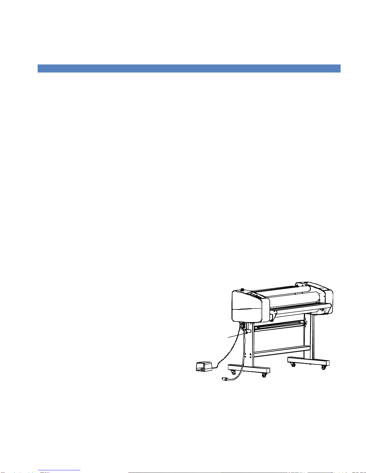
IMPORTANT! The laminator operation will cease
immediately when the photo electric eyes, set
directly in the path of the front of the rollers, are
blocked. On Domestic version laminators, the foot
switch overrides the photoelectric eyes. When the
photo eye is blocked, a BUZZER sounds, warning
of close proximity to the nip. Use care to keep
hands clear of the rollers while using the foot
switch to prevent possible injury.
HOT SURFACE: RISK OF INJURY ON
CONTACT
CAUTION! The laminator contains heated rollers,
which may reach temperatures of 250°F (121°C).
There is a danger of burns if the heated roller is
touched during use. Even after switching off the
laminator, the roller remains hot for a long time.
ELECTRICAL PARTS –DANGER OF BEING
INJURED BY ELECTRICITY
WARNING! Do not remove the side plate covers
because of the risk of being injured by voltage.
Only authorized maintenance and service
technicians or safety personnel should do this for
mechanical upkeep or repair.
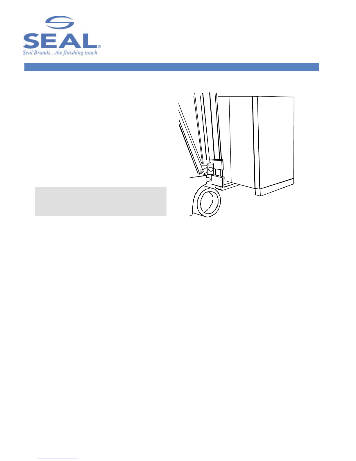
WARNING! Make sure the power disconnect
located on the left side stand leg is turned to the
OFF position before removing the side plate covers
for any maintenance.
IMPORTANT! Do not place heavy objects on the
power supply cord.
PREVENTATIVE MEASURES:
Do not feed objects such as staples, paper clips and
rough or abrasive materials through the laminating
rollers.
Keep all objects, such as tools, rulers, pens, markers or
knives away from the roller opening. Refrain from
leaving such items on the front table to prevent them
from accidentally being fed into the rollers.
IMPORTANT! NEVER cut or slice directly on the
rollers as any cuts or gouges will destroy them.
ALWAYS use cutters with enclosed blades to
prevent cutting the rollers and to avoid extensive
replacement costs.
WARNING! Always adjust the nip setting to create
a gap between the laminating rollers to prevent flat
spots from developing when the laminator is not in
use. Flat spots will affect the quality of the output
and void the warranty replacement.
IMPORTANT! The main roller should be together
and turning while heating up to prevent uneven hot
spots on the roller. A stationary roller will develop
concentrated heat in one area, which will damage
the roller. Pivot the front table away from the
heated roller when not in use to prevent possible
warping and voiding the warranty replacement.
SERVICING AND REPLACEMENT PARTS
Service and maintenance must be performed fully in
accordance with the instructions. Servicing by any
unauthorized technician voids the warranty. The service
technician must use replacement parts specified by
SEAL®Graphics.
Service Technicians must perform safety checks
after completing any service or repairs to the
laminator.

9
SAFETY FEATURES
The SEAL®Image®410 Laminator is designed with
safety and protective devices with the user’s safety of
utmost consideration. However, following safe
operating guidelines is still the responsibility of the
operator.
POWER DISCONNECT SWITCH:
Located on the left stand leg (facing front of laminator),
it automatically shuts the laminator power off when the
power disconnect switch is turned to the OFF position.
WARNING! Authorized service technicians must
disconnect the power by using the power
disconnect switch before any servicing.
SIDE PLATE COVERS:
The Side Plate Covers house the inner workings of the
laminator that maintenance or safety personnel can
open only with an Allen wrench.
WARNING! Use of the inside of the Side Plate
Covers for storage may cause possible personal
injury and/or damage to the inner workings and
will void the warranty.
HAND-OPERATED EMERGENCY STOP BUTTONS:
Emergency Stop buttons are located on the top of each
of the side plate covers for easy access. Once pressed,
they immediately cease the laminator’s operation and
raise the top roller. Use these only in the case of an
emergency or you may damage an image during a
process.
NOTE: Once pressed, these buttons lock and must
be turned clockwise to reset.
After resetting the Emergency Stop button, you must
turn the main power and the heaters back on (if being
used), and press the Motor Button ON to begin
processing again.
NOTE: If the Emergency Stop is depressed, the
machine will default to Program 1 upon restart.
COVERED FOOT SWITCH:
The foot switch allows for complete user control when
initially feeding an image into the nip or for feeding a
delicate image through the rollers. The cover prevents
accidentally stepping on the foot switch and starting the
laminator.
WARNING! On Domestic version laminators the
foot switch overrides the photoelectric eyes. When
the photo eye is blocked, a Flashing Light and a
BUZZER sounds, warning of close proximity to the
nip. Use care to keep hands clear of the rollers
while using the foot switch to prevent possible
injury.
PHOTO ELECTRIC SAFETYEYES:
A light beam path set directly in front of the laminating
roller opening prevents foreign objects from passing
between the rollers. (The eyes are set for use at the
factory and checked by the service representative.)
If the photo-eye is blocked when lowering the top
roller, there will be an audible alarm and the top roller
will not move down. To allow the top roller to continue
movement, the operator must clear the nip and then
press the Nip Adjustment Button DOWN arrow. The
roller will proceed to lower to the desired setting.
NOTE! This function can only be overridden by
using the footswitch.
REVERSE BUTTON:
The Reverse Button allows the rollers to be reversed if
there is a wrap around the enclosed pull rollers. The
Reverse Mode is operational when the motor is Off and
the footswitch is used.
WARNING! Keep hands clear of the pull rollers’
nip when using the Reverse Button. This button
can only be used in conjunction with the footswitch
and while operating at a slow speed of 1 fpm
(.3mpm). The speed cannot be adjusted.

10
LAMINATOR FEATURES
Figure 4. Laminator Features
1. Digital Touch Pad Control Panel with LED indicators
•It allows the operator to use 9 preset heat and motor
speed settings to match film applications. The operator
can also customize these settings.
2. Nip Motor driven roller height adjustment
•Allows for accurate roller nip setting with no need for an
air compressor. Adjusts for the thickness of the material
to be processed. Nip Indicator Lights indicate which nip
setting the rolls are currently set at.
3. Emergency Stop Buttons (2)
•Located on top of each side plate cover which
immediately ceases the laminator’s operation and raises
the top roller.
4. Swing-out Auto-grip Unwind Shafts (2)
•Easy loading and positioning of materials. Suitable for
rolls wound onto a 3-inch ID core.
5. Integral Braking System
•A simple braking system with a Knurled Collar provides
the means of adjusting the brake tension for the filmsand
images. Fitted on both the autogrip unwind shafts.
6. High release Silicone Coating Covered Rollers
•Prevents adhesive build-up and allows for easier cleaning
7. Automatic Wind-up Idler
•Removable idler for winding up the release liner, finished
images or other laminate material. Located on the top
front of the laminator. Use with 3-inch ID spare cores.
8. Print Guide In-feed Table
•Table with print guide for flat, wrinkle-free feeding of
digital prints. Pivots down to allow for easier webbing.
Feeding images under the print guide, directly into the nip,
prevents the images from lifting up and interupting the
photoelectric eyes.
9. Flashing Warning Light
•When the using the footswitch, if the photo eye is
blocked, this Flashing Light and a BUZZER sounds,
warning of close proximity to the nip.
*** Covered Foot Switch
•Allows for complete user control when initially feeding in
an image.
*** Electric Heating Elements
•Provide for rapid, even heating to 250°F (121°C).
2
1
3
9
4
6
5
4
7
8
3

11
CONTROL PANEL
1. Nip Adjustment Button: Press the UP arrow once
to raise one setting. Press and hold to raise multiple
settings. Press the DOWN arrow once to lower one
setting. Press and hold to lower multiple settings.
2. Nip Indicator Lights (LEDs): Indicates which nip
setting the rolls are currently set at.
3. Main Power On/Off (Stand-by) Button: Press this
button to turn ON or OFF (put in Stand-by) the
laminator. In Standby, the laminator power is still
on, but all functions are disabled. If an Emergency
Stop is pressed this button must be pressed to
restart the laminator. The corresponding LED is lit
when the power is ON.
WARNING! Even when the power is Off, the
laminator is in Stand-by. Authorized Service
Technicians must unplug the laminator before
any servicing.
4. Program Enter Button: This button has two
functions.
•Function A: Loading Preset Program. Press and
release to load shown program.
•Function B. Programming a New Preset. First,
select the desired program (1-9) you are changing
the settings for. Next, set the heat and motor speeds
to how you want the program to recall them. Then,
push and hold the Program Enter button. The
display will go blank (approximately three seconds),
and then the program will appear on the display.
Release the button.
NOTE: After a program has been loaded, the
operator can still change heat and speed
settings with their respective up and down
arrows.
5. Program Select Button: Press Up or Down arrow
once to see current program settings. (Speed and
Temperature Readouts). Press and hold Up or
Down arrow to raise or lower preset program
number.
6. Program Readout: Indicates which program is
currently available.
Figure 5. Control Panel Diagram
1
2
3
10
14
8
4
6
7
5
9
15
11
12
13
16

12
7. Reverse Mode Button: Reverses the direction of the
roller rotation.
NOTE: The Reverse Mode Button may only be
used with the footswitch and when the motor is
OFF.
•To use the Reverse Mode: Press the Reverse Mode
Button, the corresponding LED will be lit.
Depress the footswitch to activate the reverse
roller rotation. The Motor LED will be lit
during operation.
NOTE: The rollers will reverse at 1 fpm
(.3mpm) and the speed cannot be adjusted.
•To return to Forward Mode: Push the Reverse
Mode button, while not depressing the footswitch.
The Reverse Mode LED will not be lit.
•Press the Motor On/Off Button, the Motor LED
will be lit.
8. Motor ON/OFF Button: Press UP to start the
roller rotation, the switch will be illuminated. Press
the switch DOWN to stop the roller rotation. In the
OFF position, the footswitch can be used for roller
rotation.
9. Motor Speed Adjustment Button: Press the
corresponding arrow to increase or decrease the
speed.
10. Motor Speed Readout: Indicates speed in feet or
meters per minute.
11. Top Roller Temperature ON/OFF Button: Turns
ON/OFF the top roller heater. The corresponding
LED is lit when the heater is ON.
12. Top Roller Temperature Adjust Button: Press either
arrow (up or down) once to see the temperature set
point. Press and hold the corresponding arrow to
raise or lower the roller temperature.
13. Top Roller Temperature Readout: Displays both the
set and actual temperature of the top roller.
14. Bottom Roller Temperature On/Off Button: Turns
On/Off the bottom roller heater. The
corresponding LED is lit when the heater is ON.
15. Bottom Roller Temperature Adjust Button: Press
either arrow (up or down) once to see the
temperature set point. Press and hold the
corresponding arrow to raise or lower the roller
temperature.
16. Bottom Roller Temperature Readout: Displays both
the set and actual temperature of the bottom roller.

13
PRESET PROGRAMS
Settings provided are for optimal performance
using the SEAL®Brands films listed.
Purchasers should individually determine, prior to
use, the suitability of each material for their specific
purposes.
NOTE: When using a preset program, the
temperature will automatically activate.
PROGRAM 1: FLEXIBLE DISPLAYS
(ENCAPSULATING)
Flexible displays are created by sealing a print between
two layers of laminate.
Top (Jet Guard®Crystal Matte) 200°F (95°C)
Bottom (Jet Guard®Gloss) 200°F (95°C)
Speed 3fpm (1mpm)
PROGRAM 2: POP-UP DISPLAYS
Pop-Up Displays are created by encapsulating a print
between a hot laminate and a hot backing film.
Top (Jet Guard®Deep Crystal) 195°F (90°C)
Bottom (Stoplight®220 or 370) 210°F (100°C)
Speed 3fpm (1mpm)
PROGRAM 3: RIGID INDOOR DISPLAYS (DECALING)
Rigid Indoor Displays are made by first creating a decal,
by applying a laminating film over the face of the print,
and a pressure sensitive adhesive to the back.
Top (Jet Guard®Crystal Matte) 205°F (95°C)
Bottom (Print Mount®)110°F (45°C)
Speed 3fpm (1mpm)
PROGRAM 4:RIGID BACKLIT DISPLAYS
Rigid Backlit Displays are created by face mounting an
image to clear acrylic using an optically clear pressure
sensitive adhesive. Use the laminator to coat the acrylic
and mount the print.
Top (Optimount®)140°F (60°C)
Bottom (NA) 110°F (45°C)
Speed 3fpm (1mpm)
PROGRAM 5: FLOOR GRAPHICS
Floor Graphics are made by first creating a decal. Apply
Floor Guard, a special non-slip durable laminating film,
to the face of the print and Floor Grip 1, a
permanent/removable pressure sensitive adhesive, to
the back. This can be done in one pass. Use a hand
roller or squeegee to apply the graphic to a clean
smooth floor.
Top (Floor Guard®)200°F (95°C)
Bottom (Floor Grip®)110°F (45°C)
Speed 3fpm (1mpm)
PROGRAM 6: RIGID DISPLAYS
Rigid Displays are created by sealing a printable laminate
onto a foam board or rigid substrate.
Top 230°F (110°C)
Bottom 110°F (45°C)
Speed 0.5-1.0fpm (0.2-0.3mpm
PROGRAM 7, 8, AND 9: OPEN
Top (Film) ___°F (__°C)
Bottom (Film) ___°F (__°C)
Speed __fpm (__mpm)

14
CHECKING OPERATION
After you are familiar with the control panel and its
functions, check all operations.
WARNING! If your laminator does not operate
correctly, contact Technical Service immediately.
CHECK THE MAIN POWER
•Press the Main Power Stand-by button once and the
temperature displays on the control panel should be
lit.
•If there is no power, refer to the Troubleshooting
Page.
CHECK THE EMERGENCY STOP BUTTONS
•Press one of the Emergency Stop Buttons and the
laminator will shut down.
•Rotate the Emergency Stop Button clockwise to
reset.
•Reset the Main Power Stand-by button (press once).
The Power Indicator Light should be lit.
•Repeat this procedure with both Emergency Stop
Buttons.
CHECKING THE ROLLERS
Your laminator has Nip Motor driven roller height
adjustment for a smooth, flat finish. Correct adjustment
of the pressure rollers’ height is essential for safe and
proper operation. Check this prior to every use.
Check the vertical movement of the top rollers as
follows:
•Press the Nip Adjustment UP arrow button once.
The top roller should rise smoothly and evenly on
both ends.
•Press the Nip Adjustment DOWN arrow button
once. The top roller should lower smoothly and
evenly on both ends.
IMPORTANT: The silicone covering of the rollers
is soft. Do not scratch the surface with a sharp
object or fingernail.
CHECK THE TEMPERATURE CONTROLS
•Press the Top Temperature On/Off Button once.
The Top Temperature Indicator Light should be lit.
•The corresponding temperature control readout will
display the ambient temperature.
•Press the Top Roller Temperature Adjust Button
UP arrow once to see the temperature set point.
•Press and hold the Top Roller Temperature Adjust
Button UP arrow to increase the temperature set
point. Watch the readout for 5 minutes to verify
that the temperature increases.
•Press and hold the Top Roller Temperature Adjust
Button DOWN arrow to decrease the temperature
set point. Watch the readout for 5 minutes to verify
that the temperature decreases.
•Press the Top Temperature On/Off Button once.
The Top Temperature Indicator Light should not
be lit.
•Repeat this procedure for the Bottom Temperature.
CHECK THE MOTOR AND FOOTSWITCH
•Push the Motor ON/OFF button once, the motor
indicator light will be illuminated and the rollers
should rotate in the forward direction.
•Press and hold the Motor Speed Adjustment Button
UP arrow and the speed of the rollers and display
readout should increase.
•Press and hold the Motor Speed Adjustment Button
DOWN arrow and the speed of the rollers and
display readout should decrease.
•Press the Motor ON/OFF button once and the
rollers should stop rotating.
•Press the footswitch and the rollers should rotate.
•Adjust the Motor Speed by pressing the respective
arrow of the Motor Speed Adjustment Button while
using the footswitch to verify that the speed
increases and decreases.

15
SET-UP AND OPERATION
TEMPERATURE SETTINGS
•Select the film(s) that you will use on the top (and
bottom) of the images.
•Check which temperature setting is recommended
for your SEAL®Brands material (see literature
enclosed in your material box).
•Refer to the Control Panel Diagram for information
on setting the temperature.
NOTE: If a process requires heat, turn ON the
heaters approximately 30 minutes before use to
ensure that the rollers are at the correct
operating temperature.
IMPORTANT! The main roller should be
down and turning to prevent uneven hot spots
on the roller. A stationary heated roller will
develop concentrated heat in one area, which
will damage the roller.
ROLLER NIP SETTINGS
Whenever you mount onto a board, etc., it is important
to adjust the rollers to create a gap nearly equal to the
thickness of the board being used. This is done so that
anything passing between the rollers will receive the
right amount of pressure.
Equivalent Press Measurements
Inches Metric (mm) Decimal
MAX 28.6 mm 1.125
125 mm 1.000
3/4 19 mm 0.75
1/2 13 mm 0.50
3/8 10 mm 0.375
1/4 6 mm 0.25
3/16 5 mm 0.1825
1/8 4 mm 0.125
1/16 2 mm 0.0625
000
HOW TO SET THE ROLLER NIP
•First, determine the thickness of the board that you
will use for mounting.
•Adjust the nip setting by pressing the UP or
DOWN arrow until the desired measurement
corresponds with the thickness of board being used.
•Lower the top roller once the nip setting is adjusted.
WARNING! Too much pressure can crush the
board being used and even damage the top and
bottom rollers. Normally, a press of .025”
(0.6mm) is sufficient.
Figure 6. Nip Adjustment Settings
BASIC STEPS TO FEEDING IMAGES
NOTE: For good results, the process requires
that the images be fed through correctly.
•Make sure the leading edge of each image is flat all
the way across or any wrinkles or creases in the
image will show when laminated –perhaps even
magnified.
•A straight leading edge will aid in feeding in the
image.
•Feed the image into the laminator ensuring that the
leading edge is parallel to the roller.
NOTE: Do not stop the motor while an image
is being finished as this can cause marks in the
output.

16
SETTING THE UNWIND BRAKE TENSION
IMPORTANT! The brake tension greatly
affects the smooth flow of the laminating film.
•Turning the unwind brake in a counter-clockwise
direction increases the braking tension applied on
the laminate.
•Turning the unwind brake in a clockwise direction
decreases the braking tension.
•The best setting for the unwind brake tension is
determined by the materials you are using and is
learned through experience.
Figure 7. Unwind Brake
LOADING A ROLL OF MATERIAL
IMPORTANT! Make sure to fully release brake
tension whenever changing a roll of film.
•Swing out the desired unwind shaft towards you
and slide a roll of material onto the unwind shaft.
Ensure that the rubber blocking cords are on the
top and bottom for easy loading.
IMPORTANT! Make certain that you place the
roll of film on the unwind shaft so that the
material will feed with the adhesive side facing
away from the rollers.
•Press the unwind shaft firmly back into the receiver
to prevent tension and tracking problems.
•Center the films on the unwind shafts. Measure the
distance from the face of the cabinet and the film
edges (not the cores) and adjust until they are equal.
IMPORTANT! The position of all films,
boards, rolls of media and cardboard cores for
wind-ups must be set central in the laminator to
ensure optimum quality and correct tracking.
Laminate Side
Adhesive Side
Figure 8. Loading Films on Unwinds
Stretch film tight
and align edges.
Figure 9. Aligning Films on Unwinds
•TIP! For alignment accuracy, pull a length of film
backward off the top unwind shaft until it drapes
over the film on the bottom unwind shaft. Make
sure the edges of both films line up.
•Now secure the films on the shafts by gripping the
shafts with one hand while rotating the rolls of
material with the other hand in the direction it will
be pulled off the unwind shafts. The rubber
blocking cords will catch on the inside of the
material core and hold the material secure on the
shaft.
•If material needs to be rotated, turn the shafts, not
the rolls of film otherwise the roll of film will no
longer be secure to the shaft.

17
WEBBING FILMS WITHOUT A RELEASE LINER
The following are the basic webbing procedures for
webbing films without a release liner:
•Select films slightly wider than the image to allow for
a border without film waste. A border of 1/8” to
1/4” (3-6mm) is adequate.
•Ensure the main roller’s temperatures are set
according to the recommendations of the laminates
being used (see literature enclosed in your material
box).
WARNING! The rollers should be together and
turning while heating up to provide even heat
distribution and prevent roller flat spots from
developing.
•Once the laminator reaches correct operating
temperature, stop the laminator and raise the top
roller.
•Pivot the front table down for easier webbing access.
•Load and center the films on top and bottom unwind
shafts with the dull adhesive side facing out and the
unwind brake tension released.
NOTE: Check if the film widths of the lower
and upper web are the same!
•TOP FILM: Pull the film down from the top unwind
shaft, and place it evenly over the face of the top
roller.
•BOTTOM FILM: Pull the film up from the bottom
unwind shaft and place it evenly over the top film
draped over the face of the top roller.
•The two films will then heat and stick together.
•Set the Nip Setting to 1/16” (2mm) to allow for the
thickness of a leader-board.
•FILMS INTO NIP: Use the leader-board to push the
film(s) into the main roller nip.
•Lower the top roller and use the foot switch to
advance the leader board through the nip.
NOTE: Keep the film under tension (holding
back on the film roll) to prevent the photoelectric
eyes being tripped.
•When the film reaches the chill shoe, cut off the
leader board.
WARNING! Do not use open blades to cut or
slice on the surface of the chill shoe. Small cuts
and scratches will affect the output quality.
•Using the footswitch, feed the film into the pull
rollers.
•Check at the rear of the laminator, making sure the
film does not wrap around the enclosed pull rollers.
•Raise the top roller and set the Nip Setting to ‘0’, then
lower the roller again.
•Return the in-feed table to its working position.
•Apply light unwind brake tension gradually on both
unwind shafts until there are no wrinkles in the film
as it goes into the nip
•Run the laminator for about 3 feet (1 meter), to work
out any wrinkles. If wrinkles persist, cut the film and
web the laminator again.
YOU ARE NOW READY TO FEED IMAGES!
Film Path
Media Path
Figure 10. Webbing films w/o Release Liners

18
WEBBING FILMS WITH A RELEASE LINER
The following are the basic webbing procedures for
webbing films with a release liner:
•Select films slightly wider than the image to allow for
a border without film waste. A border of 1/8” to
1/4” (3 -6mm) is adequate.
•Ensure the main roller’s temperatures are set
according to the recommendations of the laminates
being used.
•Once the laminator reaches operating temperature,
stop the laminator and raise the top roller.
•Pivot the front table down for easier webbing access.
•Load and center the films on top and bottom unwind
shafts with the dull adhesive side facing out and the
unwind brake tension released.
NOTE: Check if the film widths of the lower
and upper web are the same!
•TOP FILM: (film with a release liner) Pull the film
down from the top unwind shaft, and place it evenly
over the face of the top roller.
•RELEASE LINER: Place a spare core over the front
top wind-up idler. Separate the film from the release
liner. Attach the release liner to the spare core using a
piece of tape.
•BOTTOM FILM: Pull the film up from the bottom
unwind shaft and place it evenly over the top film
draped over the face of the top roller. The two films
will stick together.
•Set the Nip Setting to 1/16” (2mm) to allow for the
thickness of a leader-board.
•FILMS INTO NIP: Use the leader-board to push the
film(s) into the main roller nip.
•Lower the top roller and use the foot switch to
advance the leader board through the nip.
•NOTE: Keep the film under tension (holding back
on the film roll) to prevent the photoelectric eyes
being tripped.
•When the film reaches the chill shoe, cut off the
leader board.
WARNING! Do not use open blades to cut or
slice on the surface of the chill shoe. Small cuts
and scratches will affect the output quality.
•Using the footswitch, feed the film into the pull
rollers.
•Check at the rear of the laminator, making sure the
film does not wrap around the enclosed pull rollers.
•Raise the top roller and set the Nip Setting to ‘0’, then
lower the roller again.
•Return the in-feed table to its working position.
•Apply light unwind brake tension gradually on both
unwind shafts until there are no wrinkles in the film
as it goes into the nip
•Run the laminator for about 3 feet (1 meter), to work
out any wrinkles. If wrinkles persist, cut the film and
web the laminator again.
YOU ARE NOW READY TO FEED IMAGES!
Film Path
Media Path
Release Liner
Figure 11. Webbing films with Release Liners

19
DECALING (HEAT-ACTIVATED)
This process involves applying a hot film to the top and
a cold backing adhesive to the bottom of the graphic.
This process can be used to create self-adhesive images
for mounting down onto various substrates. After
performing this process, follow the Mounting
Instructions in the manual to apply the decal to a
substrate. It is important to follow the webbing
instructions for films specific for your location.
MEDIA: INK JET, ELECTROSTATIC AND
PHOTOGRAPHIC FILMS:
-- -- -- Top Unwind: Heat-activated Laminate 3 –5 Mil
_____ Bottom Unwind: Pressure-sensitive mounting
adhesive
LAMINATOR SETTINGS
CONTROL PANEL
Top Roller Temp 205-215°F (96-102°C)
Bottom Roller Temp OFF
Motor Speed Setting 3-5 FPM (1-1.5 MPM)
WEBBING SETTINGS
Web Tension Top: Medium
Web Tension Bottom: Light
Nip Setting: ‘0’
NOTE! When using Mounting Adhesive on the
back of images it is best to run over the back table.
Running the film through the pull rollers may cause
the backing to separate from the release liner.
NOTE! Web the top laminate following the basic
procedures for webbing films w/o a release liner.
Film Path
Media Path
Figure 12. Webbing for Decaling (Heat-activated
films)

20
DECALING (PRESSURE-SENSITIVE)
This process involves applying a cold pressure-sensitive
over-laminate to the top and a cold pressure-sensitive
mounting adhesive to the bottom of a graphic. If
desired, set the top roller’s temperature to 120°F
(49°C). Using heat-assist may improve the adhesive
bonding of the laminate. This process can be used to
create self-adhesive images for mounting down onto
various substrates. After performing this process, follow
the Mounting Instructions in the manual to apply the
decal to a substrate. It is important to follow the
webbing instructions for films specific for your location.
MEDIA: INK JET, ELECTROSTATIC, AND
PHOTOGRAPHIC
FILMS:
-- -- -- Top Unwind: Pressure-sensitive over-laminate
____ Bottom Unwind: Pressure-sensitive mounting
adhesive
LAMINATOR SETTINGS
CONTROL PANEL
Top Roller Temp: OFF or Heat-assist
Bottom Roller Temp: OFF
Motor Speed Setting: 3-5 FPM (1-1.5 MPM)
WEBBING SETTINGS
Web Tension Top: Light
Web Tension Bottom: Light
Nip Setting: ‘0’
NOTE: When using Mounting Adhesive on the
back of images it is best to run over the back table.
Running the film through the pull rollers may cause
the backing to separate from the release liner.
NOTE! Web the top laminate following the basic
procedures for webbing films with a release liner.
Film Path
Media Path
Release Liner
Figure 13. Webbing for Decaling (Pressure-
sensitive films)
Table of contents
Other SEAL Laminator manuals

SEAL
SEAL 62C User manual

SEAL
SEAL SEAL 44/62 User manual

SEAL
SEAL PROSEAL 44 User manual

SEAL
SEAL 44/62 Ultra Plus User manual

SEAL
SEAL 62Base User manual

SEAL
SEAL 62Pro User manual

SEAL
SEAL 54Base User manual

SEAL
SEAL AquaSEAL AS-1600 Instructions for use

SEAL
SEAL Image 400-C User manual

SEAL
SEAL PROSEAL 44 Instructions for use

SEAL
SEAL 62Pro User manual

SEAL
SEAL Image 600-C Instructions for use

SEAL
SEAL PROSEAL 44 Instructions for use

SEAL
SEAL 18XE Instructions for use

SEAL
SEAL Image 6500 XT Instructions for use

SEAL
SEAL Image 3600 User manual

SEAL
SEAL 54 EL User manual

SEAL
SEAL 44 Ultra Laminator Instructions for use

SEAL
SEAL AquaSEAL SW-3000 Instructions for use

SEAL
SEAL EP42 User manual