5. MAINTENANCE
5.1. OPERATIONS TO BE CARRIED OUT AFTER THE FIRST
5 WORKING HOURS:
a) Check that all bolts/nuts are tight, particularly those
retaining the crank case and cylinder head.
5.2. OPERATIONS TO BE CARRIED OUT AFTER THE FIRST
50 WORKING HOURS:
b) Replace the lubricating oil - see para 5.5.
5.3. OPERATIONS TO BE CARRIED OUT DAILY:
a) Drain condensation by opening the valve located under
the tank (fig.5). Place a container under the valve and slowly
open the valve by turning anti-clockwise.
5.4. OPERATIONS TO BE CARRIED OUT EVERY 100 HOURS
(or more frequently, if the compressor operates in a very
dusty atmosphere)
a) Check oil level and, if necessary, top up.
b) Remove the filter elements (see fig.4) and clean with
compressed air. (Wear eye protection). Do not operate the
compressor without the filters as foreign bodies or dust could
seriously damage the pump.
c) Check for oil leaks
5.5. OPERATIONS TO BE CARRIED OUT EVERY 200 HOURS:
a) Replace the lubricating oil. For oil specifications see 5.7.
Remove the oil filler/breather plug (see fig.2.B) then unscrew
oil sight glass (see fig.2.C) and drain the oil into a container.
Drain when the compressor is hot so that oil drains rapidly
and completely. Incline compressor to ensure complete
drainage.
Replace oil sight glass and refill through the oil filler/breather
aperture. Do not overfill. Replace filler/breather plug.
b) Check the automatic cut-out at max. pressure and the
automatic cut-in at 2 bar below.
WARNING! Never mix different oils and do not use non-
detergent/low quality oils as the compressor may be
damaged.
WARNING! Dispose of waste oil only in accordance with
local authority requirements.
This refers to free air delivered by the compressor (‘air
out’) which varies according to the pressure setting. Do
not confuse this with the compressor displacement
which is the air taken in by the compressor (‘air in’). ‘Air
out’ is always less than ‘air in’ - due to losses within the
compressor.
4.3. STARTING THE COMPRESSOR.
4.3.1. Your compressor is fitted with a push/pull type of ON/OFF
switch. To turn the compressor ‘ON’ pull the switch knob
upwards. To turn the compressor ‘OFF’ push the knob
downwards. (see fig.3.1)
4.3.2. Check that the ON/OFF switch is in the “OFF” position, the
regulator tap (fig.3.2) is closed (Zero ‘0’ bar) and the
regulated/unregulated/air taps (fig.3.4)/(fig.3.9) are off.
4.3.3. Plug into mains supply and start the compressor by pulling
the switch knob upwards (fig.3.1).
4.3.4. When starting the compressor for the first time, leave it
running for several minutes with the air tap (fig.3.4) open to
ensure good distribution of the lubricating oil. Turn the
compressor off and close the air tap. Restart the compressor
and leave it running with air tap (fig.3.4) closed and regulator
(fig.3.2) set to maximum pressure. Make sure that pressure
in the tank rises and that the compressor stops automatically
when the maximum pressure is reached; written on the
specification plate and shown on the gauge (fig.3.6). The
compressor will now operate automatically. The pressure
switch (fig.3.8) stops the motor when the maximum tank
pressure is reached and restarts it when pressure falls below
the minimum threshold; approximately 2 bar (29psi) less than
the maximum pressure.
4.3.5. Stop the compressor by pushing the switch knob (see fig.3.1)
downwards. The compressed air inside the compressor head
will flow out via valve (fig.6), making the restart easier and
preventing the motor from being damaged. DO NOT, other
than in an emergency, stop the compressor by switching off
the mains power, or by pulling the plug out, as the pressure
relief will not then occur and motor damage may result upon
restart. When the compressor runs correctly and is stopped
correctly there will be:
(a) a whistle of compressed air when the motor stops,
(b) a protracted whistle (about 20-25 seconds) when the
compressor starts with no pressure in the tank.
4.3.6. The output pressure is regulated by the pressure regulator
(fig.3.2). Turn the knob clockwise to increase pressure and
anticlockwise to reduce it. The knob can be locked at any
required setting by tightening the locking ring (fig.3.3) up
against the underside of the knob. To determine the correct
working pressure for any piece of equipment check the
corresponding manual. When the compressor is not being
used set the regulated pressure to zero so as to avoid
damaging the pressure reducer.
NOTE: a) If the motor does not cut in and out, but runs
continuously when using an air appliance, the capacity of the
compressor may be too small for the equipment or tool.
b)The gauge (fig.3.6) indicates the pressure inside the main
tank. The gauge (fig.3.5) indicates the pressure supplied to
the air equipment. Should the pressure in the main tank
exceed the pre-set switch (fig.3.8) maximum, the safety valve
(fig.3.7) will activate.
WARNING! For this reason DO NOT tamper with, or
adjust, the switch or safety valve.
4.3.7. The compressor is fitted with a reset trip, located in the
connection box on top of the motor. The reset button is on the
side of the box (fig.7). Should the trip activate, leave for 1
minute before pressing the button to reset. For possible
causes of trip activation and remedies, see section 6
Troubleshooting.
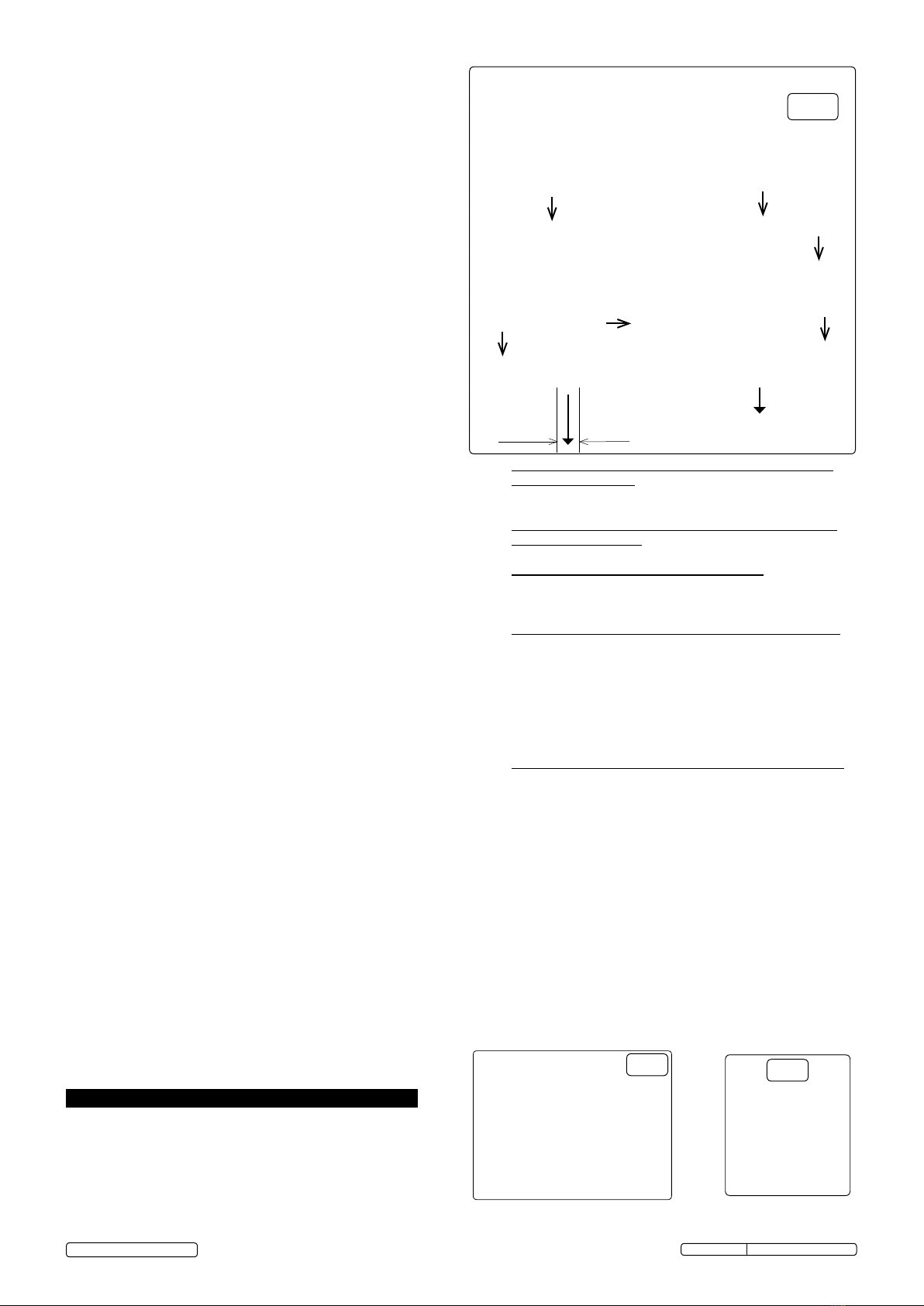
fig.3
In order to keep the compressor in good working condition,
periodic maintenance is essential.
WARNING! Before performing any maintenance
operation, switch off the compressor, disconnect from
electricity supply and release all air from the tank.
IMPORTANT! Failure to carry out maintenance tasks may
invalidate the warranty on your compressor.
fig.4 fig.5
SAC9030VE Issue No: 1 - 18/06/13
Original Language Version
©Jack Sealey Limited 2013
1/4 BSP
Male parallel
1
2
39 (off)
6
5
7
4 (off)
Regulated
supply
Unregulated
supply (tank
pressure)
Pull up (on)
Push down (off)
8
Internal