twin busch TW M-02 Owner's manual

TWIN BUSCH GmbH
Technical changes for purposes of a technical advancement as well as deviation in colour, errors and printing mistakes are reserved.
- 1 -

TWIN BUSCH GmbH
Technical changes for purposes of a technical advancement as well as deviation in colour, errors and printing mistakes are reserved.
- 2 -

TWIN BUSCH GmbH
Technical changes for purposes of a technical advancement as well as deviation in colour, errors and printing mistakes are reserved.
- 3 -
SCISSOR LIFT INSTRUCTION MANUAL
INDEX PAGE
1. Packing, transport and storage......................................................................................................................- 4 -
1.1 Packing:................................................................................................................................................- 4 -
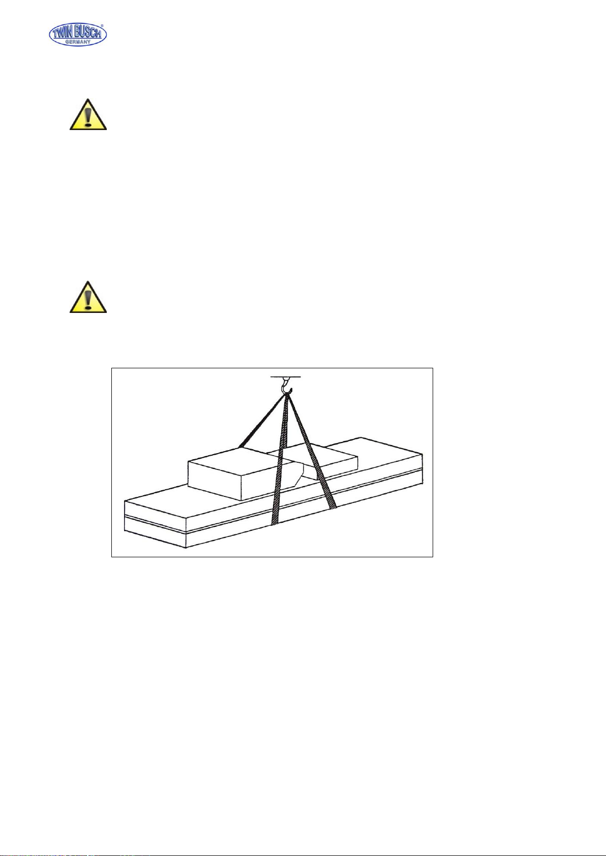
1.2 Transport:..............................................................................................................................................- 5 -
1.3 Storage:.................................................................................................................................................- 5 -
2. Manual introduction........................................................................................................................................- 6 -
3. Description of the machine.............................................................................................................................- 6 -
3.1 Machine Application..............................................................................................................................- 6 -
3.2 Structure Features.................................................................................................................................- 6 -
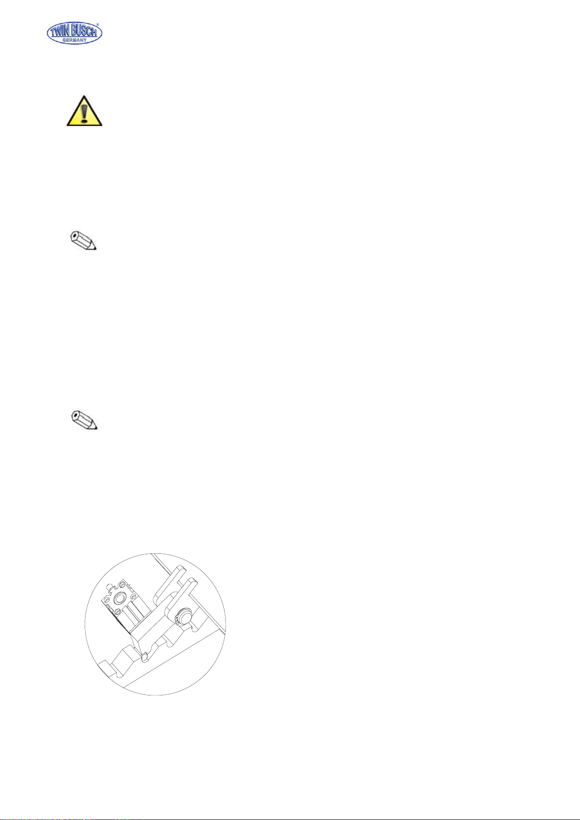
3.3 Safety lock structure..............................................................................................................................- 6 -
3.4 Equipment.............................................................................................................................................- 7 -
3.5 Frame....................................................................................................................................................- 7 -
3.6 Power unit.............................................................................................................................................- 7 -
4. Specifications.................................................................................................................................................- 8 -
4.1 Main technical parameter......................................................................................................................- 8 -
4.2 External dimension drawing..................................................................................................................- 9 -
5 Operation.....................................................................................................................................................- 10 -
6 Maintenance and care.................................................................................................................................. - 11 -
7 Circuit diagram............................................................................................................................................. - 11 -
8 Gas loop diagram......................................................................................................................................... - 11 -
9 Explosion drawing ....................................................................................................................................... - 11 -
10 Accessory packing list................................................................................................................................. - 11 -

TWIN BUSCH GmbH
Technical changes for purposes of a technical advancement as well as deviation in colour, errors and printing mistakes are reserved.
- 4 -
1. Packing, transport and storage
All packing, lifting, handling, transport and unpacking operations are to be performed exclusively
by expert personnel.
1.1 Packing:
Packing List
3M:1920*680*220 5M:2490*755*240
Picture 1(Packing dimension picture)
NO.
Name
Accessory name and quantity
1
Frame
Frame 1 piece
2
Accessory box
Tyre clamp spare part 1 piece
Table 1

TWIN BUSCH GmbH
Technical changes for purposes of a technical advancement as well as deviation in colour, errors and printing mistakes are reserved.
- 5 -
1.2 Transport:
Packing can be lifted or moved by lift trucks, cranes or bridge cranes. In case of slinging, a
second person must always take care of the load, in order to avoid dangerous oscillations.
During loading and unloading operation, goods must be handled by vehicles or ships.
At the arrival of the goods, verify that all items specified in the delivery notes are included. In case of
missing parts possible defects or damage may due to transport operations.
If finding missing parts, possible defects or damage due to transport, one should examine damaged
cartons according to <<Accessories Packing List.>> to verify the condition of damaged goods and
missing parts, also the person in charge or the carrier must be immediately informed.
The machine is heavy goods! Don’t take manpower load and unload and transporting way into
consideration, the safety of working is important.
Furthermore, during loading and unloading operation goods must be handled as shown in the
picture. (Picture 2)
Picture 2 (Goods-lifted)
1.3 Storage:
-The machine equipment should be stocked in the warehouse, if stocked outside should do the disposal
well of waterproof.
-Use box truck in the process of transport, use container storage when shipping.
-The control box should be placed perpendicularly during the transport; and prevent other goods from
extrusion.
-The temperature for machine storage : -25ºC-- 55ºC

TWIN BUSCH GmbH
Technical changes for purposes of a technical advancement as well as deviation in colour, errors and printing mistakes are reserved.
- 6 -
2. Manual introduction
This manual has been prepared for workshop personnel expert in the use of the lift operator and
technicians responsible for routine maintenance fitter.
Workers should read the <<Instruction & Maintenance Manual>> carefully before carrying out any
operation with the lift. This manual contains important information regarding:
-The personal safety of operators and maintenance workers.
-Lift safety.
-The safety of lifted vehicles.
Several tips should be done by the operator as follow:
1.Well conserving the manual. Manufacturer owns the right to make little change for the manual owing to
the improvement of technology.
2.Good disposal the used oil.
3.The machine must be demolished by authorized technicians, just like for assembling
3. Description of the machine
3.1 Machine Application
Electric hydraulic motorcycle lift can lift all kinds of vehicle whose weight is less than 300kg/500kg,
It can be used in motorcycle service shop for tyre service and vehicle maintenance.
3.2 Structure Features
-Convenient and portable structure, for tyre and wheelbase maintenance.
-Lifting height 1200mm, suitable for all kinds of motorcycle
-Double safety devices, hydraulic locking and mechanical safety clamp, ensure its stability during landing
-Two pedal switches to control the pneumatic front tyre clamp.
3.3 Safety lock structure
Picture 3

TWIN BUSCH GmbH
Technical changes for purposes of a technical advancement as well as deviation in colour, errors and printing mistakes are reserved.
- 7 -
3.4 Equipment
-Machine basement (The position and space of equipment installation)
-Machine frame (The main structure of lift and insurance institution)
-Power unit (Machine-controlled part)
3.5 Frame
Make of base plate, platform and hydraulic cylinder.
3.6 Power unit
It is made up of hydraulic pump, motor, oil hose and electric control box
Function of each valve on the power unit
Name
Function
Gear pump
Extract hydraulic oil and provide high pressure.
Valve block
Connect the motor and the gear pump.
Motor
Provide power for the gear pump.
Overflow valve
Adjust oil pressure.
Throttle valve
Adjust the speed of falling.
Lowering solenoid valve
Control flow of the hydraulic oil.
One-way valve
Control the one-way flow of hydraulic oil.
Picture 4
Platform Wheel
clamping device
Loading dock
board Oli cylinder
Power unit
Connecting rod
Base plate

TWIN BUSCH GmbH
Technical changes for purposes of a technical advancement as well as deviation in colour, errors and printing mistakes are reserved.
- 8 -
4. Specifications
4.1 Main technical parameter
Machine type
3M
5M
Drive
Power unit
Lifting capacity
300kg
500kg
Machine lift height
1200mm
Platform initial height
180mm
200mm
Platform length
1800mm
2480mm
Platform width
570mm
720mm
Lifting time
≤20s
≤30s
Descent time
≤20s
≤30s
Whole machine length
2360mm
3170mm
Whole machine width
670mm
820mm
Power supply
2/PE~220V, 50Hz,10A
Whole machine power
0.75kw
Hydraulic oil
1.5L corresponds to wearable hydraulic oil
Gas pressure
Working temperature
5-40℃
Working humidity
30-95%
Noisy
< 70db
Installation height
height above sea level≤1000M
Storage temperature
-25℃~55℃
Table 2

TWIN BUSCH GmbH
Technical changes for purposes of a technical advancement as well as deviation in colour, errors and printing mistakes are reserved.
- 9 -
4.2 External dimension drawing
Picture 5 (Lift dimension picture)
1200
460/545
450/560
200/250
1800/2480
2310/3170
180/200
570/720
670/820

TWIN BUSCH GmbH
Technical changes for purposes of a technical advancement as well as deviation in colour, errors and printing mistakes are reserved.
- 10 -
5. Operation
There are two pedal switches (one for UP and the other for DOWN) at both the left and right side of the machine’s
base (picture 6), and one pedal switch at the left side (picture 7) to control the pneumatic front tyre clamp.
When lifting up to the top, the machine will cut off the power supply automatically (picture 8).When falling, step the
DOWN pedal switch to unlock for falling.
There is a throttle valve at the opposite of the oil hose. User can use it to control the falling speed. There is a door at
the end of the platform. Pull the door back to let it down (picture 9).When the front tyre is clamped, pay attention to
the position of the disc (picture 10). Before removing the machine, use a spanner to draw back the mobile wheels
for movement (picture 11)
Caution: The machine can be used only when the four mobile wheels are put away and the base
touches the flat and hard ground completely
Picture 6
Picture 7
Picture 8
Picture 9
Picture 10
Picture 11

TWIN BUSCH GmbH
Technical changes for purposes of a technical advancement as well as deviation in colour, errors and printing mistakes are reserved.
- 11 -
6. Maintenance and care
Skilled personnel only is allowed to perform the operations
Daily checking items
The user must perform daily check. Daily check of safety system is very important –the discovery of device failure
before action could save your time and prevent you from great loss, injury or casualty.
·Always wipe clean, keep the machine clean.
·Clear barriers and ground oil, keep the working condition clean.
·Check the integrity of each safety devices, ensure the motion is flexible and reliable.
·Check the reliability of limit switch motion.
·Check whether oil leakage of the machine exist.
Weekly checking items
·All bearings and hinges on this machine must be lubricated once a week by using an oiler
·Check the working conditions of safety parts.
·Check the amount of oil left in the oil tank. Oil is enough if the carriage can be raised to highest position. Otherwise,
oil is insufficient.
Monthly checking items
·The safety gear and other movable parts must be lubricated one month.
·Check the abrasion and leakage of oil hose.
Yearly checking items
·The hydraulic oil must be replaced one time each year. The oil level should always be kept at upper limit position.
·.Check abrasion and damage of all the active parts.
·.Check the lubrication of roller. Lubricate it if drag phenomenon exist.
-The machine should be lower to the lowest position when replace hydraulic oil, then let the old oil out,
and should be filtering the hydraulic oil.
-Each team checks the agility and reliability of pneumatic safety equipment.
Storage after use
When the machine does not use for a long time:
·.Cut off the power supply and lubricate all the active parts.
·.Drain the hydraulic oil of oil cylinder, oil hose and oil tank.
·Sheathe the machine with dust-proof cover.

TWIN BUSCH GmbH
Technical changes for purposes of a technical advancement as well as deviation in colour, errors and printing mistakes are reserved.
- 12 -
7. Circuit diagram

TWIN BUSCH GmbH
Technical changes for purposes of a technical advancement as well as deviation in colour, errors and printing mistakes are reserved.
- 13 -
D35-1003
H-030-050011-1
AC contactor
D35-1004
fuse
8. Gas loop diagram
3M
5M
D35-1003
D35-1004

TWIN BUSCH GmbH
Technical changes for purposes of a technical advancement as well as deviation in colour, errors and printing mistakes are reserved.
- 14 -
9. Explosion drawing
M01-100
Complete platform assembly
M02-100
Complete platform assembly
M01-200
Complete connecting rod assembly
M02-200
Complete connecting rod assembly
M01-300
Complete oil cylinder assembly
M02-300
Complete oil cylinder assembly
M01-400
Complete base seat assembly
M02-400
Complete base seat assembly
M01/M02-500
Complete power unit assembly
M02-100
M02-200
M02-300
M02-400
M01-100
M01-200
M01-300
M01-400
M01 M02
M01-500 M01-500

TWIN BUSCH GmbH
Technical changes for purposes of a technical advancement as well as deviation in colour, errors and printing mistakes are reserved.
- 15 -
FS35-311
flat washer Ø12
FS35-312
spring washer Ø12
M01-101
hex bolt M12X25
M01-102
clamp assembly
M01-103
pressing plate
D35-405
nut M16
M01-100
FS35-311
FS35-312
M01-101
M01-102
M01-103 D35-405
M01-104
M01-105
M01-106
M01-107
M01-108
M01-109
M01-110
M01-111
M01-112
FS35-310
M01-113
M02-100
FS35-311
FS35-312
M01-101
M02-101
M02-102
D35-405
M01-105
M01-106
M01-107
M02-103
M02-104
M01-110
M02-106
M01-112
FS35-310
M01-113
M02-105

TWIN BUSCH GmbH
Technical changes for purposes of a technical advancement as well as deviation in colour, errors and printing mistakes are reserved.
- 16 -
M01-104
Guide rod
M01-105
hex socket head cap screw M8X25
M01-106
spring washer Ø8
M01-107
flat washer Ø8
M01-108
clamping cylinder SC50X125
M01-109
platform
M01-110
spring
M01-111
guide tube
FS35-310
shaft snap ring Ø10
M01-112
roller
M01-113
straight pin
M02-101
clamp assembly
M02-102
pressing plate
M02-103
air cylinder
M02-104
Guide rod
M02-105
platform
M02-106
guide tube
M01-200
M02-200 M01-201
M02-201
FS35-227
M01-202
M02-202
M01-203
M02-203 M01-204
M02-204
M01-205
M02-205
M01-206
M02-206
D35-104
M01-208
H30-106
M01-211
M02-208
M01-212
FS35-324
D35-516
M01-207
D35-104 FS35-227
FS35-227
M01-209
M01-210
M02-207
M01-213
M01-214
D35-116

TWIN BUSCH GmbH
Technical changes for purposes of a technical advancement as well as deviation in colour, errors and printing mistakes are reserved.
- 17 -
M01-201
top plate pin
M02-201
top plate pin
FS35-227
shaft snap ring Ø20
M01-202
Inner connecting rod
M02-202
Inner connecting rod
M01-203
Outer connecting rod
M02-203
Outer connecting rod
M01-204
base pin
M02-204
base pin
D35-104
shaft snap ring Ø25
M01-205
connecting rod pin
M02-205
connecting rod pin
M01-206
Stationary shaft of oil cylinder
M02-206
Stationary shaft of oil cylinder
M01-207
insurance claw shaft
M01-208
roller
M01-209
bolt
M01-210
loading dock board support
M02-207
loading dock board support
H30-106
hex nut M12
M01-211
loading dock board
M02-208
loading dock board
FS35-324
shaft snap ring Ø12
M01-212
loading dock board roller
M01-213
hex bolt M12X35
M01-214
hex socket head cap screw M6X25
D35-516
cylinder SSDA25X25

TWIN BUSCH GmbH
Technical changes for purposes of a technical advancement as well as deviation in colour, errors and printing mistakes are reserved.
- 18 -
M01-400
base complete
M01-401
Foot valve
D35-515
flat washer Ø6
D35-514
spring washer Ø6
M01-402
hex socket head cap screw M6X35
M01-403
Gas pedal
D35-522
hex bolt M8X16
M01-404
Electric control box
D35-521
limit switch LZ7312
H30-105
hex bolt M12X50
M01-405
hex bolt M8X20
M01-106
spring washer Ø8
M01-107
flat washer Ø8
M01-406
base
M02-401
base
M01-407
pedal switch
M01-408
cross sunk head tapping screw
M01-400
M02-400
M01-401
D35-315
D35-514
M01-402
M01-403
D35-522
M01-404
D35-521
H30-105
M01-405
M01-106
M01-107
M01-406
M02-401
M01-407
M01-408
D35-409
M01-409
M01-410
M01-411
M01-412
M01-413

TWIN BUSCH GmbH
Technical changes for purposes of a technical advancement as well as deviation in colour, errors and printing mistakes are reserved.
- 19 -
D35-409
hex nut M8
M01-409
caster
M01-410
hex bolt M8X65
M01-411
bend connector
M01-412
quick connector(female)
M01-413
quick connector(male)
M01-300
M01-301
M01-302
M01-303
M01-304
M01-305
M01-306
M01-307
M01-308
M01-301
M02-301
M02-302
M02-303
M02-304
M02-305
M02-306
M02-307
M02-300

TWIN BUSCH GmbH
Technical changes for purposes of a technical advancement as well as deviation in colour, errors and printing mistakes are reserved.
- 20 -
M01-301
dust-proof ring Ø32X40X5.3
M01-302
Wear ring
M01-303
oil cylinder cover
M01-304
O-ring Ø45X3.55
M01-305
piston rod
M01-306
combined seal ring Ø45X29X18.4
M01-307
piston(
M01-308
oil cylinder
M01-501
1 phase motor(M01,M02)
M01-502
3 phase motor(M01,M02)
M01-503
Annectent spinde (M01,M02)
M01-504
Overflow valve(M01,M02)
M01-505
Throttle valve(M01,M02)
M01-506
Escape oil hose(M01,M02)
M01-507
Gear pump(M01,M02)
M01-508
Suction oil hose(M01,M02)
M01-509
Oil tank(1.5L) (M01,M02)
M01-510
Valve seat(M01,M02)
M01-301
dust-proof ring Ø32X40X5.3
M02-301
Wear ring
M02-302
oil cylinder cover
M02-303
O-ring Ø45X3.55
M02-304
piston rod
M02-305
combined seal ring Ø45X29X18.4
M02-306
piston
M02-307
oil cylinder
M01/M02-500
M01-509 M01-508
M01-507
M01-506
M01-505
M01-504 M01-503
M01-501/M01-502
M01-511
D35-904
D35-903
M01-510
Table of contents
Other twin busch Lifting System manuals
Popular Lifting System manuals by other brands

GYS
GYS ERGO LIFT 1000 ROLL Operation and maintenance manual

Powermate
Powermate LiftGate LV-TL Series Installation & operation manual

Sav
Sav SAV 531.42 operating instructions

Maxon
Maxon GPC 22 X1 installation manual

Snorkel
Snorkel S2255RTE Repair parts manual

AUTEC
AUTEC ALM-6040FL User & installation manual

Grundfos
Grundfos Sololift2 C-3 Installation and operating instructions

Savaria
Savaria Ceiling Lift Track Bridge owner's manual

OMCN
OMCN 112/A Instructions for use and maintenance / spare parts

Snorkel
Snorkel SL20 Operator's manual

Dhollandia
Dhollandia DH-LSP.07 installation manual

Motorline professional
Motorline professional CHAINLIFT User& installer's manual