manuals.online logo
Brands
  1. Home
  2. •
  3. Brands
  4. •
  5. Sealey
  6. •
  7. Measuring Instrument
  8. •
  9. Sealey TA300 User manual

Sealey TA300 User manual

Features 3-1/2 digit, 10mm LCD display, data hold, auto ranging, over-range protection and indication, auto-power-off and spotlight.
Measures AC and DC voltages, resistance, capacitance, frequency and duty cycle and has diode and continuity test functions.
Supplied with crocodile clip, cigarette lighter plug, two probes, probe guard and 1.3m cable.
1.1. PERSONAL PRECAUTIONS
!When using this meter, please observe all normal safety rules concerning:
Protection against the dangers of electric current.
Protection of the meter against misuse.
"DO NOT use leads if damaged or if the wire is exposed in any way.
1.2. GENERAL SAFETY INSTRUCTIONS
!Familiarise yourself with the application and limitations of the meter as well as the potential hazards. IF IN ANY DOUBT CONSULT
A QUALIFIED ELECTRICIAN.
!Before use, verify the meter’s operation my measuring a known voltage.
!Before changing functions, disconnect test leads from the circuit under test.
!Connect the test lead before connecting the test probe. When disconnecting, remove the test probe first.
#WARNING! Disconnect circuit power and discharge all high-voltage capacitors before testing resistance, diode or continuity.
!Use proper function and range for the measurement.
!Before operating the “Select” switch, disconnect the leads and test probes from the circuit under test.
#WARNING! Never perform resistance measurements on live circuits.
!Always be careful when working with voltages above 60Vdc or 30Vac rms. Keep your fingers behind the probe barriers while
measuring.
#WARNING! CATll-Measurement. Category ll is for measurements performed on circuits directly connected to low-voltage
supply. (Examples are measurements on domestic appliances, portable tools etc.). DO NOT use the meter to measure within
Measurement Categories lll and lV.
"DO NOT use the meter around explosive gas, vapour or dust.
!Remove the test lead and probe from a circuit before opening the battery compartment.
"DO NOT operate the meter with the battery cover removed.
!When not in use, store the meter carefully in a safe, dry, childproof location. Storage temperature range - 10OC to 50OC.
#WARNING! The warnings, cautions and instructions discussed in this manual cannot cover all possible conditions and situations
that may occur. It must be understood that common sense and caution are factors which cannot be built into this product, but must
be applied by the operator.
INSTRUCTIONS FOR:
AUTOMOTIVE PEN PROBE DIGITAL METER
MODEL: TA300
Thank you for purchasing a Sealey product. Manufactured to a high standard this product will, if used according to these instructions and properly maintained,
give you years of trouble free performance.
1. SAFETY INSTRUCTIONS
IMPORTANT: PLEASE READ THESE INSTRUCTIONS CAREFULLY. NOTE THE SAFE OPERATIONAL REQUIREMENTS, WARNINGS & CAUTIONS. USE THE PRODUCT
CORRECTLY AND WITH CARE FOR THE PURPOSE FOR WHICH IT IS INTENDED. FAILURE TO DO SO MAY CAUSE DAMAGE AND/OR PERSONAL INJURY AND WILL
INVALIDATE THE WARRANTY. PLEASE KEEP THESE INSTRUCTIONS SAFE FOR FUTURE USE.
2. FEATURES
.Autorange.
.Overrange protection for all ranges.
.The maximum, permitted voltage between any terminal and ground: 600Vdc/ac rms.
.Display: . . . . . . . . . . . . . . . . .LCD.
. Polarity indication: . . . . . . . . .”-” for negative polarity.
.Overrange indication: . . . . . . .“OL” or “-OL”.
.Sampling time: . . . . . . . . . . .0.4 second.
.Auto-power-off: . . . . . . . . . . .15 minutes without operation.
.Power supply: . . . . . . . . . . . .1.5V X 2 AAA.
.Low battery indication: . . . . . .” ” on display.
. Operating temperature: . . . . . .0°C - 40°C.
.Storage temperature: . . . . . . .-10°C - 50°C.
TA300 - 1 - 310807
Item Description (Fig.1)
1. “HOLD” button.
After “Hold” button is pressed, the present reading will be held in the display.
2. “LIGHT” button.
To enable spotlight function, press “Light” button.
To disable, press the “Light” button again.
3. “SELECT” button.
When meter is in the Vdc range press the “Select” button to change to
the Vac range, press “Select” again and the meter will return to the Vdc range..
When the meter is in the resistance range press the “Select” button to change to
to diode range. Press “Select” again, for continuity range. Press “Select”
again for capacitance range.
When the meter is in frequency range, press the “Select” button for
duty cycle.
4. “POWER” button.
The “Power” button is used for switching the meter on.
Press “Power” again to turn the meter off.
5. “FUNCTION” switch.
Use “Function” switch to select between Vac, Vdc, resistance,
capacitance, frequency, duty cycle, continuity test, audible continuity
and diode test.
6. Test probe. (+Test Probe)
7. Test lead. (-Test Lead)
8. Crocodile clip.
9. Cigarette lighter adaptor.
1
2
3
5
6
4
7
8
9
DC VOLTAGE
Range Resolution Accuracy
400mV 0.1mV
4V 1mV ± (0.8%+4)
40V 10mV
400V 100mV
600V 1V ± (1%+4)
RESISTANCE
Range Resolution Accuracy
400Ω0.1Ω± (1.2%+2)
4kΩ1Ω
40kΩ10Ω± (1%+2)
400kΩ100Ω
4MΩ1kΩ± (1.2%+2)
40MΩ10kΩ± (1.5%+2)
CAPACITANCE
Range Resolution Accuracy
4nF 1pF ± (25%+5)
40nF 10pF
400nF 100pF
4µF 1nF ± (10%+5)
40µF 1nF
100µF 100nF
DUTY CYCLE
Range Resolution Accuracy
0.1% - 99% 0.01% ± (2.5%+4)
DIODE
Range Resolution
Open-circuit Voltage:
1mV About 1.5V.
Forward voltage:
About 0.5 - 0.8V
FREQUENCY
Range Accuracy
9.999Hz
99.99Hz
999.9Hz ± (1.5%+4)
9.999kHz
99.99kHz
999.9kHz
10MHz
AC VOLTAGE
Range Resolution Accuracy
4V 1mV
40V 10mV ± (0.8%+6)
400V 100mV
600V 1V ± (1.2%+6)
CONTINUITY
If < 50Ω, the buzzer will sound
Accuracy is specified for a period of one year after calibration and at 23 ± 5°C with relative humidity up to 75%.
Accuracy specifications take the form of:
± (% of Reading + number of least significant digits).
Input impedance: 10Ω
Overload protection: 250Vdc or rms ac
Input voltage range: 0.5 - 50 Vp-p
Note: When the resistance is between 50Ω and
120Ω, the buzzer may or may not sound. When
the resistance is more than 120Ω, the buzzer
will not sound.
Input voltage range: 0.5 - 50 Vp-p
Overload protection: 250Vdc or rms ac
Input impedance: 10MΩ
Frequency response: 40 - 400\Hz
3. SPECIFICATION
TA300 - 1 - 310807
Fig.1
4. OPERATION
4.1. MEASURE VOLTAGE
4.1.1. Set the function switch in V /A~ position, press “SELECT” button to select Vdc or Vac measuring mode.
4.1.2. Connect the test lead and test probe across the source or circuit to be measured.
4.1.3. Read the reading.
NOTE! The max. permitted voltage is 600Vac/dc rms.
The meter may show an unsteady reading when the test lead and test probe are not in contact with the circuit to be
measured, this is normal because the meter’s sensitivity is very high. When the test lead and test probe touch the circuit to be
measured, the display will show the true reading.
4.2. MEASURING RESISTANCE
4.2.1. Set the function switch in the “ Ω“ position.
4.2.2. Connect the test lead and test probe across the circuit to be measured.
4.2.3. Read the reading.
NOTE! When the measured resistance is more than 1MΩ, it will take several seconds for the reading to be steady.
When the test lead and test probe are open, the display will show “OL” for overload indication.
Before you measure in-circuit resistance, ensure that the power supply has been switch off and all the capacitors have
been fully discharged.
4.3 TESTING DIODE
4.3.1. Set the function switch in “ ” position.
4.3.2. Press the “SELECT” button to set the meter in diode range.
4.3.3. Connect the test probe to the anode of the diode and the black test lead to the cathode of the diode.
4.3.4. Read the reading.
NOTE! The display will show the approximate value of the forward-voltage drop of the diode. If you connect the test probe and
test lead across the diode in the wrong direction, the display will show "OL".
4.4. TESTING FOR CONTINUITY
4.4.1. Set the function switch in " " position.
4.4.2. Press the "SELECT" button to set the meter in " " range.
4.4.3. Connect the test probe and test lead across the circuit to be measured.
4.4.4. If < about 50Ω, the buzzer will sound.
4.4.5. Read the reading.
4.5. MEASURING CAPACITANCE
4.5.1. Set the function switch in " " position.
4.5.2. Press the "SELECT" button to set the meter in capacitance range.
4.5.3. Connect the test probe and test lead across the capacitor to be measured.
4.5.4. Read the reading.
NOTE! When you measure a high-voltage capacitor, it will take several seconds for reading to steady (30 seconds for
100mF range).
4.6. MEASURING DUTY CYCLE
4.6.1. Set the function switch in "DUTY" position.
4.6.2. Press the "SELECT" button to set the meter in duty cycle range.
4.6.3. Connect the test probe and test lead across the source or load to be measured.
4.6.4. Read the reading.
4.7. MEASURING FREQUENCY
4.7.1. Set the function switch in "Hz" position.
4.7.2. Press the "SELECT" button to set the meter in Hz range.
4.7.3. Connect the test probe and test lead to the signal to be measured.
4.7.4. Read the reading.
4.8. AUTO POWER-OFF
4.8.1. When idle, the meter will automatically power off and give 5 short beeps and one long beep. If you move the function switch
or press “HOLD” or “SELECT”, the meter will turn on.
TA300 - 1 - 310807
For Jack Sealey Ltd. Sole UK importer of Sealey Professional Tools.
Declaration of Conformity We, the sole UK importer, declare that the product listed below is in conformity with the
following standards and directives.
The construction file for this product is held by the Manufacturer
and may be inspected, by a national authority, upon request to
Jack Sealey Ltd.
AUTOMOTIVE PEN PROBE
DIGITAL METER
MODEL: TA300
2006/95/EC Low Voltage Directive
2004/108/EC EMC Directive
93/68/EEC CE Marking Directive
2002/95/EC RoHS Directive
2002/96/EC WEEE Directive
Signed by Tim Thompson 31st August 2007
Environmental Protection.
Recycle unwanted materials instead of disposing of them as waste. All tools, accessories and packaging should
be sorted, taken to a recycle centre and disposed of in a manner which is compatible with the environment.
When product is no longer required, it must be disposed of in an environmentally protective way.
Do not incinerate battery as it may explode when exposed to fire.
Do not attempt to open battery.
TA300 - 1 - 310807
5. MAINTENANCE
5.1. BATTERY REPLACEMENT
5.1.1 To replace the batteries, remove the screw from the battery compartment cover, replace the old batteries with new
batteries of the same type, replace the cover and reinstall the screw.
NOTE: Pay attention to the polarity of the new batteries, do not reverse them, otherwise the unit will be damaged.
Only use the specified batteries: 2 x 1.5V AAA.
#WARNING! DO NOT attempt to repair or service your meter unless you are qualified to do so and have the relevant
calibration, performance test, and service information. To avoid electrical shock or damage to the meter do not get water
inside the case.
5.2. Periodically wipe the case with a damp cloth and mild detergent. Do not use solvents.
5.3. Turn the meter off when not in use and remove the batteries if stored for a long period of time.
5.7. Do not store the meter in a place of high humidity or high temperature.
01284 757500
01284 703534 [email protected]
Sole UK Distributor
Sealey Group,
Bury St. Edmunds, Suffolk.
www.sealey.co.uk
Web
email
Available Parts.
Item Part No. Description
1. TA300.01 Lighter Clip
2. TA300.02 Probe
3. TA300.03 Crocodile Clip
1
2
3
NOTE: It is our policy to continually improve products and as such we reserve the right to alter data, specifications and component parts without prior notice.
IMPORTANT: No liability is accepted for incorrect use of this equipment. WARRANTY: Guarantee is 12 months from purchase date, proof of which will be
required for any claim. INFORMATION: For a copy of our latest catalogue and promotions call us on 01284 757525 and leave your full name and
address, including postcode.

Other Sealey Measuring Instrument manuals

Sealey AK9629E User manual

Sealey

Sealey AK9629E User manual

Sealey AK4013 User manual

Sealey

Sealey AK4013 User manual

Sealey TP91300.V2 User manual

Sealey

Sealey TP91300.V2 User manual

Sealey VSE5863 User manual

Sealey

Sealey VSE5863 User manual

Sealey VS8196 User manual

Sealey

Sealey VS8196 User manual

Sealey PP5 User manual

Sealey

Sealey PP5 User manual

Sealey SA9302 User manual

Sealey

Sealey SA9302 User manual

Sealey TA091 User manual

Sealey

Sealey TA091 User manual

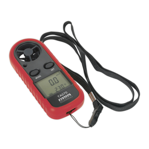
Sealey TA070 User manual

Sealey

Sealey TA070 User manual

Sealey VS0567 User manual

Sealey

Sealey VS0567 User manual

Sealey AK9638D User manual

Sealey

Sealey AK9638D User manual

Sealey AK9991 User manual

Sealey

Sealey AK9991 User manual

Sealey TP101 User manual

Sealey

Sealey TP101 User manual

Sealey 6-24V AUTO PROBE PLUS User manual

Sealey

Sealey 6-24V AUTO PROBE PLUS User manual

Sealey MM302.V2 User manual

Sealey

Sealey MM302.V2 User manual

Sealey VS0563 User manual

Sealey

Sealey VS0563 User manual

Sealey TA200 User manual

Sealey

Sealey TA200 User manual

Sealey PPLK User manual

Sealey

Sealey PPLK User manual

Sealey MM404.261 User manual

Sealey

Sealey MM404.261 User manual

Sealey GA45 User manual

Sealey

Sealey GA45 User manual

Sealey TA201 User manual

Sealey

Sealey TA201 User manual

Sealey Auto Service Series User manual

Sealey

Sealey Auto Service Series User manual

Sealey TA050 User manual

Sealey

Sealey TA050 User manual

Sealey TA303 User manual

Sealey

Sealey TA303 User manual

Popular Measuring Instrument manuals by other brands

Rinstrum 400 Series Operator's manual

Rinstrum

Rinstrum 400 Series Operator's manual

APS 3A Series Operation manual

APS

APS 3A Series Operation manual

ROOTECH Accura 2350-GW user guide

ROOTECH

ROOTECH Accura 2350-GW user guide

Ceyear 4957D quick start guide

Ceyear

Ceyear 4957D quick start guide

getemed PhysioMem PM 100 2G operating manual

getemed

getemed PhysioMem PM 100 2G operating manual

jenway Genova Nano operating manual

jenway

jenway Genova Nano operating manual

Lovato DME D120 T1 instruction manual

Lovato

Lovato DME D120 T1 instruction manual

Pessl METOS CLIMA LoRa user manual

Pessl

Pessl METOS CLIMA LoRa user manual

Maeraj PHV-20 Instruction manual and safety instructions

Maeraj

Maeraj PHV-20 Instruction manual and safety instructions

Fluke RUSKA 2456-LEM user manual

Fluke

Fluke RUSKA 2456-LEM user manual

YOKOGAWA WT500 user manual

YOKOGAWA

YOKOGAWA WT500 user manual

CDI Meters CDI 5100 Installation and operating instructions

CDI Meters

CDI Meters CDI 5100 Installation and operating instructions

G.R.A.S. Type 40HT instruction manual

G.R.A.S.

G.R.A.S. Type 40HT instruction manual

Saluki STB8827 Series Operation manual

Saluki

Saluki STB8827 Series Operation manual

Siemens Sitrans F Series operating instructions

Siemens

Siemens Sitrans F Series operating instructions

AEMC instruments Clamp-On 3705 user manual

AEMC instruments

AEMC instruments Clamp-On 3705 user manual

Dakota Digital VHX-66C-NOV manual

Dakota Digital

Dakota Digital VHX-66C-NOV manual

Spectra Precision LL100N user guide

Spectra Precision

Spectra Precision LL100N user guide

manuals.online logo
manuals.online logoBrands
  • About & Mission
  • Contact us
  • Privacy Policy
  • Terms and Conditions

Copyright 2025 Manuals.Online. All Rights Reserved.