5. ASSEMBLY
5.1. BOTTOM PANEL ASSEMBLY
5.1.1. Secure the metal feet (fig 2 - 8) to the bottom panel (fig 2 - 7) with M6 x 12 cross head screws (fig 2 - 3).
5.1.2. Locate and thread the adjustable feet (fig 2 - 9) into the bottom panel.
5.2. PANEL ASSEMBLY
5.2.1. Prior to panel assembly lay a soft mat or similar on the floor to protect the paint finish
5.2.2. Attach right side panel (fig 3 - 4) to back panel (fig 3 - 2) by sliding it’s edge into the groove on the side edge of the back panel.
5.2.3. Repeat for left side panel (fig 3 - 15).
5.3. BOTTOM PANEL AND SIDES ASSEMBLY
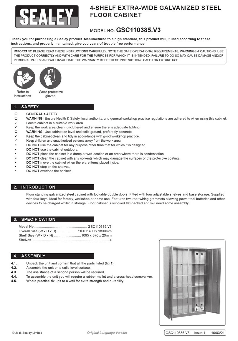
5.3.1. Locate and align bottom panel assembly fixing holes with the fixing holes in the side and bottom panel assembly (fig 4).
5.3.2. Secure with M6 x 12 cross head screws (fig 4 - 3).
5.4. TOP PANEL TO SIDES ASSEMBLY
5.4.1. Locate and align top panel (fig 5 - 1) with fixing holes in the side panels and secure with M6 x 12 cross head screws (fig 5 - 3).
5.4.2. Secure top panel (fig 5 - 1) to front fixing holes on side panels with M6 x 12 cross head screws (fig 5 - 3).
5.5. FINAL PANEL FIXINGS
5.5.1. With the assistance of another person rotate the cabinet assembly onto it’s side (fig 6).
5.5.2. Secure the remaining fixings of the bottom panel assembly and top panel with M6 x 12 cross head screws (fig 6 - 3).
5.6. ATTACHING THE SHELVES
5.6.1. With the assistance of another person stand the cabinet upright (fig 7).
5.6.2. Insert the shelf supports (fig 7 - 6) into the slots on the back panel and
inner face of the front panel, at the desired heights.
5.6.3. Fit the shelf (fig 7 - 5) onto the appropriate set of shelf supports.
5.6.4.
Press the shelf firmly until locked onto the shelf supports.
5.6.5. The shelves can be adjusted by removing them offthe supports and
repositioning the supports at the new desired height.
5.7. ATTACHING THE DOOR
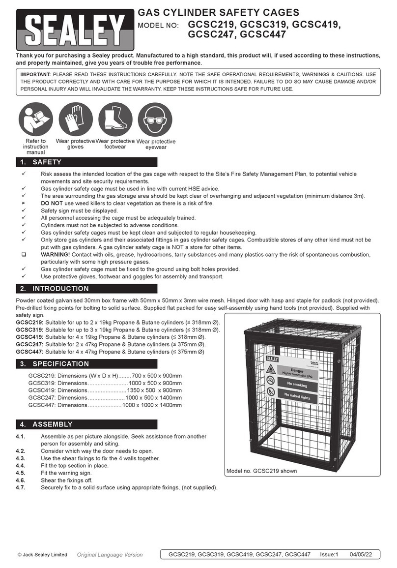
NOTE: The door (fig 8 - 11) has a pin fitted at the bottom and a spring bolt fitted at the top.
5.7.1. Locate the bottom pin into the hole at the front of the base unit assembly (fig 8).
5.7.2. Pull the top spring pin down and align with the hole in the top panel rail (fig 8).
5.7.3. Release the top spring to allow the bolt to locate into the hole.
5.8. ATTACHING THE DOOR HANDLE
5.8.1. Locate the door handle (fig 9 - 14) to it’s corresponding fixing holes, on the door, and secure with M4 x 8 cross head screws
(fig 9 - 13).
APMS21 Issue 1 30/07/21
Original Language Version
© Jack Sealey Limited
fig.2 fig.3
fig.4 fig.5
fig.6
fig.7
