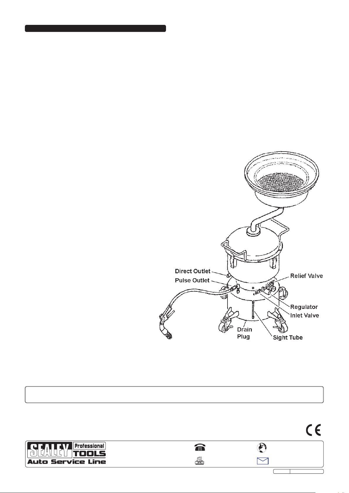
The recommended hook-up is shown below.
3.1. Ensure the air valve is in the "Off" position before connecting to the air supply.
WARNING! Ensure the air supply is clean and does not exceed pressures specified
in these Instructions. Too high an air pressure and/or unclean air will shorten
the drainer life due to excessive wear, and may be dangerous, causing
damage and/or personal injury.
3.2. Drain the compressor air tank daily and clean the air inlet filter weekly.
3.3. Line pressure should be increased to compensate for unusually long air
hoses (over 8 metres). The minimum hose diameter should be 10mm I.D.
and fittings must have the same inside dimensions.
3.4. Keep hoses away from heat, oil and sharp edges.Check hoses for
wear and make certain that all connections are secure.
INSTRUCTIONS FOR:
BRAKE DISC & LINING CLEANER 15LTR
MODEL No: VS2000
Thank you for purchasing a Sealey product. Manufactured to a high standard this product will, if used according to these instructions
and properly maintained, give you years of trouble free performance.
1. SAFETY INSTRUCTIONS
IMPORTANT: PLEASE READ THESE INSTRUCTIONS CAREFULLY. NOTE THE SAFE OPERATIONAL REQUIREMENTS, WARNINGS AND
CAUTIONS. USE THE PRODUCT CORRECTLY AND WITH CARE FOR THE PURPOSE FOR WHICH IT IS INTENDED. FAILURE TO DO SO MAY
CAUSE DAMAGE AND/OR PERSONAL INJURY AND WILL INVALIDATE THE WARRANTY. PLEASE KEEP INSTRUCTIONS SAFE FOR FUTURE USE.
2. INTRODUCTION AND ASSEMBLY
2.1. Introduction
Reduce the chances of brake dust getting airborne and help protect you and your workforce from the effects of brake dust inhalation.
Air operated brake cleaner device can be used remotely from air supply and the recycling function prolongs the life of the brake
cleaning fluid. Cranked neck makes this unit suitable for use under lift or next to ramps. Fitted with four large castor wheels, two
braked, for workshop mobility. Suitable for use with Sealey Brake Cleaning Solvent or other proprietary brands. Supplied with cleaning
brush.
2.2. Contents
2.2.1. Check the contents against the following list. If any items are damaged or missing contact your
supplier immediately.
•TankAssembly•SmallDrainPan•LargeDrainPan•DrainPanPipe•BrushandHose
•DrainPanMat
2.3. Assembly
2.3.1. Screw the small drain pan onto the threaded end of the drain pan pipe.
2.3.2. Insert other end of drain pan pipe (fig. 1.A) into the top tank fitting (fig. 1.D), as far as the spring
ring (fig. 1.B). Tighten the pipe clamp screw (fig. 1.C).
3. AIR SUPPLY
1.1. GENERAL SAFETY
WARNING! Ensure Health & Safety, local authority and general workshop practice regulations are adhered
to when using this equipment.
Familiarise yourself with the application, limitations and hazards of the cleaner.
WARNING!Disconnect the cleaner from the air supply before changing accessories, servicing or performing any maintenance.
Maintain the cleaner in good condition (use an authorised service agent).
Replace or repair damaged parts. Use genuine parts only. Unauthorised parts may be dangerous and will invalidate the warranty.
Keep the work area clean, uncluttered and ensure that there is adequate lighting.
Keep the cleaner clean for best and safest performance.
Maintain correct balance and footing. Ensure that the floor is not slippery and wear non-slip shoes.
Keep children and unauthorised persons away from the work area.
WARNING! Ensure that correct air pressure is maintained and not exceeded.
Keep air hose away from heat, oil and sharp edges. Check air hose for wear before each use and ensure that all
connections are secure.
DO NOT use the cleaner for any purpose other than that for which it is designed.
DO NOT operate the cleaner if any parts are damaged or missing as this may cause failure and/or personal injury.
DO NOT stand on the cleaner.
DO NOT adjust or tamper with the safety valve.
DO NOT move the cleaner by the hose, or yank the hose from the air supply.
DO NOT place attachments close to your face (especially eyes, ears, etc.) and do not point hose at other
persons or animals.
DO NOT allow untrained persons to operate the cleaner.
DO NOT operate the cleaner when you are tired or under the influence of alcohol, drugs or intoxicating medication.
DO NOT leave the cleaner operating unattended.
DO NOT direct air from the air hose at yourself or others.
When not in use disconnect from the air supply, vent reservoir and store in a safe, dry, childproof area.
Dispose of waste fluid in accordance with local authority regulations.
WARNING! DO NOT pollute the environment by allowing uncontrolled discharge of waste.
g.1
Original Language Version VS2000 Issue: 3 - 20/04/12