manuals.online logo
Brands
  1. Home
  2. •
  3. Brands
  4. •
  5. Sealey
  6. •
  7. Water Pump
  8. •
  9. Sealey AK453X.V3 User manual

Sealey AK453X.V3 User manual

This manual suits for next models

3

Other Sealey Water Pump manuals

Sealey AK457D User manual

Sealey

Sealey AK457D User manual

Sealey EWP40 User manual

Sealey

Sealey EWP40 User manual

Sealey WPS92A User manual

Sealey

Sealey WPS92A User manual

Sealey TP50.V3 User manual

Sealey

Sealey TP50.V3 User manual

Sealey TP97 User manual

Sealey

Sealey TP97 User manual

Sealey WPS060.V2 User manual

Sealey

Sealey WPS060.V2 User manual

Sealey BC110.V2 User manual

Sealey

Sealey BC110.V2 User manual

Sealey TP6801.V2 User manual

Sealey

Sealey TP6801.V2 User manual

Sealey WPL117A User manual

Sealey

Sealey WPL117A User manual

Sealey WPL117A User manual

Sealey

Sealey WPL117A User manual

Sealey PW12CC User manual

Sealey

Sealey PW12CC User manual

Sealey TP955.V2 User manual

Sealey

Sealey TP955.V2 User manual

Sealey wps250a User manual

Sealey

Sealey wps250a User manual

Sealey SMP60 User manual

Sealey

Sealey SMP60 User manual

Sealey TP94 User manual

Sealey

Sealey TP94 User manual

Sealey AK450DX User manual

Sealey

Sealey AK450DX User manual

Sealey TP6818 User manual

Sealey

Sealey TP6818 User manual

Sealey AK4555D User manual

Sealey

Sealey AK4555D User manual

Sealey TP6801 User manual

Sealey

Sealey TP6801 User manual

Sealey WPB050 User manual

Sealey

Sealey WPB050 User manual

Sealey WPC100A.V2 User manual

Sealey

Sealey WPC100A.V2 User manual

Sealey SWP20 User manual

Sealey

Sealey SWP20 User manual

Sealey TP6807 User manual

Sealey

Sealey TP6807 User manual

Sealey TP96.V3 User manual

Sealey

Sealey TP96.V3 User manual

Popular Water Pump manuals by other brands

Watershed Innovations HYDRAPUMP SMART FLEX Instructional manual

Watershed Innovations

Watershed Innovations HYDRAPUMP SMART FLEX Instructional manual

Graco Modu-Flo AL-5M instructions

Graco

Graco Modu-Flo AL-5M instructions

Messner MultiSystem MPF 3000 operating instructions

Messner

Messner MultiSystem MPF 3000 operating instructions

Xylem Bell & Gossett WEHT0311M Installation, operation and maintenance instructions

Xylem

Xylem Bell & Gossett WEHT0311M Installation, operation and maintenance instructions

WilTec 50739 Operation manual

WilTec

WilTec 50739 Operation manual

Franklin Electric Little Giant 555702 HRK-360S instruction sheet

Franklin Electric

Franklin Electric Little Giant 555702 HRK-360S instruction sheet

Ingersoll-Rand PD02P Series Operator's manual

Ingersoll-Rand

Ingersoll-Rand PD02P Series Operator's manual

VS ZJ Series Operating	 instruction

VS

VS ZJ Series Operating instruction

Flotec FPZS50RP owner's manual

Flotec

Flotec FPZS50RP owner's manual

SKF Lincoln FlowMaster II User and maintenance instructions

SKF

SKF Lincoln FlowMaster II User and maintenance instructions

Xylem Lowara LSB Series Installation, operation and maintenance instructions

Xylem

Xylem Lowara LSB Series Installation, operation and maintenance instructions

Water Duro Pumps DCJ500 Operating & installation instructions

Water

Water Duro Pumps DCJ500 Operating & installation instructions

Action P490 Operating instructions & parts manual

Action

Action P490 Operating instructions & parts manual

Flo King Permacore Reusable Carbon Bag Disassembly. & Cleaning Instructions

Flo King

Flo King Permacore Reusable Carbon Bag Disassembly. & Cleaning Instructions

ARO ARO PD15P-X Operator's manual

ARO

ARO ARO PD15P-X Operator's manual

Pumptec 112V Series Operating instructions and parts manual

Pumptec

Pumptec 112V Series Operating instructions and parts manual

Virax 262070 user manual

Virax

Virax 262070 user manual

Neptun NPHW 5500 operating instructions

Neptun

Neptun NPHW 5500 operating instructions

manuals.online logo
manuals.online logoBrands
  • About & Mission
  • Contact us
  • Privacy Policy
  • Terms and Conditions

Copyright 2025 Manuals.Online. All Rights Reserved.

AIR OPERATED GREASE PUMP
MODEL NO: AK452X.V4, AK453X.V3
Thank you for purchasing a Sealey product. Manufactured to a high standard, this product will, if used according to these instructions,
and properly maintained, give you years of trouble free performance.
IMPORTANT: PLEASE READ THESE INSTRUCTIONS CAREFULLY. NOTE THE SAFE OPERATIONAL REQUIREMENTS, WARNINGS & CAUTIONS. USE
THE PRODUCT CORRECTLY AND WITH CARE FOR THE PURPOSE FOR WHICH IT IS INTENDED. FAILURE TO DO SO MAY CAUSE DAMAGE AND/OR
PERSONAL INJURY AND WILL INVALIDATE THE WARRANTY. KEEP THESE INSTRUCTIONS SAFE FOR FUTURE USE.
1. SAFETY
WARNING! Disconnect the grease pump from the air supply before changing accessories, servicing or performing any maintenance.
WARNING! Ensure correct air pressure is maintained and not exceeded. Recommended pressure 115psi.
WARNING! Turn off air supply and de-pressurise the control nozzle before removing the pump unit from any installation or mobile
system. Failure to comply with this instruction may damage the unit and will invalidate your warranty.
WARNING! DO NOT tamper with or open pump unit. To do so will invalidate your warranty.
9Maintain pump in good condition (use an authorised service agent).
9Replace or repair damaged parts. Check the grease bucket to ensure it is not damaged. A damaged grease bucket will cause the follower
plate to jam.
9Use recommended parts only. Non authorised parts may be dangerous and will invalidate the warranty.
9Wear appropriate protective clothing. When handling lubricants refer to manufacturer’s instructions and conform to local regulations.
9Use the pump in an appropriate working area for its function. Keep area clean and tidy and free from unrelated materials and ensure
there is adequate lighting.
9Keep air hose away from heat, oil and sharp edges. Check air hose for wear before each use, and ensure that all connections are secure.
9Maintain correct balance & footing. Ensure floor is not slippery, wear non slip shoes.
9Keep children and unauthorised persons away from the working area.
9Dispose of waste grease in accordance with local authority regulations.
9When not in use ensure the air supply is turned off.
9When not in use, disconnect the unit from the air supply. Clean the unit and store in a dry, safe, childproof location.
8DO NOT allow unauthorised persons to operate the pump.
8DO NOT point grease gun at yourself, other persons or animals.
8DO NOT pull the grease pump unit by the hoses, or yank the hose from the air supply.
8DO NOT force the pump to achieve a task it was not designed to perform.
8DO NOT operate the pump when you are tired, under the influence of alcohol, drugs or intoxicating medication.
2. i INTRODUCTION
Fitted with high efficiency 50:1 air motor. Workshop tested reliability. Supplied with safety regulator to prevent over pressurisation of
pump unit. Fitted with a follower plate to prevent pump unit cavitation and ensure a smooth flow of grease. Includes SAE100R2AT rated
grease hose, z-swivel, control valve and bucket trolley. The AK452X.V4 and AK453X.V3 are designed for use with most popular multi-
purpose greases to NLGI No.2 specification made with light to medium base oil viscosities. The flow rate (delivery) performance will vary
dependant upon the lubricant viscosity, temperature, additives, and on the pipelines used.
3. i SPECIFICATION
Model Nos:.......................................AK452X.V4, AL453X.V3
Bucket capacity AK452X.V4...........................................12.5kg
Bucket capacity AK453X.V3 ..........................................50.0kg
Maximum Air Pressure: ............................................... 150psi
Recommended Air Pressure: .......................................115psi
Delivery Pressure:......................................................5000psi
Grease Delivery: ....................................................1100g/min
Air Consumption: ........................................................... 6cfm
Air inlet ........................................................... 1/4”BSP Female
Material outlet................................................. 1/4”BSP Female
AK452X.V4 Nett Weight ...............................................19.03kg
AK453X.V3 Nett Weight ...............................................19.76kg
4. ASSEMBLY
4.1. Contents.
4.1.1. Removeitemsfromcartonandidentifypiecesfromcontentslistaboveusingg.1and
 g.2asareference.
4.1.2. Contact your supplier immediately if any pieces are missing or damaged.
AK452X.V4, AK453X.V3 Issue 3 (H, F) 06/07/18
Original Language Version
© Jack Sealey Limited
Refer to
instruction
manual
Wear protective
gloves
Wear eye
protection
fig.1
A PLATFORM
B HANDLE
C SUPPORT BRACKET
D SECURING HOOK
E GRUB SCREW
F WHEEL ASSY.
G CASTOR
Wear protective
clothing
4.2.  Assemblingthetrolley(refertog.1).
4.2.1. Attach the wheels (F) and castors (G) to the platform (A) using the nuts and bolts
provided.
4.2.2. Slide the support bracket (C) then the securing hook (D) onto the handle (B).
Attach the handle (B) to the platform (A) and secure with the grub screw (E).
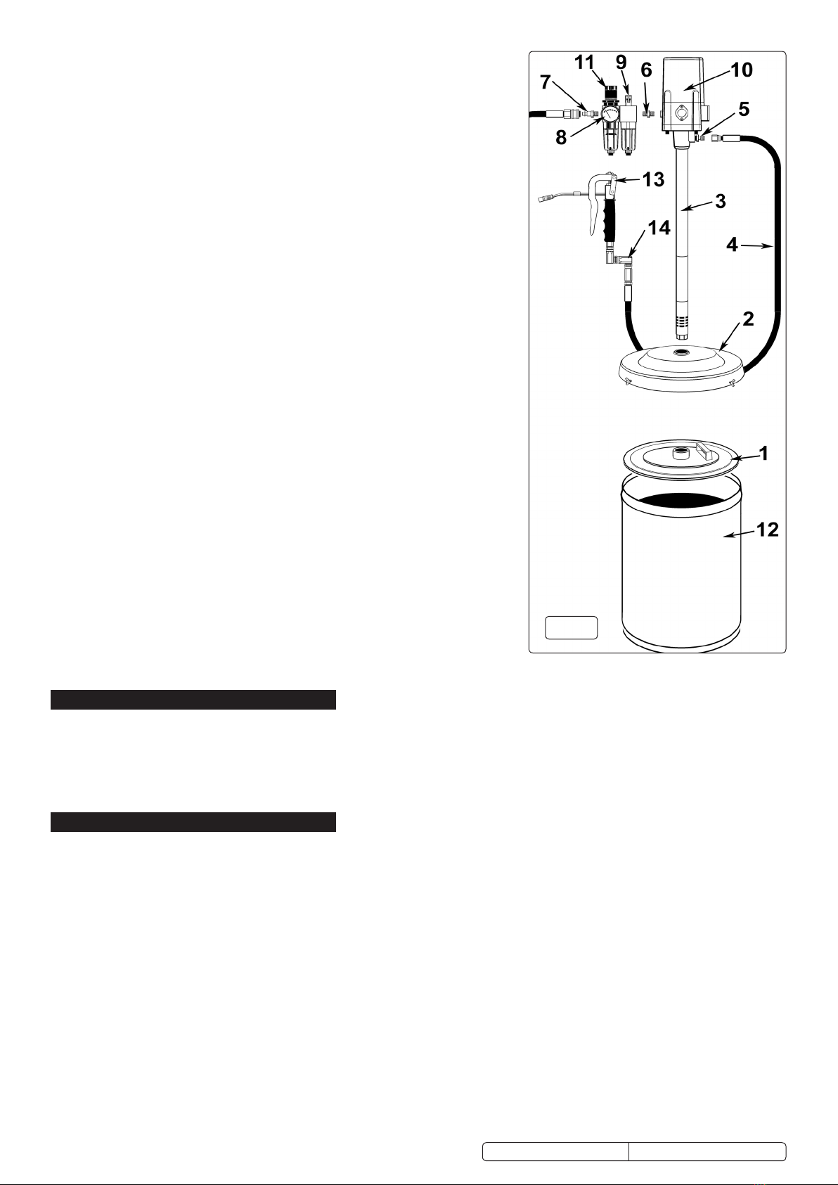
4.3.  Assemblingthepumpunit(refertofig.2).
WARNING! Clean new delivery lines ensuring all metal shavings have been
removed before connecting the pump and control valves. Any dirt in the inlet hoses
will damage the unit and may invalidate your warranty.
NOTE: It is recommended that PTFE sealing tape is used on all connections.
4.3.1. Place the grease bucket (12) onto the platform of the trolley.
4.3.2. Remove the original lid supplied with the grease bucket and store it for future use.
4.3.3. Insert the follower plate (1) into the top of the grease bucket (12) with the handle
uppermost and settle it down onto the surface of the grease. The follower plate
is drawn down by the suction of the air pump and compresses the grease during
operation to prevent air pockets.
4.3.4. Secure the grease bucket to the trolley by sliding the securing hook over the rim of
the grease bucket and locking with the hand screw.
4.3.5. Place the dust cover (2) onto the grease bucket (12), but do not secure.
4.3.6. Lower the pump assembly through the support bracket on the trolley.
4.3.7. Align the pump shaft (3) over the dust cover (2) and allow the shaft to pass through
the dust cover (2), and the follower plate (1) then sink down to the bottom of the
grease bucket (12).
4.3.8. Align the position of the trolley support bracket so that the pump shaft is vertical
and perpendicular to the trolley base and the support bracket is set to the correct
position.
4.3.9. Tighten the trolley support bracket hand screws and tighten the three butterfly
screws to secure the dust cover (2) to the grease bucket (12).
4.3.10. Connect the air regulator (11) and air oiler (9) together using the long bolts and
Nuts provided (The nuts slide into the recesses in the front and back of the
regulator body). Ensure that the air flow arrows moulded into the top of each unit
body are pointing in the same direction and that both arrows are pointing towards
the pump air inlet. The air oiler (9) should be situated between the air regulator (11)
and the pump (10).
4.3.11. Screw the circular pressure gauge (8) into which ever side of the regulator (11)
is most convenient for reading. Seal the unused mounting position using the
blanking plug provided.
4.3.12. Connect the regulator (11) assembly to the pump air inlet using the 1/4”BSP fitting
(6) provided.
4.3.13. Connect the Z-swivel (14) to the grease gun (13) and connect the grease hose (4)
to the Z-swivel (14). Connect the other end of the grease hose (4) to the grease
outlet (5) on the pump.
5. OPERATION
5.1. Turn the air pressure on and check there are no leaks in the system.
5.2. Adjust the air pressure using the air knob on top of the air regulator. Unlock the knob by pulling it upwards and turning it until the gauge
indicates the recommended operating pressure of 115psi. Push the knob down again to lock it. It is important to maintain the correct
operating pressure to ensure that the control valves and connectors are not damaged, and to prevent leakage in the delivery lines.
5.3. Prime unit by operating grease control valve until lubricant emerges from end of the gun. The unit is now ready for use.
5.4. When not in use, turn the air supply off and disconnect the unit from the air supply. Store in a safe, clean, dry, childproof location.
6. MAINTENANCE
WARNING! Disconnect the pump from the air line before attempting any service or maintenance. Replace or repair damaged parts.
Use genuine parts only. Non-authorised parts may be dangerous and will invalidate the warranty.
6.1. Air line lubricator. This unit is designed to automatically lubricate the pump through the air intake. The unit must be kept topped up
 withgoodqualityairoil(Sealeyref:ATO/500500mlsizeorAT/10001ltrsize).Toadjusttheoilowturntheoilregulatorscrewon
 thetopoftheunit.Turnanti-clockwisetoincreasetheowandclockwisetodecreasetheow.Theoilsuppliedtolubricatethepump
is minimal. For an initial setting turn adjusting screw on top of the unit fully home and then open by ¼ of a turn. To change and clean
 theoilunitunscrewthebowlandretainthesealingring.Empty,clean,re-lltomaximumlineandreplaceensuringthesealingringis
 ttedcorrectly.DO NOT overtighten the bowl. Contact your local Sealey service agent for parts and information.
6.2. Cleaning. Clean pump and air units with clean damp cloth. Mild detergents may be used to remove grease. DO NOT use solvents or
abrasives and DO NOT get the pump or air units wet.
6.3. For a full service, contact your local Sealey service agent.
WARNING! When exchanging a polycarbonate bowl ensure the suction tube is protected to avoid dirt particles being transmitted to a
new bowl. Always clean new delivery lines ensuring all metal shavings have been removed before connecting the pump and control
valves. Failure to do so may damage the unit and will invalidate your warranty.
Original Language Version
© Jack Sealey Limited
fig.2
AK452X.V4, AK453X.V3 Issue 3 (H, F) 06/07/18
7. TROUBLESHOOTING
Original Language Version© Jack Sealey Limited
FAULT CAUSE REMEDY
Air motor runs slowly or not at all. Air pressure is too low.
Mu󰀪erorlterisblockedordirty.
Adjust air pressure.
Removemu󰀪erand/orltercleanandreplace.
Air motor is running but pump is
too slow or not working at all.
Greaselterisblocked.
Grease viscosity too high.
Air pockets in grease container.
Grease container is dented
Removeandcleanlter
Move drum to warmer area to allow temperature of grease to rise above
15°C.
Viscosity too high. Temperature must be above 15°C. Compact the
grease by depressing the follower plate.
Push the follower plate past the dented area of the container.
Air motor is running but no
pressure is generated
'O' rings, washers or valves within pump are
damaged or dirty.
Clean or replace relevant components. Servicing by an approved Sealey
service agent recommended.
Airescapesfromthemu󰀪erwhen
the pump is not operating.
The plunger is damaged.
The 'O' rings or the distributor is damaged.
Replace plunger. Servicing by an approved Sealey service agent
recommended.
Replace parts using a complete repair kit.
AK452X.V4, AK453X.V3 Issue 3 (H, F) 06/07/18
Sealey Group, Kempson Way, Suffolk Business Park, Bury St Edmunds, Suffolk. IP32 7AR
01284 757500 01284 703534 sales@sealey.co.uk www.sealey.co.uk
ENVIRONMENT PROTECTION
Recycle unwanted materials instead of disposing of them as waste. All tools, accessories and packaging should be sorted, taken to
a recycling centre and disposed of in a manner which is compatible with the environment. When the product becomes completely
unserviceable and requires disposal, drain any fluids (if applicable) into approved containers and dispose of the product and fluids
according to local regulations.
Note: It is our policy to continually improve products and as such we reserve the right to alter data, specifications and component parts without prior
notice.
Important: No Liability is accepted for incorrect use of this product.
Warranty: Guarantee is 12 months from purchase date, proof of which is required for any claim.