manuals.online logo
Brands
  1. Home
  2. •
  3. Brands
  4. •
  5. Seametrics
  6. •
  7. Measuring Instrument
  8. •
  9. Seametrics IP80 Series User manual

Seametrics IP80 Series User manual

General Information
The IP80 Series are impeller-type insertion meters de-
signed for use in pipe sizes 1/2" to 8". High-quality jewel
bearings and nickel-bound tungsten carbide shaft are
used for maximum life and extreme low friction. Bodies
are machined from solid rod for maximum precision. Low-
flow performance is superior. The rotation of the rotor is
detected by a non-drag Hall-effect sensor. Output is a
pulse-type square wave, which can be sent long dis-
tances (up to 2,000 feet) without a transmitter. This sig-
nal can be connected directly to SeaMetrics controls, as
well as PLC's, counters, and computer cards.
SeaMetrics IP meters are ideal for chemical proportion-
ing applications. If no display is required, a simple di-
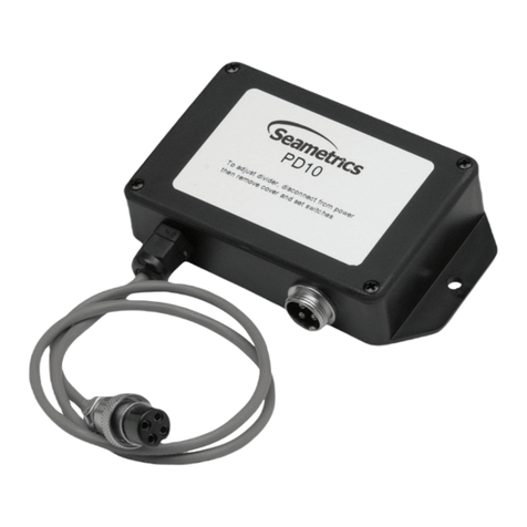
vider such as the PD10 provides adjustable pump pac-
ing. For rate and total display, as well as pump pacing,
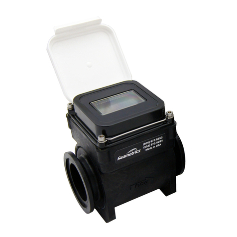
the FT415/420 flow indicator can be mounted directly
on the IP80 Series, or remotely on a wall or panel.
The IP80 Series require special fittings, since they are
not depth-adjustable as are the IP 100/200 series meters.
Installation in the fitting ensures correct depth placement
in the pipe. Fittings are available in PVC, brass, and
stainless steel. Sensors are available in brass, 316 stain-
less steel, PVC, and polypropylene. In plastic pipe
3"-8", use an IP82 sensor, which is 1.00" longer than the
IP81 to accommodate the larger fittings.
Features
IP80 Series Flow Sensor
Instructions
LT-10610A
Page 1 of 4
High level (12 VDC)
signal can be sent
up to 2000+ feet
without transmitter
Each fitting individually
calibrated and marked
with K-factor
(Pulses per Gallon)
Fitting automatically
sets probe at correct
depth and orientation
Jewel bearings for
superior low-flow
performance.
Threaded housings
allow for field repair
Meter mount option
for electronics:
FT415/420 (Rate/Total)
AO55 (4-20 mA)
PD10 (Divider)
MODEL
SERIAL
Specifications
Sensor
Hall Effect Sensor 12 VDC current sink-
ing pulse
Materials
Sensor Body PVC, Polypro, Brass,
or 316 SS
Rotor Kynar
ShaftNickel-bound
tungsten carbide,
ceramic optional
Bearings Ruby jewel
Maximum Pressure
PVC 175 PSI (12 bar) at 75°*
Polypro175 PSI (12 bar) at 75°*
Brass 200 PSI (14 bar)
316 SS 250 PSI (17 bar)
Maximum Temperature
PVC,Polypro 130°F (55°C)*
Brass, SS 200°F (93°C)
Accuracy1-1/2% FS
Flow Range (GPM)
1/2" 3/4" 1" 1-1/2" 2" 3" 4" 6" 8"
Min 0.28 0.5 0.8 1.9 3.1 6.9 12 27 47
Max 28 50 80 190314691120027004700
Cable#22 AWG 3-con, 18'
* (see Pressure vs. Temperature chart)
Spec Tech Industrial 203 Vest Ave. Valley Park, MO 63088 Phone: 888 SPECTECH
Email: [email protected] www.spectechind.com
Installation
Fitting Installation. IP80 Series meters require spe-
cialfittings. Themeterfitting must first be installed in the
pipeline. Straight pipe of at least ten times the diameter
upstream of the meter and five diameters downstream
are strongly recommended. Inadequate straight pipe,
especially downstream of an elbow, change in pipe di-
ameter, or partially-opened valve, can result in signifi-
cant inaccuracy. Typically this inaccuracy is in the form
of the meter reading high. Some IP80 Series meter fit-
tings are supplied with upstream straight pipe.
Meter Installation. After the meter fitting is installed in
thepipeline,themetercan beinstalledin thefitting. Press
the meter into the fitting as far as it will go. Then retain
the meter in place by inserting the u-pin. This pin
canbe installed from eitherside. It is sometimes neces-
sary to rotate the probe back and forth slightly to start
the pin into the slots on the probe. Slide the pin in as far
as it will go.
Meter Connection. Seethe“IP80SeriesConnections”
diagramformeterconnections. Unlessthemeterissup-
pliedpre-connectedtoameter-mounted FT415/420 flow
indicator, three leads must be connected. These three
leads are color coded. The red wire is 6-24 VDC posi-
tive, the black is negative, and the white wire is the sig-
nal lead.
2 of 4
10 5
Diameters Diameters
Red (+)
White (SIG)
Black (-)
These water meters are not recom-
mended for installation downstream of
theboilerfeedwater pump whereinstal-
lation fault may expose the meter to
boilerpressureandtemperature.Maxi-
mumrecommendedtemperatureis 130ºF (Plastic),
200ºF (Metal).
!
IP80 Series Connections
In the larger sizes, the length provided is less than ten
diameters upstream and five downstream. It is not ad-
visable to connect directly to the end of these fittings
withaflow-disturbingdevice such as a valve or elbow. If
possible, straight pipe should be added to these fittings.
A PVCfittingisusually installed by solvent welding. The
stainless steel and brass meter fittings have female pipe
threads,requiringtheappropriatemalethreadedfittings.
Saddle fittings (size 3" and above) require a hole to be
cut in the pipe. The recommended hole size is 1-3/4".
BEST
Okay, if no air in pipe
Okay, if no sediment
in pipe.
K-factor. If the IP80 Series meter is ordered with its
fitting, the meter is factory calibrated in the fitting. A K-
factor (meter factor) is indicated on the side of the fit-
ting. This represents the actual number of pulses per
gallon the meter produced during the factory flow test.
This number can entered into an FT415/420 or FT5210
flow indicator to make it read properly. If a pulse divider
is being used, the K-factor is the starting point for calcu-
lating the divider number.
!
Caution: Never remove the u-
clip retainer when the pipe is
underpressure. Alwaysremove
pressure from the pipe before
attempting to remove the meter.
Removal under pressure may result in damage
or serious injury.
Troubleshooting Guide
Problem Probable Cause To Check To Repair
No signal after installation Insufficient flow See Min. GPM for size Contact SeaMetrics
Bad connections to control
electronics
Check connections at control.
Check polarity: red (+), black (-),
white (signal) Re-connect if necessary
Incompatible control Does control: 1) provide 6-24VDC
power; 2) accept current sinking
inputs Contact SeaMetrics
Damaged or missing rotor Remove meter and check visually
for free spinning Obtain new rotor and replace
Inaccurate metering Not enough straight pipe between
meter and flow disturbance See recommendations, measure Move meter away from flow
disturbance or field calibrate
Maintenance and Repair
3 of 4
Rotor Replacement. Rotors are easily field-replaced.
Shaft and rotor are a single unit, and are not replaced
separately. If replacement is due only to normal shaft
wear, bearing replacement is probably not necessary.
If the rotor has been damaged by impact, the bearings
should also be replaced. Rotor and bearings can be
ordered as a kit, Part No.25901. Follow these steps:
1. Unscrew the threaded bearing housings to expose
the shaft ends. If bearings are being replaced, back
them completely out.
2. Remove the rotor. Put the new rotor in its place.
3. Thread in one bearing housing part way, then the
other. Take care to start the end of the shaft into the
bearing hole before tightening further.
4. Screw in bearing housings until they bottom. Note:
Do not use excessive force.
5. Checkforfree spin. Blowinglightlyonthe rotorshould
result in it spinning rapidly and coasting to a smooth
stop.
Sensor Replacement. It is very unusual for a sensor
torequirereplacement in normaluse. Theprimarycause
of sensor failure is overvoltage (inadvertent connection
of line voltage, for example) or incorrect polarity on
hookup. The sensor is replaced by removing the the
strain relief, then threading out the sensor retainer plug.
Removethe entiresensorcapsuleby pullingonthe cable.
The new sensor capsule can then be installed. It is impor-
tant to orient the sensor capsule properly. Replace the re-
tainer plug, and then replace and tighten the strain relief.
1
65
27
3
4
7
8
9
10
11
12
14
13
MODEL
SERIAL
11
20419 80th Ave. So., Kent, WA 98032 USA
Phone: 253-872-0284 Fax: 253-872-0285
www.seametrics.com 1-800-975-8153
4 of 4
* Consult distributor or price pages
gnitsiLstraPseireS08PI
1gnisuohreppU18162
2teksaG11262
3gnisuohrewoL03992
4wercsgnisuoH92262
5leets,gulP37062
6citsalp,gulP97062
7feileRniartS5567
8reniateRrosneS12352
9rosneS01362
01ydoB*
11)2(ylbmessagniraeB10952
21gnir-O18052
31rotoR03111
41gnittiF*
trahCytilibitapmoCsgnittiF
lairetaM18PI28PI
eznorBeeT"4-"1gnittifezarB"8-"3
CVPeeT"2-"2/1elddaS"8-"3
orpyloPA/NeeT"8-"3
leetssselniatSeeT"2-"2/1gnittifdleW"8-"3
leetsnobraCeeT"2-"2/1gnittifdleW"8-"3

This manual suits for next models

2

Other Seametrics Measuring Instrument manuals

Seametrics WMX SERIES User manual

Seametrics

Seametrics WMX SERIES User manual

Seametrics EM101 User manual

Seametrics

Seametrics EM101 User manual

Seametrics INW User manual

Seametrics

Seametrics INW User manual

Seametrics jWAVE User manual

Seametrics

Seametrics jWAVE User manual

Seametrics EX90 User manual

Seametrics

Seametrics EX90 User manual

Seametrics iMAG 4700 User manual

Seametrics

Seametrics iMAG 4700 User manual

Seametrics WTP-400 User manual

Seametrics

Seametrics WTP-400 User manual

Seametrics AG3000 Series User manual

Seametrics

Seametrics AG3000 Series User manual

Seametrics AG90 User manual

Seametrics

Seametrics AG90 User manual

Seametrics WMP-Series User manual

Seametrics

Seametrics WMP-Series User manual

Seametrics FT400 User manual

Seametrics

Seametrics FT400 User manual

Seametrics FT400 User manual

Seametrics

Seametrics FT400 User manual

Seametrics AG3000p User manual

Seametrics

Seametrics AG3000p User manual

Seametrics jWAVE User manual

Seametrics

Seametrics jWAVE User manual

Seametrics FT420 User manual

Seametrics

Seametrics FT420 User manual

Seametrics PD10 User manual

Seametrics

Seametrics PD10 User manual

Seametrics EX11 Series User manual

Seametrics

Seametrics EX11 Series User manual

Seametrics MDE User manual

Seametrics

Seametrics MDE User manual

Seametrics S Series User manual

Seametrics

Seametrics S Series User manual

Seametrics iMAG 4700 User manual

Seametrics

Seametrics iMAG 4700 User manual

Seametrics MJ Series User manual

Seametrics

Seametrics MJ Series User manual

Seametrics FT400 Configuration guide

Seametrics

Seametrics FT400 Configuration guide

Seametrics WMP Series User manual

Seametrics

Seametrics WMP Series User manual

Seametrics FT430 User manual

Seametrics

Seametrics FT430 User manual

Popular Measuring Instrument manuals by other brands

CAPTELEC M 3530 quick start guide

CAPTELEC

CAPTELEC M 3530 quick start guide

Twilight MC-SUP2000H manual

Twilight

Twilight MC-SUP2000H manual

HunterLab ColorFlex EZ Supplemental manual

HunterLab

HunterLab ColorFlex EZ Supplemental manual

Sekonic L-608 CINE operating manual

Sekonic

Sekonic L-608 CINE operating manual

Abaxis VetScan UA10 manual

Abaxis

Abaxis VetScan UA10 manual

2B Technologies OEM-106-H Operation manual

2B Technologies

2B Technologies OEM-106-H Operation manual

EzCAP ezcap271 quick start guide

EzCAP

EzCAP ezcap271 quick start guide

Bosch GLM 80 Original instructions

Bosch

Bosch GLM 80 Original instructions

PCB Piezotronics M320C52 Installation and operating manual

PCB Piezotronics

PCB Piezotronics M320C52 Installation and operating manual

PCB Piezotronics 338C04 Installation and operating manual

PCB Piezotronics

PCB Piezotronics 338C04 Installation and operating manual

Ulvac GI-M2 Quick manual

Ulvac

Ulvac GI-M2 Quick manual

AquaLabo TOXmini operating manual

AquaLabo

AquaLabo TOXmini operating manual

Zoetis AlphaTRAK Instructions for use

Zoetis

Zoetis AlphaTRAK Instructions for use

Vigor V3748 operating instructions

Vigor

Vigor V3748 operating instructions

Bacharach Fyrite INTECH quick start guide

Bacharach

Bacharach Fyrite INTECH quick start guide

SATO KEIRYOKI SK-5RAD-MR instruction manual

SATO KEIRYOKI

SATO KEIRYOKI SK-5RAD-MR instruction manual

PCB Piezotronics W138A50/038CY020AC Installation and operating manual

PCB Piezotronics

PCB Piezotronics W138A50/038CY020AC Installation and operating manual

Tettex MIDAS 2881 operating instructions

Tettex

Tettex MIDAS 2881 operating instructions

manuals.online logo
manuals.online logoBrands
  • About & Mission
  • Contact us
  • Privacy Policy
  • Terms and Conditions

Copyright 2025 Manuals.Online. All Rights Reserved.