Sears CRAFTSMAN POWER WASHER 900 User manual

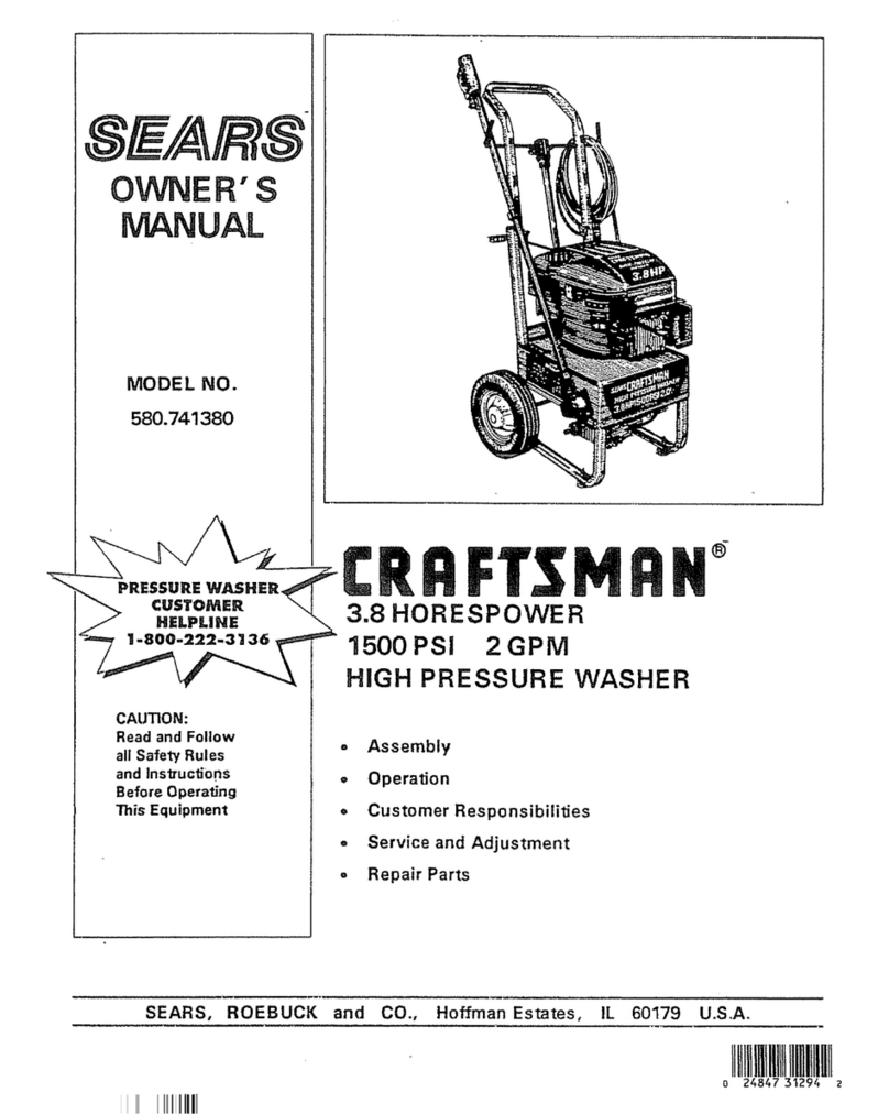
OWNERS
MANUAL
MODEL
NO.
559.72355
CAUTION
READ AND FOLLOW
ALL SAFETY RULES
AND INSTRUCTIONS
BEFORE OPERATING
THIS UNIT.
·.
~!EA'Rl~
I
CRAFTSMAN@
POWER
WASHER
900
9 Assembly
e Operation 9 Maintenance
9 Repair Parts
Sold by Sears, Canada Inc
.,
Toronto, Ontario M5B-2B8
OWNERS MANUAL PART NO. 4.950-711

One Year Limited Warranty on Craftsman Power Washer 900
For one year from the date of purchase, when this Craftsman Power Washer is maintained and operated according to
the instructions in the owner's manual, Sears will repair,free ofcharge, any defect
in
material and workmanship.
If this Craftsman Power Washer 900 is used for commercial or rental purposes, this warranty applies for only 30 days
from the date of purchase.
This warranty does not cover:
-Repairs necessary because of operator abuse or negligence.
WARRANTY SERVICE
IS
AVAILABLE BY RETURNING THE CRAFTSMAN POWER WASHER 900 TO THE
NEAREST SEARS AUTHORIZED SERVICE DEPOT (PAGE 9).
This warranty is
in
addition to any statutory warranty.
SEARS, CANADA INC., TORONTO, ONTARIO, M5B-2B8
TABLEOFCONTENTS
Page
WARRANTY
........
............
....
...
..
.......
2
SAFETY RULES & PRECAUTIONS
.............
3
KNOW YOUR POWER WASHER
...............
4
Operating Instructions
....
..................
5
Cleaning Method .......... ... ... .. ........ . 7
Page
SPECIAL ACCESSORIES ........ ...... .. ..... 8
SERVICE DEPOTS ........... ... ....... ....... 9
MAINTENANCE .. ..... ....... .. .... .. ......... 10
TROUBLE SHOOTING ... ....... ... ... .. ..... . 10
PARTS LIST
.......................
.
..........
11
SPECIFICATIONS
Length I width I height
Weight not including accessories
Connected load
Drive power
Capacity
Working pressure
Max. water supply temperature
Cleaning chemical intake
Suction height with cold water
(Nozzle 6.415-515)
1.
High-pressure hose
2.
Trigger gun
3.
Spray wand
4.
Changeover nozzle
5.
Washing brush
6. Cleaning agent suction
hose with filter
7. Plug
8.
Oil level
in.
lbs
Hp
Hp
GPM
psi
OF
GPH
ft
.
16" / 5
1/2''
/
91
/2''
25
1.6
1.1
1.8
900
140
9.
Pressure gauge
10
. Strainer
11.
Water connection
12. Connection for
cleaning-agent hose
13.
High-pressure connection
14.
Cleaning-agent adjustment
valve
15.
Switch
MODEL
NUMBER~~~~55~9~.7~2=3~5~5~~~-
SERIAL
NUMBER
____________
_
THE MODEL AND SERIAL NUMBER WILL BE
FOUND ON THE DECAL.
YOU SHOULD RECORD BOTH MODEL AND
SERIAL NUMBERS AND KEEP
IN
A SAFE
PLACE FOR FUTURE REFERENCE.
A Instructions given with this symbol
are for personal safety.
Be
sure to
follow them.
1+
-+-f.1
I v
,,
I
fZ1
U2
U2
(l
Z2
I
fl
I .
I I
L_.
__
.J
2
Circuit
diagram
C1
Running capacitor
F1
Overload protection
M1
Motor
S1
Switch
115 v
1-60
Hz
lJ

SAFETY
RULES AND PRECAUTIONS
Failure to follow Safety Rules &Precautions could result
in
serious injury
Important: This manual should be read thoroughly before attempting to assemble or operate.
Keep this manual
in
a safe place for future reference orfor ordering replacement parts.
RULES FOR SAFEOPERATION
1. Risk of electrocution
-Connect only
to
properly grounded outlet.
Do
not remove ground
pin.
-Inspect cord before using.
Do
not use
if
cord
is
damaged.
-Keep
all
connections dry and off the ground.
-
Do
not touch plug with wet hands.
-Read instructions before using.
2. Keep away from children.
3.
Do not spray against any other person.
4. Use of protective glasses is recommended.
5.
Manufacturer takes no liability for any dama-
ges incurred by the use ofthe Power Washer.
Grounding instructions
This product must
be
grounded.
If
it should malfunc-
tion or breakdown, grounding provides a path of
least resistance for electric current to reduce the risk
of electric shock. This product
is
equipped with a
cord having
an
equipment-grounding conductor and
a grounding plug. The plug must
be
plugged into
an
appropriate outlet that
is
properly installed and
grounded
in
accordance with
all
local codes and or-
dinances.
Danger -Improper connection at the equipment-
grounding conductor can result
in
a risk of electrocu-
tion. Check with a qualified electrician or service per-
son, if you are
in
doubt
as
to whether the outlet
is
properly grounded.
Do
not modify the plug provided
with the product -if
it
will not fit the outlet, have a
proper outlet installed
by
a qualified electrician.
3
Extension cords
Use only 3-wire extension cords that have 3-prong
grounding-type plugs and 3-pole cord connectors
that accept the plug from the product. Use only ex-
tension cords that are intended for outdoor use.
These extension cords are identified by a marking
"Acceptable for use with outdoor appliances; store
indoors while not
in
use." Use only extension cords
having
an
electrical rating not less than the rating of
the product. (See
pg.
4 for reccomended cord speci-
fications.)
Do
not use damaged extension cords. Ex-
amine extension cord before using and replace
if
damaged.
Do
not abuse extension cord and do not
yank
on
any cord
to
disconnect. Keep cord away
from heat and sharp edges. Always disconnect the
extension cord from the receptacle before discon-
necting the product from the extension cord.
AWARNING!A
Do
not use any attachment or accessory with this
unit other than those sold specifically for use with
this unit. To do
so
could result
in
damage to the
unit or serious injury to the user/bystander. Keep
this manual
in
a safe place for future reference.

KNOW YOUR POWER WASHER
900
Important notes
1. Before using the Power Washer please review
the following procedures:
-Once unit has been removed from carton in-
spect
it
carefully for damages. Should you dis-
cover any damages please notify your local
SEARS RETAIL or CATALOGUE OUTLET.
2.
Electrical connection
The Power Washer 900 operates
on
115 volt
electricity. Before plugging unit
in,
please ensure
the following:
-Power socket being used must
be
protected
by
a
15
A or 20 A breaker.
-When using
an
extension cord observe the
specifications below.
Cable length Wire gauge
Up
to
33
ft.
14/3AWG
33 to 66
ft.
12/3
AWG
Important:
When using
an
extension cord always unwind
cord completely. Never leave coiled.
All
electrically live components
i.
e.
equipment,
electrical cable, plugs, etc., must
be
protected
against water splashes.
3.
Water supply
-Water hose must
be
at least
112
inch inside di-
ameter.
-The flow rate of the water supply must not fall
below 2 GPM (gallons per minute).
-Flow rate can
be
determined
by
running the
water for one minute into
an
empty 5 gallon
container. A minimum of 2 GPM
is
required.
-Water can also
be
drawn from a standing water
supply such as a lake or a drum by means of
suction.
-The water supply temp. must not exceed
140°F.
4
Important:
100"F
80
60
40
20
0
The Power Washer
is
not designed for suction of li-
quids containing such solvents
as
gasoline, paint
thinners, oil, etc.

Operating Instructions
1. To start
-Machine must
be
in
off position.
-Connect spray wand
(3)
to trigger gun (2).
--
""""'
~"1=--~
-Screw the high-pressure hose (1) to the high-
pressure connection (13).
-Connect a water hose to the water inlet fitting
(11)
on
the machine.
-Connect the other end of the water hose to
your water faucet.
'
r;
l\
~
A·
i
uf
'"
-Insert the plug (7) into the power socket.
e=--
-Turn the water faucet
on
full.
-Release the safety lock
on
the trigger gun (2).
2
-Press the trigger.
-Switch
on
the power washer.
'b
~
~
' :
-
In
the event of a lengthy break (more than 15 min-
utes) switch machine off to prevent overheating.
Refer to page 2 for illustration reference numbers.
5

2.
Spray pressure settings
High-pressure -Low-pressure
-To alter angle and pressure of the water jet,
turn changeover nozzle (4)
180
°.
15° High-pressure
40°
Low-pressure
3. Suction operation
-When drawing water from a lake or drum, you
must use a suction hose with filter.
-For water up to 86° F the suction height must
not exceed a maximum of 3.3
ft.
~
~
Cold-wat°'
suction hose
J~
~
;1
-----
Filte<
~
t~l------
::;;:J
'----
-When sucking water at temperatures between
86°-140° F the Power Washer must
be
situ-
ated at the same height as the water level.
4.
Spraying cleaning agent
Plug the cleaning-agent hose into the clean-
ing-agent connection
on
the cleaner
anc;J
turn
it
slightly to secure
it.
-Drop cleaning-agent suction hose
(6)
into
cleaning-agent container.
-Position changeover nozzle
(4)
to
"CHEM".
-The cleaning-agent intake can
be
adjusted by
turning the cleaning-agent adjustment valve
(14).
Tabel I
Valve setting 1 2 3 4
Cleaning agent
in
jet(%)
0.5-1.5
1.5-2.9
2.9-4.6
4.6-6
-Press trigger gun.
-Following completion of cleaning, suspend
cleaning-agent suction hose
(6)
in
a container
filled with
"clean"
water and flush through sys-
tem.
Refer to page 2 for illustration reference numbers.
6

5.
Attachment of washing brush
When attaching brush,
-switch off Power Washer
-turn off water supply
-set changeover nozzle (4) to "CHEM"
-attach brush to spray wand.
...---
-The spray wand can be inserted into the gun
in
6
different positions.
~
~J
~
-Following removal of the spray wand, the washing
brush can also be attached directly to the gun.
6. After use
-Flush device after spraying cleaning agent.
-Shut off water supply from faucet or,
in
the case of
suction operation, remove suction hose from
bucket.
-Squeeze trigger of gun until no further water
emerges.
-Release trigger and secure with catch.
-Switch off Power Washer.
-Remove plug from socket.
Cleaning method
1.
step: Loosen dirt
-Set cleaning-agent adjustment valve (14)
to accommodate the degree of soiling.
-Set nozzle (4) to
"CHEM"
and apply
cleaning-agent solution.
-Allow
1-5
minutes for cleaning agent to
react.
-Only use
"max"
setting
in
the event of ex-
treme soiling, e.g. for cleaning sanitary
facilities and swimming-pools.
2.
step: Remove dirt
:--
Wash off loosened dirt using high-pres-
sure.
Vehicle cleaning with Sears Power Washer 900.
1.
step: Apply cleaning agent using low-pressure
jet (40°).
2.
step: Wash off using max. water volume and
high pressure jet (15
°).
3.
step: Apply drying agent
-Drying agent must be applied without
pressure. To do this spray wand must be
removed from the gun.
Refer to page 2 for illustration reference numbers.
7

SPECIALACCESSORIES
Pas. Special accessories
1 Underbody lance
2 Washing brush
3 Dirt Blaster for large,persistant stains
4 Triple nozzle with lance (point jet0
°,
flat jet 25
°,
low pressure jet 45
°)
5 Extension for spray lance
7 Pipe cleaning accessory/attachment
9 Accessory set for pumping water and wate
ri
ng
plants
10
Transport carriage
Cold-water suction hose with filter, 3 m
amn:n
-
~-~----
-
G)
•
•
®
® ,
'/.:
:
-
Accessories are available at most authorized service depots.
8
Order No.
4.760-122
4.762-046
4.763-097
4.760-159
4.760-178
2.637-367
2.637-214
6.541-040
4.440-238

AUTHORIZED SERVICEDEPOTSIN CANADA
ONTARIO
Karcher Cleaning Systems Inc.
1770Alstep Drive, MISSISSAUGA, Ontario L5S 1W1, Tel. (416) 672-8233 ·Fax (416) 672-3155
ATLANTIC REGION
Karcher Cleaning Systems Inc.
390 Rothesay Avenue,
P.
0 . Box 640, SAINTJOHN, New Brunswick E2L 4A5, Tel. (506) 634-1866
·Fax
(506) 634-8983
BRITISH COLUMBIA
Karcher Cleaning
Systems
Inc.
106-86 North Bend Street, COQUITLAM,
B.
C. V3K 6H1, Tel. (604) 464-8348 ·Fax (604) 464-8923
ONTARIO
Karcher Cleaning
Systems
Inc.
1770 Alstep Drive, MISSISSAUGA, Ontario L5S 1W1, Tel. (416) 672-8233
·Fax
(416) 672-3155
SASKETCHWAN
Karcher Cleaning Systems Inc.
155 North Leonard Street, REGINA, Saskatchewan S4N 5X5, Tel.
(3
06) 721-2516
·Fax
(306) 721-2526
MANITOBA
Karcher Cleaning Systems Inc.
3-170 Murray Park Road, WINNIPEG, Manitoba R3J 3X5, Tel. (204) 832-2499
·Fax
(204) 832-2487
ALBERTA
W.E. Greer Ltd.
14704-119Avenue
EDMONTON, Alberta
T5L
2P1
Tel. (403) 451-1516
Telex (037) 41414
Fax (403) 451-0334
W.E.
Greer
Ltd.
421
Manitou Road, S.E.
CALGARY, Alberta, T2G 4C2
Tel. (403) 243-7831
Telex (038) 27794
Fax (403) 287-0477
W.E. Greer Ltd.
9625-115 Street
GRANDE PRARIE, Alberta
T8V 5Z6
Tel. (403) 532-8766
W.E. Greer Ltd.
105-315 MacDonald Crescent
FORT McMURRAY, Alberta
T9H 4B7
Tel. (403) 791-3466
ONTARIO
Flexo Products (Niagara) Ltd.
4777 Kent Avenue
NIAGARA FALLS, Ontario
L2H 1J5
Tel. (416) 354-2723
Fax (416) 354-1301
Swish Maintenance Limited
309 Lansdowne Street East
P.
0.
Box778
PETERBOROUGH, Ontario
K9J 7A2
Tel. (705) 745-5763
Fax(705)745-0220
Swish Maintenance Limited
1501 Hopkins Street South
WHITBY, Ontario
L1N 2C2
Tel. (416) 666-1224
Swish Maintenance Limited
700 Development Drive
KINGSTON, Ontario
K7M4W7
Tel. (613) 384-2410
9
Swish Maintenance Limited
864 Clyde Avenue
OTTAWA, Ontario
K1Z5A2
Tel. (613) 728-0009
Swish Maintenance Limited
40 Belfarm Road, Unit 5
BARRIE, Ontario
L4M 5G6
Tel. 1-800-461-5478
QUEBEC
Larose & Fils Ltee
Karcher Divison
1991 ouest Autoroute Laval (440)
LAVAL, Quebec
H7L3W3
Tel. (514) 682-5005
Larose & Fils Ltee
2255 boul. lndustriel
CHOMEDY, LAVAL, Quebec
H7S 1P8
Tel. (514) 382-7000
Telex (05) 267440
Fax (514) 667-8515
Larose & Fils Ltee
1990 boul Charest ouest
STE. FOY, Quebec
G1N4K8
Tel. (418) 683-7000
Larose & Fils Ltee
41
ave. Gagnon C.P.
91
MONT-JOLI, Quebec
G5H3K8
Tel. (418) 775-4482

MAINTENANCE
Before servicing the Power Washer disconnect the
plug from the electrical power supply, and shut off
the water supply.
1.
Changing the oil
The oil should
be
changed once a year, or after
approx. 400 hours of operation. First the oil-level
sight glass
(8)
is
removed. The old oil
is
then
drained and 0.2 liter of new oil (15W-40, Order
No.
6.288-050 from service depots)
is
poured
in.
2.
Repairs
Any repairs that may
be
necessary should
be
en-
trusted to authorized service technicians. Please
send the unit with its accessories to the nearest
authorized service depot.
3.
Protection against Freezing
The Power Washer must
be
stored
in
such a way
as to protect it from freezing.
Do
not store the Power Washer outdoors
where the temperature
is
below 32°
F.
4.
High-pressure hose
The high-pressure hose must conform to safety
regulations, and must
be
marked with the max-
imum permissible operating pressure, the date of
manufacture and the name of the manufacturer.
Karcher high-pressure hoses meet these require-
ments.
5.
Safety device
If
the pressure
is
excessive, the relief valve
on
the
pump opens a bypass on the pump intake side;
the factory setting must not be changed.
6. Cleaning changeover nozzle
Disconnect
th
e spray wand
(3)
from the trigger
gun
(2)
.
Remove dirt from nozzle bore with needle and
rinse with water from nozzle end.
In
the event of
stubborn dirt, disassemble changeover nozzle.
7.
Dismantling the changeover nozzle
Lift out the clip
(1
),
using a narrow screwdriver.
Pull off the cover
(2).
Unscrew the sleeve nut (3), using a 13/16" open-
ended wrench; use a
11
/16" open-ended spanner
to hold the end of the changeover nozzle.
Remove the sleeve nut; when doing this, hold the
spray wand with the nozzle uppermost to prevent
the ball
(4)
from becoming lost.
Press the nozzle tip
(5)
out of the sleeve nut
(4),
and clean
it.
Reassemble by proceeding
in
the reverse of the
above sequence.
TROUBLE SHOOTING
Symptom
Problem
Correction
1.
Device will not start 1. No electrical power supply available ChecK cable, plug, power socket and fuse
2.
Motor overheats Press trigger of gun;after approx. 2 minutes the thermal
protection switch will switch the motor back on
3.
Low voltage
4. Trigger not open Open trigger
5. Electrical defect Have device repaired by service depot
2.
Device does not come 1. Pump is sucking air Check water hose, turn on water supply
up to pressure 2. Water filter clogged Clean filter
3.
Pump not bled to remove air Switch off device, press trigger of gun, switch on
device while pressing the trigger; repeat
if
necessary
4. Pump or relief valve defective Have device repaired by service depot
3. Water jet irregular 1
. Nozzle clogged Clean nozzle
2.
Water supply inadequate Use device in suction operation with open container
3. Relief valve incorrectly set Have device repaired by service depot.
4.
Water jet cannot be
1.
Ball in changeover nozzle stuck Tap changeover nozzle lightly;
varied degrease the nozzle
5.
No intake of cleaning
1.
Suction filter clogged Clean filter
in
suction nozzle
agent
2.
Nozzle blocked Clean changeover nozzle
3,
Ball
in
cleaning agent non-return Disconnect suction hose (6), and insert a piece of thin wire into the
valve jammed intake aperture until the ball in the valve is freed; reassemble device
4.
Wrong nozzle setting Switch the changeover nozzle to low pressure
10
SEARSI CRAFTSMAN
POWER WASHER MODEL
559.
72355
COMPONENT PARTS
REF. NO.
1
2
3
4
5
6
7
8
9
10
11
12
13
14
15
16
17
18
19
21
16
~~
~
17
15'ij
14
10
18
~
5 4
!!>--.
r
19
SPARE PARTS LIST
PART NO. DESCRIPTION
6.631-267 PROTECTING CAP
6.631-305 SWITCH WITH CAP
5.321-245 HANDLE
6.641-922 CABLEWITH PLUG
6.303-114
SCREWM4x10
6.641-367 COUNTERNUT
PG
11
6.661-136 CAPACITOR 60µF
5.263-037 CLAMP ELEMENT
5.365-138 PROFILE
SEAL
5.066-360 CAP
6.303-082 OVAL HEAD SCREW M4 x 8
5.057-037 SUPPORT
5.066-267 CAP
6.303-102 OVAL HEAD SCREW M4 x 16
6.414-277 FILTER
6.388-216 FLEXIBLE TUBE NW5
6.303-101 OVAL HEAD SCREW
MS
x 16
6.641-668
CABLECONNECTORPG11
6.641-804 CLAMPING DISK
7.312-163 CROWN GEAR
11
QTY.
1
1
1
1
1
1
1
2
1
1
1
4
1
1
1
1
6
1
1
1

PUMP PARTS
5
SEARSI
CRAFTSMAN
POWERWASHER MODEL
559.
72355
39
12
OL
OIL
HUILE 56

REF. NO.
-
5
7
s
9
10
11
12
13
14
15
16
17
1S
19
20
21
22
23
24
25
26
27
2S
29
30
31
32
33
34
35
36
37
3S
39
40
41
43
44
45
46
47
4S
49
50
51
52
53
54
55
56
5S
59
SEARS/CRAFTSMAN
POWER WASHER MODEL
559.
72355
PART NO.
5.411-072
6.362-079
5.553-176
6.362-375
5.332-207
6.362-169
5.5S1-103
5.305-146
6.421-123
6.362-07S
4.5S0-1SO
6.362-4SO
5.5S3-10S
6.304-016
5.060-340
5.030-533
5.332-209
5.5S2-0SO
6.362-097
6.365-322
5.115-3S5
5.115-425
6.365-321
6.362-101
5.411-064
5.030-500
5.332-206
5.553-1S4
6.362-365
5.291-032
4.321-052
6.362-561
5.060-336
6.303-07S
5.364-129
4.401-052
6.414-252
6.304-017
6.362-4S1
5.5S1-104
5.5S2-073
5.332-249
5.769-0S7
6.362-3S4
5.332-124
7.401-909
6.362-3S3
5.446-005
4.550-120
6.2SS-050
6.362-362
5.443-300
PUMP PARTS
SPARE PARTS LIST
DESCRIPTION
SCREW PLUG
0-RING
1S
x 2.5
PISTON
0-RING
COMPL.
COIL SPRING
0-RING
12.0 x 2.0
VALVE SEAT
SPECIAL SCREW
MANOMETER
0-RING
13.3 x 2.4
VAL
VE COMPL.
0-RING
12.42 x 1.7S
VALVE SCREW
CHEESE HEAD SCREW
HOUSING
MOULDING
COILSPRING
VALVE DISK
0-RING
S5
x 3
PACKING RING 16 x 24 x 7
WASHER
DISK
PACKING RING 16 x 24 x 5
0-RING
S x 2
SCREW PLUG
MOULDING
COIL SPRING
PISTON
0-RING
COMPL.
SPINDLE
HANDLE
0-RING
50 x 2
COVER
CHEESE HEAD SCREW
MS
x 20
FLAT
PACKING
SCREW UNION
STRAINER
CHEESE HEAD SCREW
MS
x 50
0-RING
14 x 2
VALVE SEAT
VALVE HEAD
COIL SPRING
NOZZLE INSERT
0-RING
9 x 1.5
COIL SPRING
STEEL
BALL
0-RING
6 x 2
HOUSE COUPLING
CYLINDER HEAD
ENGINE OIL
0-RING
HOSE STEM
13
OTY.
1
1
1
1
1
1
1
1
1
3
3
3
2
2
1
1
1
1
1
3
3
3
3
1
1
3
3
3
1
1
1
1
1
4
1
1
1
4
3
3
3
3
1
2
1
1
1
1
1
1 L
1
1

MOTOR
REF.
NO.
0
1
2
3
4
5
7
8
9
11
12
13
15
16
SEARSI CRAFTSMAN
POWER WASHER MODEL
559.
72355
0 5
4
15
13
16
12
11
SPARE PARTS LIST
PART NO. DESCRIPTION
4.623-056 MOTOR
7.401-115
BALL
BEARING 6002-2rs
6.343-026 TOLERANCE RING
32
x 6
5.063-330 COVER
6.303-076 CHEESE HEAD SCREW M5 x 20
5.600-018 RUNNING WHEEL
4.120-128 SWASH PLATE
5.015-044 PROFILE RING
6.401-141 THRUST BEARING
6.343-027 TOLERANCE RING
7.401-036 ANG.
BALL
BEARING
7.367-016 ROTARY SHAFT SEAL
6.362-585
SEAL
5.411-062 SCREW PLUG
14
OTY.
1
1
1
1
4
1
1
1
1
1
1
1
1
1

0
SEARSI CRAFTSMAN
POWER WASHER MODEL
559.
72355
TRIGGER GUN AND LANCE
Ersatzteil-Set
Spare pa
rt
s kit
~
39
31
15
~
11
0
1j
I I
KHdep;;m
I 29
~
1f
2627
~~
3~
~0
~
0
2s
23 24 yI
I
~
"'·
~
~~
\\
\l'l:~
3
22
';-i
I
b~)li
))
~
, - 14
~1
"=illJ.
/7
;-
19 I
;.ol~
~
~
;
1~
I
-@
~
4
~~
5
~
l
16
y
,,
2
""'
.~"f
36
I
~
( I
35
G
~
34
SPARE PARTS LIST
REF.
NO.
PART NO. DESCRIPTION OTY.
0 4.775-090 TRIGGER GUN WITHOUT HIGH-PRESSURE HOSE 1
1 5.321-200 GRIP (TWO HALVES) 1
2 5.481-082 LEVER 1
3 5.481-083 LEVER 1
4 5.394-156 PROTECTION PIECE 1
5 6.303-024 SCREW 4.2 x 22 5
6 7.362-502 0-RING 2.8 x 1.6 1
7 6.303-025 SCREW 4.2 x 16 1
8 5.108-051 TRUNNION 1
9 6.362-498
O-RING6.75x1.78
1
10 5.427-086 STRUT ATT. FITTING 1
11
5.107-067 ROD 1
12 5.582-058 VALVE HEAD 1
13 5.332-157 COIL SPRING 1
14 6.362-480
0-RING
12.48 x 1.78 2
15 5.411-054 SCREW PLUG 1
16 2.880-296 0-RING-SET(5 PIECES) 1
18 5.321-210 GRIP(HALF) 2
19 5.030-383 MOULDING 1
21
7.401-918
BALL
0 6 1
22
5.042-283 BRACKET 1
23 6.362-460 0-RING 14 x 2.5 1
24 6.415-554 TWO NOZZLE 042 1
25 5.311-117 HEX. NUT 1
26 5.394-155 PROTECTOR 1
27 5.037-064 CLAMP 1
28
4.760-219 SPRAY LANCE COMPL. 1
29 5.481-084 LEVER 1
31
4.762-059 BRUSH 1
34 6.389-025 HIGH-PRESSURE HOSE, NOM. DIA.
6.
10 m 1
15

11
/89
OWNERS
MANUAL
MODEL NO.
559.72355
HOW
TO
ORDER
REPAIR PARTS
[§,IEJJl/R?~
I
CRAFTSMAN@
POWER
WASHER
900
HOWTO ORDER REPAIR PARTS
The Model Number will be found
on
a plate attached to the main frame.
Always mention the Model Number when requesting service or repair
parts for your CRAFTSMAN POWER WASHER.
Repair parts can be ordered from any SEARS AUTHORIZED SERVICE
DEPOTS, and most SEARS STORES.
WHEN ORDERING REPAIR PARTS, ALWAYS GIVE THE FOLLOW-
ING INFORMATION AS SHOWN
IN
THIS LIST:
1.
The PART NUMBER
2. The PART DESCRIPTION
3. The MODEL NUMBER 559.72355
4.
The NAME OF
ITEM-POWER
WASHER
5.
Unit Serial No.
_____
_
Sears, Canada Inc
.,
Toronto, Ontario M5B-2B8 PART NO.4.950-711
16
This manual suits for next models
1
Table of contents
Other Sears Pressure Washer manuals

Sears
Sears Craftsman 580.751500 User manual

Sears
Sears Craftsman 580.752710 User manual

Sears
Sears Craftsman 580.752830 User manual

Sears
Sears CRAFTSMAN 580.747100 User manual

Sears
Sears 580.741380 User manual

Sears
Sears Craftsman 580.754892 User manual

Sears
Sears Craftsman 580.752330 User manual

Sears
Sears CRAFTSMAN 580.751410 User manual

Sears
Sears Cratsman 919.762000 User manual

Sears
Sears 580.676641 User manual