Mark the boards for the drawer
on
the inside with
identifying letters
near
bottom edge (See Fig. 5). The
reverse
sides of the board will be the outside of the
finished drawer. The outside of the boards
are
always
clamped toward the dovetail base and all pieces
are
routed in
an
"inside-out" position. They
are
reversed
to
assemble. The front piece (B) should be 3%" longer
and 3%" wider than the opening less clearance. The
rabbet
cut
on
the inside of the front board should be
3/a” wide and 7/16" deep. The side pieces (A and C)
should be the
same
size. (See chart
on
page 3for
computing proper sizes and recommended material
thicknesses.)
Insert board (A) between front clamping bar and front
surface of dovetail base with bottom edge toward left
stop
screw.
Temporarily clamp board (A) "inside-out"
to
the left front of the fixture
so
that
it
extends above
the base (See Fig.
II).
This is done
to
assist in proper-
ly positioning of board (B).
Insert board (B) between top clamping bar and top
surface of dovetail base with bottom edge against left
stop
screw
and flush with extended portion of board
(A). Tighten top clamp knobs (E)
to
hold board (B)
securely. Attach dovetail template (F)
to
the dovetail
base with spacers (G) located inside brackets (See Fig.
8). Holding template
flat
on
boards with
one
hand,
tighten template clamp knobs (H) securely. Be
sure
Template finger ends
are
parallel
to
edge of board (B)
to
assure
even
fit
after cutting. Relocate board (A)
so
that
it
is flush with the top board (B) and against
stop
screw
in left front of dovetail base. Tighten
front clamp knobs (I)
to
hold board (A) securely.
Loosen top clamp knobs (E) and
remove
board (B)
from the base and replace with
a
piece of scrap lumber
of the
some
wood. This provides support in
area
of
cut
in board (A) which prevents splintering
as
the
cut-
ter
bit
moves
through
cut.
USE CAUTION WHEN OPERATING ROUTER AT
EITHER EXTREME END OF DOVETAIL TEMPLATE.
DOVETAIL CUTTER BIT MAY MAKE CONTACT
WITH ANGLE BRACKET IF MOVED TOO FAR OUT-
SIDE FIRST OR FINAL CUT.
ROUTING
To make
sure
all adjustments and settings
are
as
re-
quired,
it
is best
to
first make
a
trial
cut
on
two
pieces
of scrap lumber of the
same
wood that is
to
be used.
Allowance should be made in
fit
of dovetail for gluing
when completed joints
are
assembled. A"too tight"
condition in
fit
will force glue
out
of dovetail joint
causing
a
dry joint.
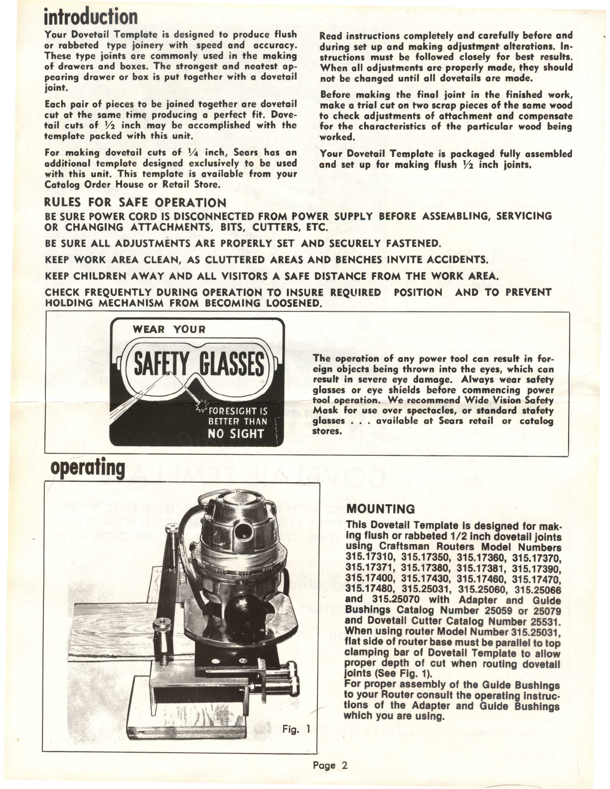
Place Router with base resting flat
on
dovetail
tem-
plate
so
that the guide bushing engages along the
edge of board (A). Make
a
straight
cut
from right
to
left
across
board (A, See Fig. 9). This is done
to
pre-
vent chipping the wood when the Router is moved in
and
out
of the fingers of the dovetail template.
Cut the dovetail joint, feeding the Router from left
to
right until the completed edge is accomplished. Before
removing the Router from the dovetail template,
recut
the dovetail, moving the Router from right
to
left
to
correct
any imperfections.
When the dovetail joint is completed wait until
cutter
bit has stopped completely before removing the Rout-
er
from the dovetail template. This precaution will
prevent damage
to
the template. When removing the
Router,
it
should
not
be lifted but should be moved
toward the operator until clear. Loosen template
clamp knobs and
remove
dovetail template. Without
removing board (A) loosen top clamp knobs (E),
re-
move
scrap piece and replace with piece that is
to
be
finished front board (B), flush with edge of board (A).
(Fig.
I2
Tighten top clamp knobs (E) firmly. After board (B) is
properly positioned, loosen front clamp knobs (I) and
remove
board (A). Attach dovetail template (F)
to
the
dovetail base with spacers (G) located outside brackets
(See Fig. 12). Holding template flat
on
boards with
one
hand, tighten template knobs (H) securely. Cut”
dovetail joint in board (B)
as
a
single piece. Loosen
all clamp
screws
and
remove
routed» sections.
Insert board (C) between front clamping bar and front
surface of dovetail base with bottom edge toward right
stop
screw.
Temporarily clamp board (C) "inside-out"
to
the right front of the fixture
so
that
it
extends
above the base. This is done
to
assist in properly posi-
tioning of board (B).
Insert board (B) between top clamping bar and ‘top
surface of dovetail base with bottom edge against
right stop
screw
and flush with extended portion of
board (C). Tighten top clamp knobs
to
hold board (B)
securely. Attach dovetail template
to
the dovetail base
with spacers located inside brackets. Holding template
flat
on
boards with
one
hand, tighten template clamp
knobs securely. Relocate board (C)
so
that
it
is flush
with the top of board (B) and against stop
screw
in
right front of dovetail base. Tighten front clamp knobs
to
hold board (C) securely. Loosen top clamp knobs
and
remove
board (B) from'the base and replace with
a
piece of scrap lumber of the
some
wood. This pro-
vides support in
area
of
cut
in board (C) which pre-
vents splintering
as
the
cutter
bit
moves
through cut.
Cut dovetail joint
as
described above.
Loosen all clamp
screws
and
remove
routed sections.
Dovetail
cuts
in board (D) and boards (A and C) may
be accomplished by following instructions
as
described
under "FLUSH FRONT DRAWER OR BOX."
MAKING ADJUSTMENTS
IF THE JOINT IS TOO TIGHT, raise the
cutter
bit very
slightly
to
make the
cut
more
shallow. (Follow depth
adjustment instructions
as
described in Router Own-
ers
Manual.)
IF THE JOINT IS TOO LOOSE, lower the
cutter
bit
very slightly
to
make the
cut
deeper.
IF THE FIT IS TOO DEEP,
turn
lock
nut
(J, See Fig. 3)
in
a
counter-clockwise direction until desired depth is
reached. (Adjust lock
nuts
equally and carefully).
IF THE FIT IS TOO SHALLOW,
turn
lock
nut
(J, See
Fig. 8) in
a
clockwise direction until desired depth is
reached.
WHEN ALL ADJUSTMENTS ARE PROPERLY MADE,
THEY SHOULD NOT BE CHANGED UNTIL ALL
DOVETAILS ARE CUT.
ROUT DOVETAIL FROM THE FRONT ONLY
—
DO
NOT RAISE OR LOWER ROUTER OR CUTTER BIT
WHILE BIT IS BETWEEN DOVETAIL TEMPLATE
FINGERS. KEEP ROUTER BASE FLAT AGAINST
TEMPLATE.
I
Page 6