Seating Matters Milano User manual

Instruction Manual
MilanoTM

This Instruction Manual is frequently updated to ensure safe use of your chair.
Visit seatingmatters.com where you can nd a free copy of the most up to date version.

1
Contents
2Technical Specication
5Operating Instructions
5Seat Cushion
6Tilt in Space (Manual Option)
7Back Angle Adjustment (Manual Option)
8Seat Depth Adjustment
9Seat Width Adjustment
10 Leg Elevation (Manual Option)
11 Negative Angle Leg Rest (Manual Option)
12 Footplate Height
13 Footplate Angle
14 Back Height Adjustment
15 Anterior & Posterior Tilt
16 Chair Movement
18 Chair Function (Motorised Option)
19 Charging Your Chair
20 Cleaning Instructions
21 Safety Instructions
22 Maintenance & Servicing
23 Recycling Policy
24 Warranty
25 Intellectual Property

2
MilanoTM
Technical
Specication

3
A
B
C
EF
G
H
L
D
I
Basic Dimensions
AOverall Height
BBack Height
CSeat Height
DOverall Length
1300mm / 51"*
770mm / 30"
540mm / 21"*
930mm / 36.5"
*Height measurements are based on 100mm castors.
Footplate Height Adjustments (From seat)
EHigh
FLow
400mm / 16"
580mm / 23"
Seat Depth (L)
Seat Position 1
Seat Position 2
Seat Position 3
400mm / 16"
450mm / 18"
500mm / 20"
Available Seat and Overall Width
G
400mm / 16"
450mm / 18"
500mm / 20"
H
700mm / 27.5"
750mm / 29.5"
800mm / 31.5"
Clearance Height
I 130mm / 5"*
*Height measurement is based on 100mm castors.
Arm Height
J 750mm
*Height measurement is based on 100mm castors.
Recline and Tilt Angles
ii (Back Angle Recline)
Manual
100° - 140°
40° range
Motorised
100° - 120°
20° range
iii (Leg Rest Angle)
Position 1 90° - 160°
Position 2 (Neg Angle) 75° - 145°
iv (Tilt in Space)
From 5° forward (anterior) tilt
to 35° backward (posterior) tilt
Chair weight unloaded
8 Stone / 52 Kg / 114lb
Patient weight limit
25 Stone / 159 Kg / 364lb
ii
iii
iv
J

4
Terminologies
Patient
The person sitting in the chair.
User
Competent person with responsibility for the persons sitting in the chair as well as the
suitability of the equipment for the Patient. The User is responsible for checking the chair
for faults during the course of its use.
All instructions must be read and understood before the chair may be used.

5
Seat Cushion
Removal and tting of the modular
Seating Matters cushion (g.1).
The underside of the Seating Matters
cushion is upholstered with non-slip
material, which creates a friction contact
when the chair is occupied. To t the
cushion correctly, place the cushion onto
the seat base of the chair, with the non-slip
underside of the cushion facing downwards
(g.1a). The rear, zipped end of the cushion
should be facing towards the back of
the chair (g.1b). See cushion label for
orientation. To remove the cushion, simply
lift it out from the chair.
(g.1)
(g.1a) (g.1b)
Back
Side
Internal
Front
Operating
Instructions
Correct tment of the Seating Matters cushion is important as the structure of the foam
allows good immersion ONLY when tted as instructed above.
6
For motorised option, see page 18.
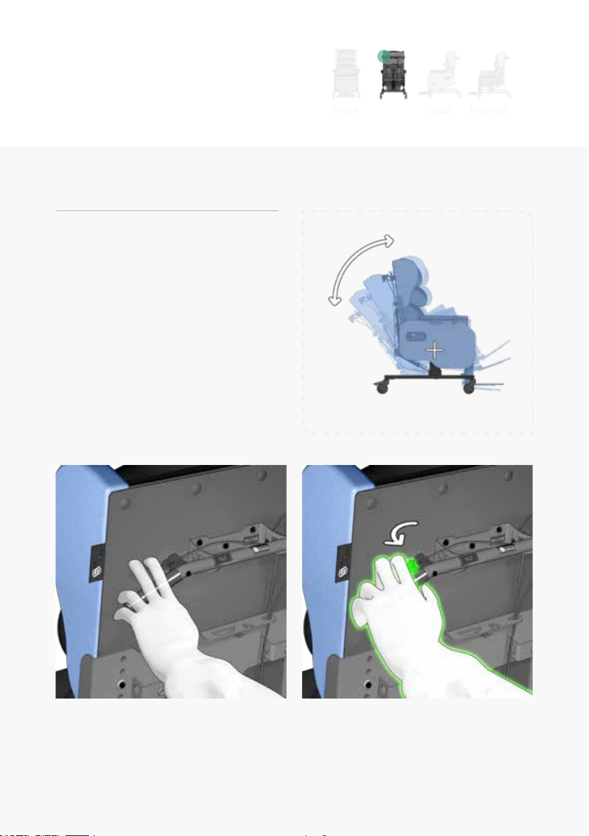
To adjust the tilt angle of the chair (g.2).
From the back of the chair, place both
hands on the push handle and locate the
left release lever (g.2a) with your
left hand. To tilt the chair, close your left
hand pulling the lever towards you (g.2b).
With the lever engaged, tilt the chair to the
required angle and release the lever again
to lock the tilt in this position.
Back
Side
Internal
Front
Tilt in Space (Manual Option)
(g.2)
(g.2a) (g.2b)

7
For motorised option, see page 18.
To adjust the back recline of the
chair (g.3).
From the back of the chair, place both
hands on the push handle and locate the
right release lever with your right
hand (g.3a). To recline the back of the
chair, push the lever with your right hand
(g.3b), with the lever engaged, recline the
back to the required angle and release the
lever again to lock the back in this position.
Back Angle Adjustment (Manual Option)
(g.3)
(g.3a) (g.3b)
Back
Side
Internal
Front

8
To adjust the seat depth of the chair (g.4).
*Some tools are required to carry out
this adjustment.
Using a 17mm spanner, remove the locking
nut and the safety washer (g4a). Do this
on both sides of the chair. Then move the
back to the desired position by sliding it
backward or forward through the arched
slots. (g.4b) Engage the safety washer and
tighten the locking nut securely.
Seat Depth Adjustment
*There are three options for seat depth.
16" 18" 20"
(g.4)
(g.4a) (g.4b)
X
L
l
17mm
Back Side
Internal
Front

9
Seat Width Adjustment
To increase or decrease the seat width of
the chair (g.5).
Loosen the two grips knobs on the
underside of the arm pads (g.5a). Move
the arm pads inwards to reduce seat width
and outwards to increase it (g.5a). Tighten
the grip knobs once the desired width has
been achieved.
(g.5)
(g.5a) (g.5b)
Back
Side
Internal
Front

10
To adjust the angle of leg rest elevation
(g.6).
Locate the release lever on the left side of
the chair (g.6a). To elevate the leg rest,
engage the release lever by pulling it out
(g.6b). Move the leg rest to the required
position and allow the manual lever to
move to its relaxed position.
Leg Elevation (Manual Option)
(g.6)
(g.6a) (g.6b)
Back
Side
Internal
Front

11
The closed angle of the leg rest can be
adjusted inwardly to achieve a negative
angle (g.7).
To change the setting, loosen the bolt
holding the gas strut in place (g.7a).
Remove the bolts. Move the gas strut to the
desired setting, insert the bolt and tighten.
13mm (x 2)
Negative Angle Leg Rest (Manual Option)
(g.7)
(g.7a) (g.7b)
Back
Side
Internal
Front

12
Back
Side
Internal
Front
Footplate Height
To adjust the seat to footplate height of
the chair (g.8).
The footplate can be adjusted in height
by pulling out the spring plunger, located
behind the calf pad of the chair.
Once the spring plunger is released it will
catch on the next immediate hole position.
The footplate can also be completely
removed by rstly elevating the leg rest and
secondly pulling the plunger and sliding the
footplate out of its guide bracket.
(g.8)
(g.8a) (g.8b)

13
Back
Side
Internal
Front
Footplate Angle
To adjust the angle of the footplate (g.9).
Using a 4mm allen key and 10mm spanner,
loosen and remove the xing bolt at either
side of the footplate pivot (g.9a).
Relocate both bolts to the required setting
(g.9b) and tighten securely.
10mm 4mm
(g.9)
(g.9a) (g.9b)

14
(g.10)
To adjust the back height of the
chair (g.10).
Remove the safety bolt positioned on the
left side of the back (g.10a). Loosen the
three sliding bolts (g.10b).
Slide the back to the desired height,
securing the safety bolt in place (g.10c)
and tightening the sliding bolts (g.10d).
(g.10a) (g.10b)
(g.10c) (g.10d)
Back Height Adjustment

15
Anterior & Posterior Tilt
To adjust the Anterior and Posterior tilt
of the chair (g.11).
To achieve Anterior or Posterior tilt the
gas strut must be positioned accordingly.
Manual Tilt (g.11a).
(i) To achieve Anterior tilt.
(ii) To achieve Posterior tilt.
Motorised Tilt (g.11b).
(i) To achieve Anterior tilt.
(ii) To achieve Posterior tilt.
ANTERIOR POSTERIOR
POSTERIOR
ANTERIOR
Motorised Tilt
Manual Tilt
(i) (ii)
(i) (ii)
(g.11a)
(g.11b)

16
Chair Movement
Directional Lock Castor
For control of direction and
manoeuvrability while pushing the chair
(g.13c).
The directional lock castor is located on the
front left side of the chair (g.13).
To engage the directional lock castor
simply press the green pedal with your foot
(g.13a) and swivel the castor until it clicks
into the forward line (g.13b).
(g.13a) Directional lock disengaged. (g.13b) Directional lock engaged.
(g.13c) Image showing use of the directional lock to improve manoeuvrability.
(g.13)

17
(g.14a) All locks disengaged. (g.14b) Braking castors engaged.
(g.14c) Image showing chair in locked position.
(g.14)
Braking Castors
To lock the chair in position (g.14c).
Both rear castors on the chair are total lock
castors (g.14). When engaged, the swivel
and rotation of the castor will be locked.
To engage the braking castor simply press
the pedal with your foot until it clicks in
place (g.14b).
18
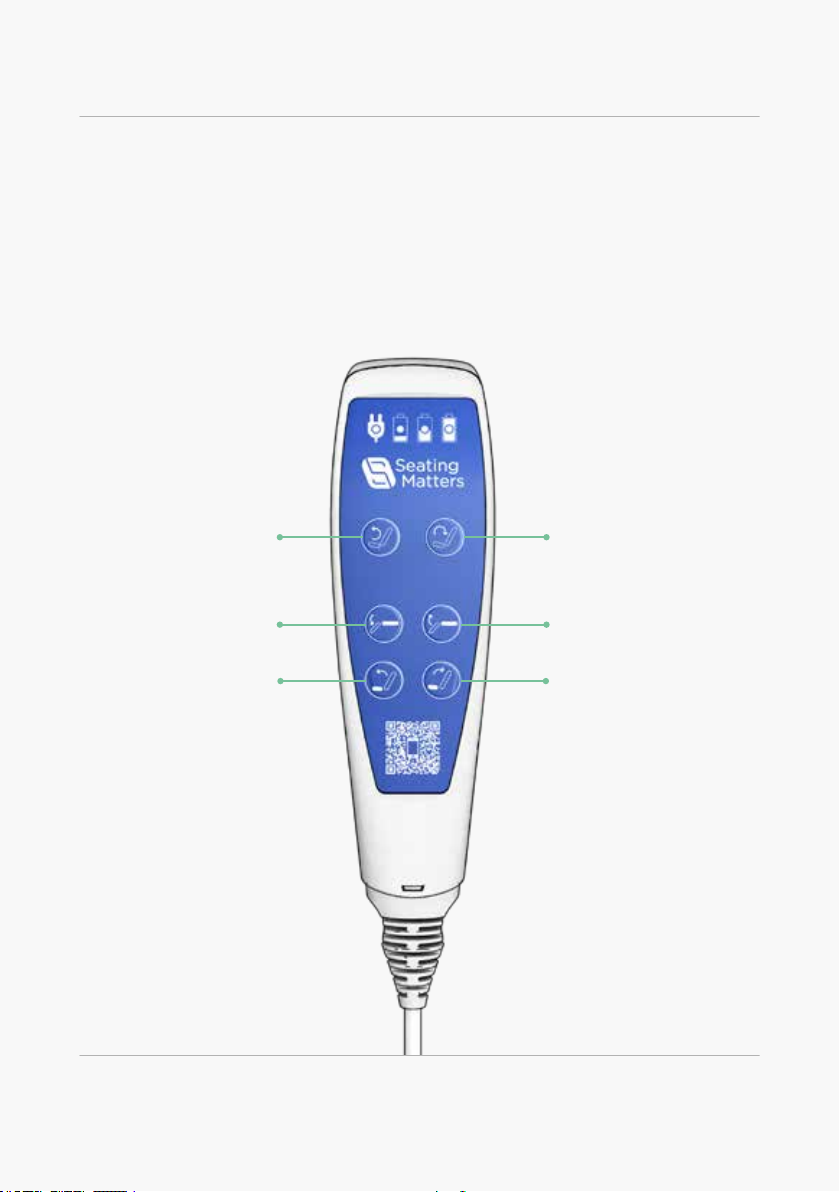
Motorised Handset
If your chair is a motorised model, Tilt in Space, Back Angle and Leg Elevation
are controlled by the handset.
Simply push the button displaying the symbol of your intended function.
Tilt Up Tilt Down
Back Rest DownBack Rest Up
Chair Function (Motorised Option)
Leg Rest UpLeg Rest Down
Other manuals for Milano
2
Table of contents
Other Seating Matters Medical Equipment manuals

Popular Medical Equipment manuals by other brands


Getinge
Getinge Arjohuntleigh Nimbus 3 Professional Instructions for use

Mettler Electronics
Mettler Electronics Sonicator 730 Maintenance manual

Pressalit Care
Pressalit Care R1100 Mounting instruction

Denas MS
Denas MS DENAS-T operating manual

bort medical
bort medical ActiveColor quick guide

AccuVein
AccuVein AV400 user manual


