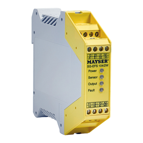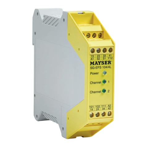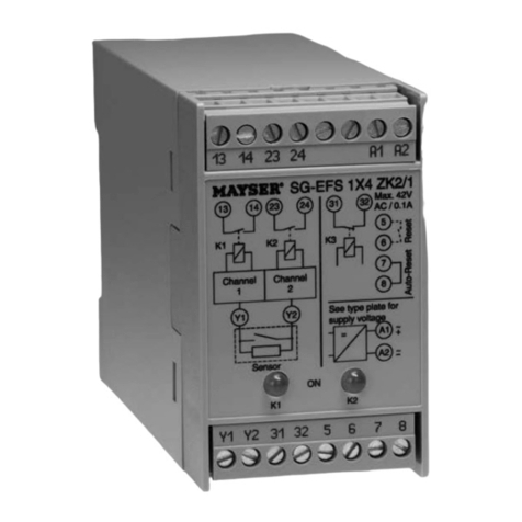
Safety Control Unit SG-EFS 1X4 ZK2/1 L20ms
Technical Data
Connecting voltage US
SG-EFS 104 ZK2/1 L20ms AC 24 V DC 24 V
SG-EFS 134 ZK2/1 L20ms AC 230 V
Voltage tolerance -15% to +10% -15% to +20%
Nominal frequency 50 Hz
Frequency tolerance 48 - 62 Hz
Power consumption < 5 VA for AC < 5 W for DC 28 V
Sensor voltage DC 15 V
Control Unit Outputs
Switching channel K1 and K2 11/14, 21/24
Switching voltage max. AC 240 V max. DC 24 V
Switching current 4 A 1 A
Fault indicator relay K3 31/32
Switching voltage max. AC 42 V max. DC 42 V
Switching current max.100 mA max. 100 mA
Permissible ambient temp. -20 °C to +50 °C
IMPORTANT NOTES! Please read!
To ensure correct and safe operation
of the unit, it must be properly trans-
ported and stored, properly installed
and commissioned, and operated in
accordance with its purpose.
Only persons familiar with the instal-
lation, commissioning and operation,
and with the corresponding qualicati-
ons to prove their skills, may work on
the units. They must observe the con-
tents of these instructions, the notes
given on the type plate of the unit and
the safety requirements relevant to the
installation and operation of electrical
systems.
This unit is constructed and tested to
prEN 1760 and DIN V 31006 and left our
factory in perfect condition with regard
to safety. In order to maintain this state,
you must observe the safety regulations
marked "WARNING!" in these operating
instructions. Failure to observe the sa-
fety regulations can lead to death, injury
to personnel, or damage to the unit and
other systems and equipment.
Should the information given in these
operating instructions be inadequate
in any way, please contact your local
technical centre, subsidiary or represen-
tative.
When using the device outside the
European Union, you must observe
the relevant regulations valid for the
country of use.
Note:
When switching inductive loads the
user must be tted out with spark ab-
sorbers.
2 connection variants:
- SG-EFS 1X4 ZK2/1 L20ms
with automatic reset
Bridge 7, 8 must be in place
The unit becomes active again as
soon as the sensor is no longer
activated.
The fault indicator relay K3 works in
synchrony with the sa fety relays K1,
K2 and is available as a voltage free,
normally closed contact.
- SG-EFS 1X4 ZK2/1 L20ms
with manual reset
Bridge 7, 8 must be removed
After deactivation of the unit by the
sensor it must be re-activated by
means of an external reset button.
The fault indicator relay K3 works in
synchrony with the safety relays K1,
K2 and is available as a voltage free,
normally closed contact.
WARNING!
Not for safety circuit:
- The fault indicator contact across 31,
32 is solely for information purposes
and must not be connected into the
safety circuit.
Do not cross link control
units:
- Clamps 5, 6 as well as 7, 8 and Y1,
Y2 are not voltage free and thus
may not be cross linked with further
control units.


