manuals.online logo
Brands
  1. Home
  2. •
  3. Brands
  4. •
  5. Seav
  6. •
  7. Control Unit
  8. •
  9. Seav BeWeather User manual

Seav BeWeather User manual

BeWeather Electronic Control
Unit
An electronic control unit integrated into the Wind, Sun and
Rain Sensor compartment, for the automation of sun blinds
and rolling window shutters, with the possibility of radio control
operation for individual and/or centralised control.
- Mod. (BeWeather 306) 306 MHz
- Mod. (BeWeather 330) 330 MHz
- Mod. (BeWeather 418) 418 MHz
- Mod. BeWeather 433 433,92 MHz
- Mod. BeWeather 433 SET “Narrow Band” 433.92 MHz
- Mod. BeWeather 868 “Narrow Band” 868.3 MHz
( ) Product intended for those countries where its use is
permitted.
TECHNICAL ATA
- Power supply 230V~ 50/60Hz 600W Max.
- Motor output 230V~ 500W Max.
- Operating temperature -10÷55°C
- Radio receiver see model
- Compatible radio controls 12-18 Bit or Rolling Code
- Anemometer sensitivity 5 ÷ 40 Km/h
- Sun sensor sensitivity 5 ÷ 40 Klux
- Number of codes that may be stored 10 Max.
- Packaging dimensions 240 x 185 x 110
mm.
- Container PC UL94V-0 (IP54)
CONNECTION OF CN 1 TERMINAL BOAR
1 Earth.
2 230 V line input (Phase).
3 230 V line input (Neutral).
4 Upward movement motor output.
5 Shared motor output.
6 Downward movement motor output.
INITIAL OPERATING CON ITION
The device can only operate in conjunction with one or more
radio controls. There is no radio control code stored in the
default factory setting.
OPERATION USING IFFERENT MO ELS OF RA IO CONTROL
Different models of radio control may be programmed. By
storing a code (1 button) a cyclic step-by-step operation (Up-
Stop-Down) may be achieved, and by storing two different
codes (2 buttons) different commands are produced, one for
Up and one for Down. Storing three different codes (3 “BeFree”
series buttons) produces three different commands the first for
Up, the second for Stop and the third for Down.
Operation using a 1-button radio control:
The following type of operation is obtained using a radio
control with a single button the first press controls the upward
movement of the shutter until the motor timer stops. The
second press controls the downward movement of the shutter.
If the button is pressed before the motor stops running, the
control unit will stop the shutter moving and the button will
need to be pressed again to reactivate the motor in the
opposite direction.
Operation using a 2-button radio control:
By using a radio control with 2 buttons, the following processes
may be carried out the first button (“Up”) controls the upward
movement, until the motor has stopped running, and the
second button (“Down”) controls the downward movement of
the shutter. If the upward movement is interrupted with another
“Up” command, the motor will continue to run in the upward
movement direction. If, however, the movement is interrupted
with a “Down” command, the control unit will stop the motor.
The procedure remains the same for the downward
movement phase.
Operation using a 3-button radio control (BeFree x1):
The following type of operation is obtained using the BeFree x1
radio control the (Up) button controls the upward movement
until the end of the motor time, the (Stop) button causes all
movement to stop and the (Down) button controls the
downward movement. If a stop command is sent during the
upward or downward movement, the control unit causes this
movement to stop. If a command that is in the opposite
direction to the current movement is sent during the upward or
downward movement, the control unit causes the shutter to
change direction.
Operation using a 3-button radio control (BeFree x3 - X6):
When using the BeFree x3 - x6 radio control, you will obtain
the same operation as previously described for the BeFree x1
version; in addition, by using the keys (-) and (+) at the sides of
the radio control it is possible to select the UP – STOP –
DOWN controls for 3 different types of use (BeFree x3) or for 6
different types of use (BeFree x6). In addition, by using the
keys (-) and (+) at the sides of the radio control it is possible to
enable and disable the sun sensor (the selection is confirmed
by a quick UP / Down movement of the motor).
INVERSION OF THE ROTATION MOTOR
If you notice that when pressing the UP key on the radio-
control the control unit causes the shutter to move upwards
instead of downwards, simply repeat the programming
procedure pressing the DOWN key instead of the UP key, or
invert the motor’s Upward movement wire and the Downward
movement wire.
GROUP OR GENERAL CENTRALISATION
It is also possible to enter two identical codes ( buttons ) from
one radio control onto all the control units or a group of them
which are situated at a maximum distance of 20 metres from
the point of command, in order to obtain general or partial
motion of more than one automation.
ANEMOMETER OPERATION
The electronic control unit will cause the sun shade to move
upwards every time the wind exceeds the selected threshold.
SUN SENSOR OPERATION
The electronic control unit controls the downward movement of
the sun shade after 5 minutes during which the brightness is
greater than the threshold selected using the VR1 trimmer and
displayed when the SUN LED lights up; it also controls the
upward movement of the shade after 5 minutes during which
the brightness is below the selected threshold.
Sun sensitivit adjustment ( 5 ÷ 40 Klux )
The control unit allows you to adjust the sensitivity of the Sun
Sensor using the VR1 trimmer. When the SUN LED lights up
on the control unit, this indicates that the intensity of the sun
exceeds the selected threshold; this enables you to use the
current light conditions as a reference when setting the desired
value.
RAIN SENSOR OPERATION
The electronic control unit will cause the sun shade to move
upwards as soon as the sensitive part of the rain sensor gets
wet with water as displayed when the RAIN LED lights up.
OPERATION PRINCIPLES
SW1 SW1 SW1 SW1
1 Rev. 1.2 31/01/08
GB
Step-by-step P/P + Aut Sensors User Present Sensor Test
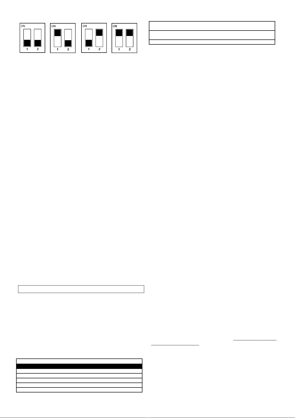
1) Step-by-step ( ip 1 and 2 OFF)
The electronic control unit has a cyclic "Step-by-Step" logic,
whose operation depends on the type of radio control
associated with it (see operation with radio control with 1-2-3
buttons).
2) Step-by-step + Aut. Sensors ( ip 1 ON and ip 2 OFF)
The electronic control unit allows the "Step-by-Step" operation
as described above, with the addition of the automatic control
of the Wind and Rain sensors. After the activation of one of the
two sensors, once the disturbance is over, the electronic
control unit controls the downward movement of the sun shade
after 5 minutes.
3) Manually-controlled ( ip 1 OFF and ip 2 ON)
Using the radio control the “User present” operating mode can
be obtained, i.e. the control must be constantly enabled so that
the blind or shutter can be moved as necessary. The
movement stops when the control is released.
4) Sensor Test ( ip 1 and 2 ON)
The electronic control unit allows to check the sensor operation
and the correct rotation direction upon installation; we advise
that you place the shade in intermediate position in order to
verify the confirmation movements during the tests.
Warning after you have tested the sensors, restore the Dip 1
and 2 in the desired operation mode.
Anemometer : manually turn the Anemometer blades; at the
same time, the control unit will cause an upward movement
lasting 5 seconds.
Sun sensor : turn the VR1 trimmer as far as possible in a
clockwise direction (in the + position); at the same time, the
control unit will cause the SUN LED to light up and there will be
a downward movement lasting 5 seconds. Turn the VR1
trimmer in an anticlockwise direction (in the – position); at the
same time, the control unit will cause the SUN LED to switch
off and there will be an upward movement lasting 5 seconds.
Rain sensor : get the sensitive part of the Rain Sensor wet; at
the same time, the control unit will cause the RAIN LED to light
up and there will be an upward movement lasting 5 seconds.
When you have completed the test, make sure you have dried
the sensitive part of the rain sensor before using the control
unit in the normal operation mode.
PROGRAMMING BUTTONS AN IN ICATOR LE S
SEL button: selects the type of function to store; selection is
indicated by the LED flashing. The desired function can be
selected by pressing the button repeatedly. The selected
function remains active for 15 seconds (flashing LED) following
which the control unit returns to its original status.
SET button: programmes the function that has been selected
using the SEL. Key.
Indicator LE s
LED on option stored.
LED off option not stored.
Flashing LED option selected.
---------------------- MAIN MENU -----------------
Reference LE LE Off LE On
1) CODE No code TX Pgm code
2) T. MOT. Motor time 2 minutes Pgm motor time
3) WIND SPEED Wind safety 25 km/h Pgm. Wind safety
4) SUN SENSOR Sun sensor = OFF Sun sensor = ON
5) RAIN SENSOR Rain sensor = OFF Rain sensor = ON
6) SUN Sun Presence = No Sun Presence =
Yes
7) RAIN Rain Presence = No Rain Presence =
Yes
8) R. HEAT R. Heat = No R. Heat = Yes
1) CO E ( Radio control programming )
Programming using a 1- or 2-button radio control:
To programme the transmission codes in the radio control,
proceed as follows press the SEL key; the CODE LED begins
to flash. Send the first preselected code using the relevant
radio control at the same time; when the CODE LED begins to
flash rapidly send the second code to be stored. The CODE
LED will remain lit and the programming will be complete. If the
second code is not sent within 10 seconds the control unit exits
the programming stage, selecting the function using a single
button on the radio control. If you have stored 10 codes and
you repeat the programming operation, all the indicator LEDs
will start flashing extremely rapidly to indicate that no more
codes can be stored.
Programming using a 3 button radio control from the
“BeFree" series.
The control unit allows you to store the whole “BeFree” radio-
control by programming only the UP button.
To programme the “BeFree” radio-control codes, follow this
procedure press the SEL key; the CODE LED begins to flash.
Press the UP key of the desired radio control at the same time;
at that moment, the CODE LED will remain lit and
programming will be complete. If all of the possible 10 radio
control codes have been stored and you repeat the
programming operation, all indicator LEDs will start flashing
very rapidly to indicate that no new codes can be stored.
Deleting the codes To delete all transmission codes
stored in the memory, proceed as follows press the SEL
button; the CODE LED starts flashing. Then press the SET
button; the CODE LED switches off and the procedure is
complete.
2) T. MOT. ( Motor Timer Programming )
The control unit comes with a motor power supply time of two
minutes (T. MOT. LED OFF).
The motor time must be programmed when the shutter is down
and in the following way
Press the SEL key until the T. MOT LED key flashes, then hold
down the SET key; the shutter will begin to move upwards.
Once the desired position has been reached, release the SET
key – at this very moment, the motor time will be stored and
the T. MOT LED will remain lit.
If you are using an automation which has a stop limit, we
recommend that you set a time which exceeds the stop limit of
the shutter by a few seconds.
If you want unlimited motor time, perform the same
programming procedure, holding down the SET key for less
than two seconds; the T. MOT LED will remain lit and the
unlimited time function will be set. The operation may be
repeated if a mistake is made during programming.
3) WIN ( Wind Safety Threshold Programming )
Displa ing the programmed wind threshold
The wind safety threshold may be displayed in the following
way use the SEL key to navigate to the WIND LED position;
the LED will double-flash the same number of times as the
stored wind safety threshold (each WIND LED double-flash
corresponds to an increase of 5 km/h), (for example 5 WIND
LED flashes = 25 km/h).
Wind safety threshold selection from 5 to 40 km/h
The control unit comes with a default wind safety threshold
setting of 25 km/h (WIND LED OFF).
The wind safety threshold may be programmed in the following
way use the SEL key to navigate to WIND LED, then press the
SET key to start the programming procedure At the same time
the WIND LED will begin to double-flash (each double-flash of
the WIND LED corresponds to an increase of 5 km/h); press
2 Rev. 1.2 31/01/08
the SET key once the desired threshold has been reached – at
this moment, the selected value will be stored and the WIND
LED will remain lit (for example: 5 WIND LED double-flashes =
25 km/h).
The operation may be repeated if a mistake is made during
programming.
4) SUN SENSOR ( Sun Sensor ON/OFF )
Enabling the Sun Sensor
The control unit comes with the Sun Sensor disabled (SUN
SENSOR LED OFF).
The Sun Sensor may be enabled in the following way press
the SEL key until the SUN SENSOR LED flashes, then press
the SET key briefly; at this moment the SUN SENSOR LED
remains lit and the Sun Sensor will be enabled. Repeat the
operation to disable the Sun Sensor.
Enabling the Sun Sensor using a 3-button radio control
(BeFree x3 - X6):
The Sun Sensor may be enabled in the following way hold
down the (+) key on the radio control that was programmed
previously for 5 seconds; at the same time the control unit will
cause the shutter to move Up/Down for 1 second to confirm
that the Sun Sensor has been enabled, and the SUN SENSOR
LED will remain lit. Repeat the operation to disable the Sun
Sensor by following the same procedure, but instead holding
down the (-) key for 5 seconds.
5) RAIN SENSOR ( Rain Sensor ON/OFF )
Disabling the Rain Sensor
The control unit comes with the Rain Sensor enabled (RAIN
SENSOR LED ON).
The Rain Sensor may be disabled in the following way press
the SEL key until the RAIN SENSOR LED flashes, then press
the SET key briefly; at this moment the RAIN SENSOR LED
switches off and the Rain Sensor will be disabled. You can
repeat the operation to enable the Rain Sensor.
EXTEN E MENU
The control unit is supplied by the manufacturer with the option
of selecting only the functions listed in the main menu.
To enable the functions of the extended menu proceed as
follows press the SET key and hold for 5 seconds; the SUN,
RAIN and R. HEAT LEDs will flash and the user has 30
seconds within which to select the functions of the extended
menu using the SEL and SET keys. After another 30 seconds
the control unit returns to the main menu.
---------------------- EXTEN E MENU -----------------
Reference LE LE Off LE On
A) CODE remote PGM = OFF remote PGM = ON
B) T. MOT. Aut. movement lock = OFF Aut. movement lock =
ON
C) WIND SPEED Safety upward = OFF Safety upward =
ON
D) SUN SENSOR RAIN inversion = OFF RAIN inversion =
ON
E) RAIN SENSOR Aut. movements 5 min. Aut. Movements 10
min.
C) SUN Flashing beacon ON/OFF
C) RAIN Flashing beacon ON/OFF
G) R. HEAT Flashing beacon ON/OFF
A) CO E
(Remote programming of radio control):
The control unit allows the transmission code to be
programmed by remote, without using the SEL key.
To programme the transmission code remotely, proceed as
follows send the radio control code continuously for more than
10 seconds and the control unit will enter the programming
mode as described above for the CODE LED in the main
menu.
The control unit is supplied by the manufacturer with remote
programming of the transmission code not enabled; to enable
the function proceed as follows check that the extended menu
is enabled (SUN, RAIN and R. HEAT LEDs flash), using the
“SEL” key navigate to CODE LED when flashing and press the
“SET” key the CODE LED lights up permanently and
programming is completed. Repeat the operation to restore the
previous configuration.
B) T. MOT. (Automatic movement lock):
The control unit enables the prevention of Automatic
movements (Up / Down sun blind movements on the Sun
Sensor command or Automatic Sensors function), so that if a
Stop command is sent from a radio control during the
movement, the control unit momentarily locks the Automatic
movements until a new Up or Down command is sent. The
control unit is supplied by the manufacturer with the Automatic
Movement Lock disabled; to enable the function proceed as
follows check that the extended menu is enabled (SUN, RAIN
and R. HEAT LEDs flash), using the “SEL” key navigate to T.
MOT. LED when flashing and press the “SET” key the T.
MOT. LED lights up permanently and programming is
completed. Repeat the operation to restore the previous
configuration.
C) WIN ( Safety Upward Movement ) :
The control unit is supplied by the manufacturer with the Safety
upward movement function disabled; if you wish to enable the
function, in such a way that after 12 hours of inactivity of the
Wind Sensor the control unit automatically control the safety
upward movement, proceed as follows check that the
extended menu is enabled (SUN, RAIN and R. HEAT LEDs
flash), using the “SEL” key navigate to WIND LED when
flashing and press the “SET” key the WIND LED lights up
permanently and programming is completed. Repeat the
operation to restore the previous configuration.
) SUN SENSOR ( Rain control movement inversion ) :
The control unit is supplied by the manufacturer with the Rain
Control = Upward Movement Control association, that is to say
when the rain sensor detects the rain, the control unit controls
the upward movement. If you wish that the control unit controls
the downward movement when rain is detected by the rain
sensor, proceed as follows check that the extended menu is
enabled (SUN, RAIN and R. HEAT LEDs flash), using the
“SEL” key navigate to SUN SENSOR LED when flashing and
press the “SET” key the SUN SENSOR LED lights up
permanently and programming is completed. Repeat the
operation to restore the previous configuration.
E) RAIN SENSOR (Automatic sensor action Time) :
The control unit is supplied by the manufacturer with the
Automatic sensor action Time of 4 minutes; if you wish to set
10 minutes to reduce the motor movements, proceed as
follows check that the extended menu is enabled (SUN, RAIN
and R. HEAT LEDs flash), using the “SEL” key navigate to
RAIN SENSOR LED when flashing and press the “SET” key
the RAIN SENSOR LED lights up permanently and
programming is completed. Repeat the operation to restore the
previous configuration.
RESET
To reset the default configuration of the control unit, press the
SEL and SET buttons simultaneously; all indicator LEDs will
switch on and then off again immediately.
3 Rev. 1.2 31/01/08
FOR THE USER - IMPORTANT
- The device should not be used by children or by individuals
with reduced physical or psychological abilities unless
supervision is provided or instruction given on how to operate
it.
- Do no le children play wi h he device; keep radio con rols
ou of heir reach.
- CAUTION: Keep his ins ruc ion manual in a safe place and
adhere o he impor an safe y ins ruc ions con ained wi hin i .
Non-adherence o hese ins ruc ions may lead o proper y
damage and serious acciden s.
- Examine he sys em frequen ly o check for any signs of
damage. Do no use he device if i needs o be repaired.
Warning
All opera ions which require he casing o be opened (such as
wire connec ion, programming, e c.) mus be carried ou during
ins alla ion, by skilled s aff only. For any o her procedure which
requires he casing o be opened again (re-programming,
repairs or si e modifica ions), please con ac he echnical
assis ance service.
SEAV s.r.l. hereby declares that the below products
BeWeather Series
conform to the specifications in the Directives R&TTE
99/5/EC, EMC 2004/108/EC, LVD 2006/95/EC.
4 Rev. 1.2 31/01/08
FOR THE INSTALLER – IMPORTANT
- The BeWea her con rol uni mus be permanen ly connec ed
o he power supply ne work and is no equipped wi h any
ype of 230 V a/c elec ric line sec ioning device. The ins aller
is responsible for ins alling a sec ioning device in he sys em.
An omnipolar swi ch wi h overhea ing ca egory III mus be
ins alled. I mus be posi ioned in such a way ha i is
pro ec ed agains acciden al closures.
- For connec ions (power supply and ou le con ac ) we
recommend he use of flexible wires wi h an insula ing shea h
in harmonised polychloroprene (H05RN-F). The wires should
have a minimum cross-sec ion of 0.75 mm2.
- Fas en he connec ion cables using he cable clamp
supplied wi h he produc ki .
- Handle he con rol uni wi h care during he ins alla ion
process
and make sure ha all componen s are properly
assembled. Pay par icular a en ion o he ceramic pla e and
he fla connec ion cable. When closing he box again, i
mus fold back on i self normally.
- I is very impor an o es ablish an exac loca ion so ha he
produc is exposed o wea her condi ions i can con rol.
- Fix he device o he wall using he screws and rawlplugs
supplied wi h he produc , in he correc posi ion (see figure
below).
- Make sure ha he con rol uni remains il ed a
approxima ely 45 degrees (Fixing area a he op, round end
of he box a he bo om).
- Do no pain or varnish he sensi ive surface of he con rol
uni .
- The dir which accumula es on he surface of he rain
sensor res ric s i s sensi ivi y: we herefore recommend ha i
is cleaned once or wice a year using a damp clo h, af er he
elec rici y supply has been disconnec ed.
- Connec he ear h wire of he mo or o he ear h wire of he
elec rical sys em using he special erminal on he con rol uni ,
as illus ra ed in he connec ion diagram.
−For he radio receiver o opera e correc ly when wo or
more con rol uni s are used, we recommend ha you ins all
he devices a leas 3 me res away from each o her.

Other manuals for BeWeather

1

This manual suits for next models

6

Other Seav Control Unit manuals

Seav LR 2200/M User manual

Seav

Seav LR 2200/M User manual

Seav LR 2215 Series User manual

Seav

Seav LR 2215 Series User manual

Seav LRX 2299 NEW User manual

Seav

Seav LRX 2299 NEW User manual

Seav BeSUN 433 User manual

Seav

Seav BeSUN 433 User manual

Seav LG 2215TC User manual

Seav

Seav LG 2215TC User manual

Seav LRX 2218 User manual

Seav

Seav LRX 2218 User manual

Seav LRX 2186 User manual

Seav

Seav LRX 2186 User manual

Seav LG 2060 New Reader User manual

Seav

Seav LG 2060 New Reader User manual

Seav LRS 2197 User manual

Seav

Seav LRS 2197 User manual

Seav LXB 2102 NEW User manual

Seav

Seav LXB 2102 NEW User manual

Seav LRX 2239 NEW 12V User manual

Seav

Seav LRX 2239 NEW 12V User manual

Seav LRX 2247 User manual

Seav

Seav LRX 2247 User manual

Seav LG 2218 User manual

Seav

Seav LG 2218 User manual

Seav LRX 2137 NEW User manual

Seav

Seav LRX 2137 NEW User manual

Seav LRX 2205 User manual

Seav

Seav LRX 2205 User manual

Seav LG 2020 New User manual

Seav

Seav LG 2020 New User manual

Seav LXB 2035 User manual

Seav

Seav LXB 2035 User manual

Seav LRX 2329 User manual

Seav

Seav LRX 2329 User manual

Seav LG 2205 User manual

Seav

Seav LG 2205 User manual

Seav BeSUN 433 User manual

Seav

Seav BeSUN 433 User manual

Popular Control Unit manuals by other brands

GF V82 instruction manual

GF

GF V82 instruction manual

Agilent Technologies 81570A user guide

Agilent Technologies

Agilent Technologies 81570A user guide

Fancom MRK.1 manual

Fancom

Fancom MRK.1 manual

Honeywell S7800A Installation

Honeywell

Honeywell S7800A Installation

Cabletron Systems MCC-FRIO quick reference

Cabletron Systems

Cabletron Systems MCC-FRIO quick reference

Supermicro SUPERO C9Z590-CG Quick reference guide

Supermicro

Supermicro SUPERO C9Z590-CG Quick reference guide

ASTUS QC25 Hardware user's guide

ASTUS

ASTUS QC25 Hardware user's guide

ITI 60-620 installation instructions

ITI

ITI 60-620 installation instructions

Rain Bird HV Series installation instructions

Rain Bird

Rain Bird HV Series installation instructions

Comtech EF Data Vipersat CDD-562L Installation and operation manual

Comtech EF Data

Comtech EF Data Vipersat CDD-562L Installation and operation manual

Assa Abloy Securitron B100 quick start guide

Assa Abloy

Assa Abloy Securitron B100 quick start guide

Velleman VMA214 user manual

Velleman

Velleman VMA214 user manual

VAT 612 GC Series Installation, operating,  & maintenance instructions

VAT

VAT 612 GC Series Installation, operating, & maintenance instructions

Danfoss AB-QM DN 125 installation guide

Danfoss

Danfoss AB-QM DN 125 installation guide

PRASTEL EASY-PAD instruction manual

PRASTEL

PRASTEL EASY-PAD instruction manual

Fanstel BT600I user manual

Fanstel

Fanstel BT600I user manual

CAME ZL38 installation manual

CAME

CAME ZL38 installation manual

NAPCO NP-DMOD-4OUT instructions

NAPCO

NAPCO NP-DMOD-4OUT instructions

manuals.online logo
manuals.online logoBrands
  • About & Mission
  • Contact us
  • Privacy Policy
  • Terms and Conditions

Copyright 2025 Manuals.Online. All Rights Reserved.