Seavo SV1a-25514P Series User manual
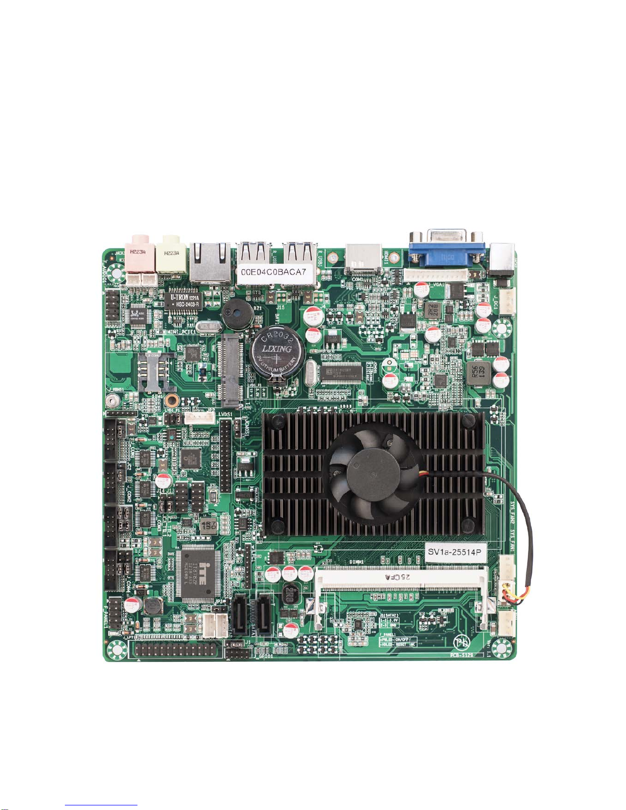
SV1a-25514P Series Motherboard
User Guide
Ver 1.1

- 1 -
深圳市信步科技有限公司 地址:深圳市福田区车公庙泰然工贸园 210 栋西座 5H T 86-755-88251900 F 86-755-88251910 www.seavo.com
Contents
1. Models and Attentions.........................................................................................................................2
1.1 Models...........................................................................................................................................2
1.2 Attentions ......................................................................................................................................2
2. Specification........................................................................................................................................3
3. Data Flow............................................................................................................................................4
4. Jumpers / Headers and Connectors...................................................................................................5
5. Definition of Jumpers / Headers and Connectors...............................................................................7
6. BIOS setup........................................................................................................................................14

- 2 -
深圳市信步科技有限公司 地址:深圳市福田区车公庙泰然工贸园 210 栋西座 5H T 86-755-88251900 F 86-755-88251910 www.seavo.com
1. Models and Attentions
1.1 Models
This manual is applied to following models:
1.2 Attentions
1) Notes under a table or figure indicate the difference of models, or alternative definition of
specific pin of the header (jumper/connector).
2) How to identify the first pin of a header or jumper
Usually, there is a thick line or a triangle near the header’s or jumper’s pin 1.
Square pad, which you can find on the back of the motherboard, is usually used for pin 1.
Model Chipset COM HDMI LAN Mini PCI-E DC12V IN
SV1a-25514P D2550+NM10 4 1 1 1 √
SV1a-25514P-B D2550+NM10 4 0 1 1 √
- 3 -
深圳市信步科技有限公司 地址:深圳市福田区车公庙泰然工贸园 210 栋西座 5H T 86-755-88251900 F 86-755-88251910 www.seavo.com
2. Specification
Model SV1a-25514P SV1a-25514P-B
CPU Intel○
RAtomTM D2550, Dual-core, clock speed 1.86G,TDP 10W
Chipset Intel○
RNM10,TDP 1.5 W
Display
1 * VGA
1 * Dual Channel 24-bit LVDS [1]
1 * HDMI
1 * VGA
1 * Dual Channel 24-bit LVDS [1]
Memory Support DDR3 1066/800 MHz, 1 * SO-DIMM slot,Up to 4GB
Storage 2 * SATA 3Gbps [3]
Ethernet 1 * Realtek 8111E PCI-E 1000Mbps LAN
Audio Realtek ALC662 5.1 Channel HDA Codec , Support MIC/Line-out Ports
1 * Amplifier
COM 3* RS232+1 * RS232 or TTL [2]
Other Ports
8 * USB2.0 :4 ( Rear I/O) + 4 ( Header) [4]
8 * GPIO
1 * LPT
1 * SIM Card Slot
1 * PS/2 Header
1 * Mini PCI-E(3G Devices are Supported) [3][4]
1 * F- Audio
Temperature Storage: -20~75℃
Operating: 0~60℃
BIOS AMI UEFI BIOS
Factor Mini-ITX
Notes:
[1]: The Dual Channel 24-bit LVDS supports a max resolution of 1920x1200, and a selectable Single
Channel 24-bit LVDS support a max resolution of 1440x900.
[2]: COM1 header and COM1 connector on the rear panel (if existed) can’t be used at the same time.
[3]: Mini PCI-E slot can be used to support mSATAdevices at the cost of invalidating SATA1.
[4]: Mini PCI-E slot can support 3G devices by setting jumpers, and then one of the front USB port will be
invalid(see page 6).

- 4 -
深圳市信步科技有限公司 地址:深圳市福田区车公庙泰然工贸园 210 栋西座 5H T 86-755-88251900 F 86-755-88251910 www.seavo.com
3. Data Flow
Intel Atom
D2550
Intel NM10
Express Chipset
Super I/O
DMI
PCI-E
LPC
SATA*1
USB*1
USB*4
Analog Display
HD Display
PCI-E*1
DDRIII
SO-DIMM
UIM
SATA
Port1
Mini PCI-E
SIM
USB 2.0
4 Ports
PS/2
KBMS
COM
4Ports
LPT
HDMI
VGA
SATA*1
SATA
Port2
Audio
CODEC
Line out
MIC
Amplifier
Realtek
8111E RJ45
Port
USB*4 USB 2.0
4Headers
DP
LVDS Single
24Bit(optional)
LVDS Dual
24Bit
- 5 -
深圳市信步科技有限公司 地址:深圳市福田区车公庙泰然工贸园 210 栋西座 5H T 86-755-88251900 F 86-755-88251910 www.seavo.com
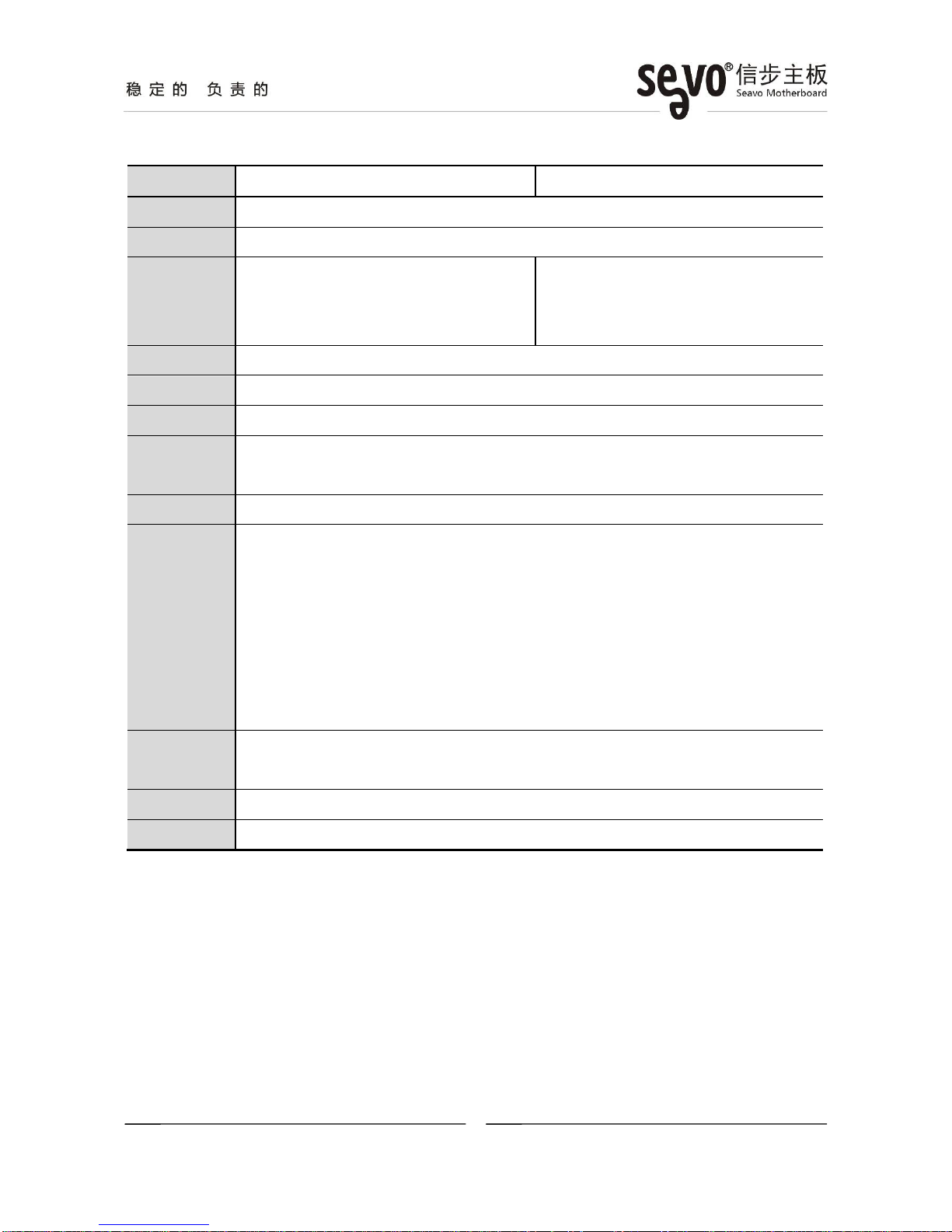
4. Jumpers / Headers and Connectors
Notes:
[1]: One of the USB port of F_USB1 header(4 pins on the left side) will be invalid, if 3G devices are
supported(see page 3).
[2]: TheDual Channel 24-bit LVDS support a max resolution of 1920x1200, and a selectable Single
Channel 24-bit LVDS support a max resolution of 1440x900.
[3]: Mini PCI-E slot can support 3G devices by setting jumpers, and then one of the front USB port will be
invalid.
[4]: Mini PCI-E can be used to support mSATA devices at the cost of invalidating SATA1.
[5]: COM1 header and COM1 connector on the rear panel (if existed) can’t be used at the same time.
- 6 -
深圳市信步科技有限公司 地址:深圳市福田区车公庙泰然工贸园 210 栋西座 5H T 86-755-88251900 F 86-755-88251910 www.seavo.com
Notes:
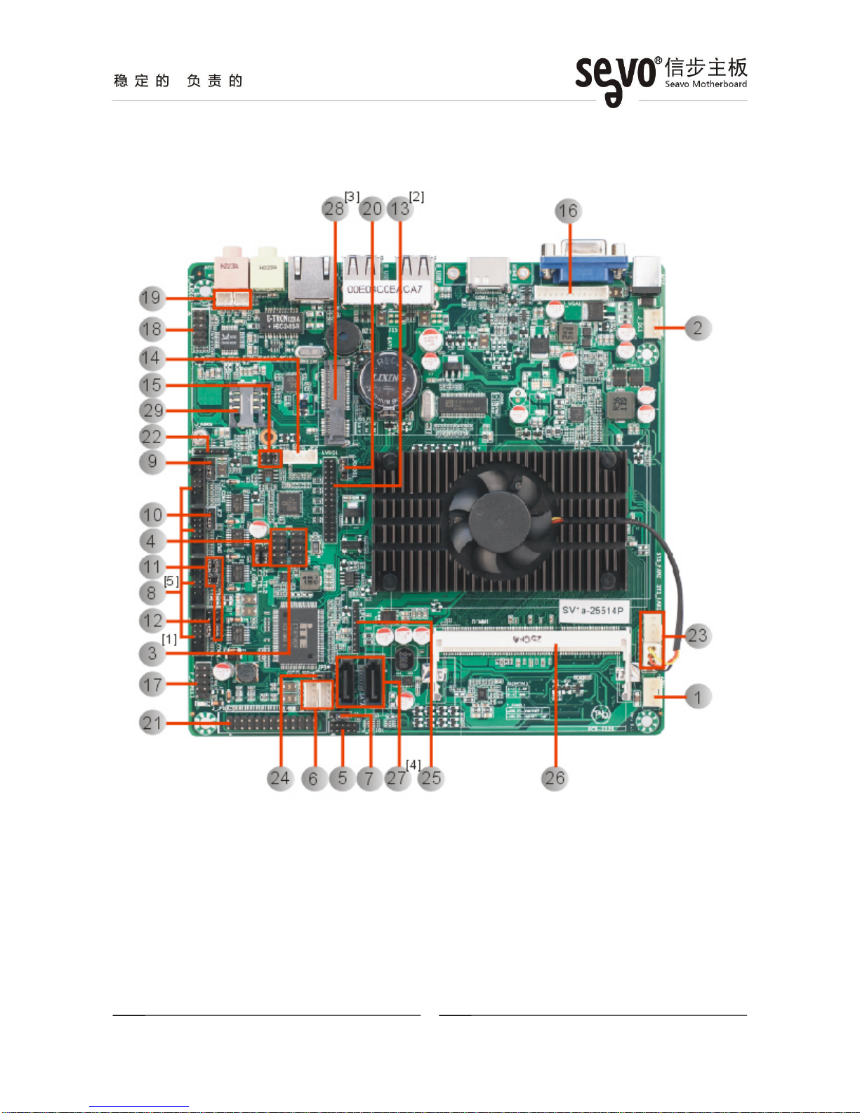
[1]: The HDMI connector co-lays with a COM connector (DB9).
Jumpers / Headers and Connectors
1 ATX Power Output Connector P719 Amplifier Headers P12
2 DC Power Supply Connector P720 CMOS Clear Jumper P13
3 Front USB Headers P721 LPT Header P13
4 F_USB1 Signal Control Jumper P722 Keyboard and Mouse Header P13
5 GPIO Header P823 System Fan Headers P13
6 SATA Power Supply Connectors P824 Power-on Signal Selection Jumper P14
7 SATA1 DOM Power Supply Selection
Jumper P825 Debug Header
8 COM1~4 Headers P9 26 SO-DIMM Slot
9 COM1 Control Jumper P927 SATA Connectors
10 COM2 Control Jumper P10 28 Mini PCI-E Slot
11 COM3 Control Jumpers P10 29 SIM Card Slot
12 COM4 Control Jumper P10 30 DC12V Power Supply Connector
13 LVDS Header P11 31 VGA Connector
14 LVDS Backlight Control Header P11 32 HDMI Connector
15 LVDS VCC Selection Jumper P11 33 USB Connector
16 VGA Header P12 34 LAN Connector
17 Front Panel Header P12 35 Audio Connectors
18 FrontAudio Header P12
- 7 -
深圳市信步科技有限公司 地址:深圳市福田区车公庙泰然工贸园 210 栋西座 5H T 86-755-88251900 F 86-755-88251910 www.seavo.com
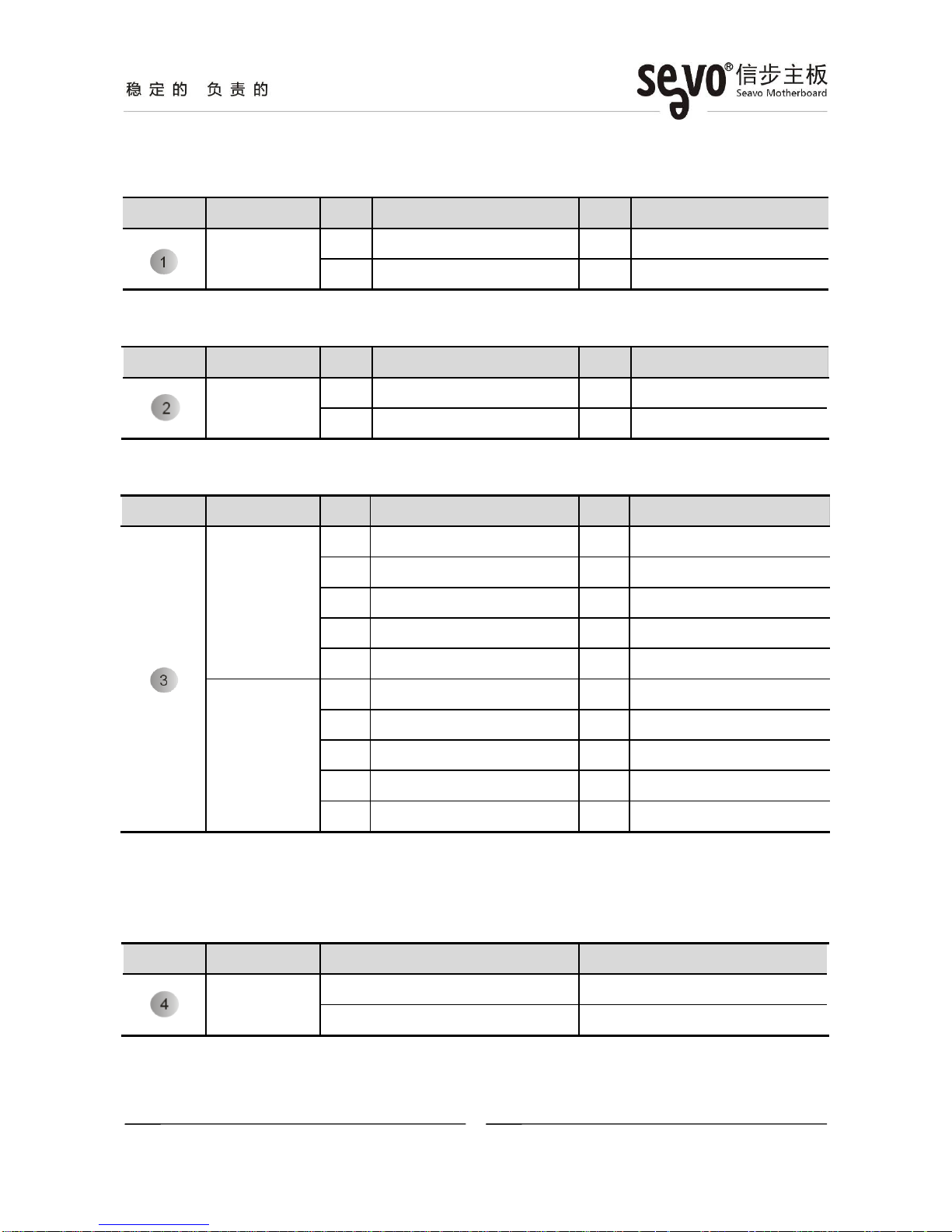
5. Definition of Jumpers / Headers and Connectors
[1] ATX Power Output Connector(4*1 Pin 2.54mm)
Location Connector Pin Definition Pin Definition
ATX1 1 +12V OUT 2 GND
3 GND 4 +5V OUT
[2] DC Power Supply Connector(4*1 Pin 2.54mm)
Location Connector Pin Definition Pin Definition
J_DC1 1 +12V IN 2 +12V IN
3 GND 4 GND
[3] Front USB Headers(5*2 Pin 2.54 mm)
Location Header Pin Definition Pin Definition
F_USB1
1 + 5 V 2 + 5 V
3 J13* 4 USBP7-
5 J14* 6 USBP7+
7 GND 8 GND
10 N/C
F_USB2
1 + 5 V 2 + 5 V
3 USBP4- 4 USBP5-
5 USBP4+ 6 USBP5+
7 GND 8 GND
10 N/C
*These signals are depend on relevant Jumpers (e.g. Pin3 of F_USB1 depends on J13 Jumper), to
find more details, check the following table (Location 4).
[4] F_USB1 Signal Control Jumpers(3*1 Pin 2.54 mm)
Location Jumper Settings Function
J13, J14 1-2 3G devices supported [1]
2-3(Default) F_USB1 Enable
Notes:
[1] When 3G devices are supported, one of the USB ports of F_USB1 will be invalid (see page 6).

- 8 -
深圳市信步科技有限公司 地址:深圳市福田区车公庙泰然工贸园 210 栋西座 5H T 86-755-88251900 F 86-755-88251910 www.seavo.com
[5] GPIO Header(5*2 Pin 2.00mm)
Location Header Pin Definition Pin Definition
J_GPIO1
1 GPO37(0xA02 Bit7) 2 GPI22(0x050E Bit6)
3 GPO51(0xA04 Bit1) 4 GPO38(0x538 Bit6)
5 GND 6 GPO7(0x50C Bit7)
7 GPI33(0x538 Bit1) 8 GPI36(0x538 Bit4)
9 GPO39(0x538 Bit7) 10 + 5V
[6] SATA Power Supply Connectors (4*1 Pin 2.00mm)
Location Connector Pin Definition Pin Definition
SATA_P1 1 + 12V 2 GND
3 GND 4 + 5V
SATA_P2 1 + 12V 2 GND
3 GND 4 + 5V
[7] SATA1 DOM Power Supply Selection Jumper (3*1 Pin 2.00mm)
Location Jumper Settings Function
J1 1-2 Pin 7: 5V
2-3(Default) Pin 7: GND
- 9 -
深圳市信步科技有限公司 地址:深圳市福田区车公庙泰然工贸园 210 栋西座 5H T 86-755-88251900 F 86-755-88251910 www.seavo.com
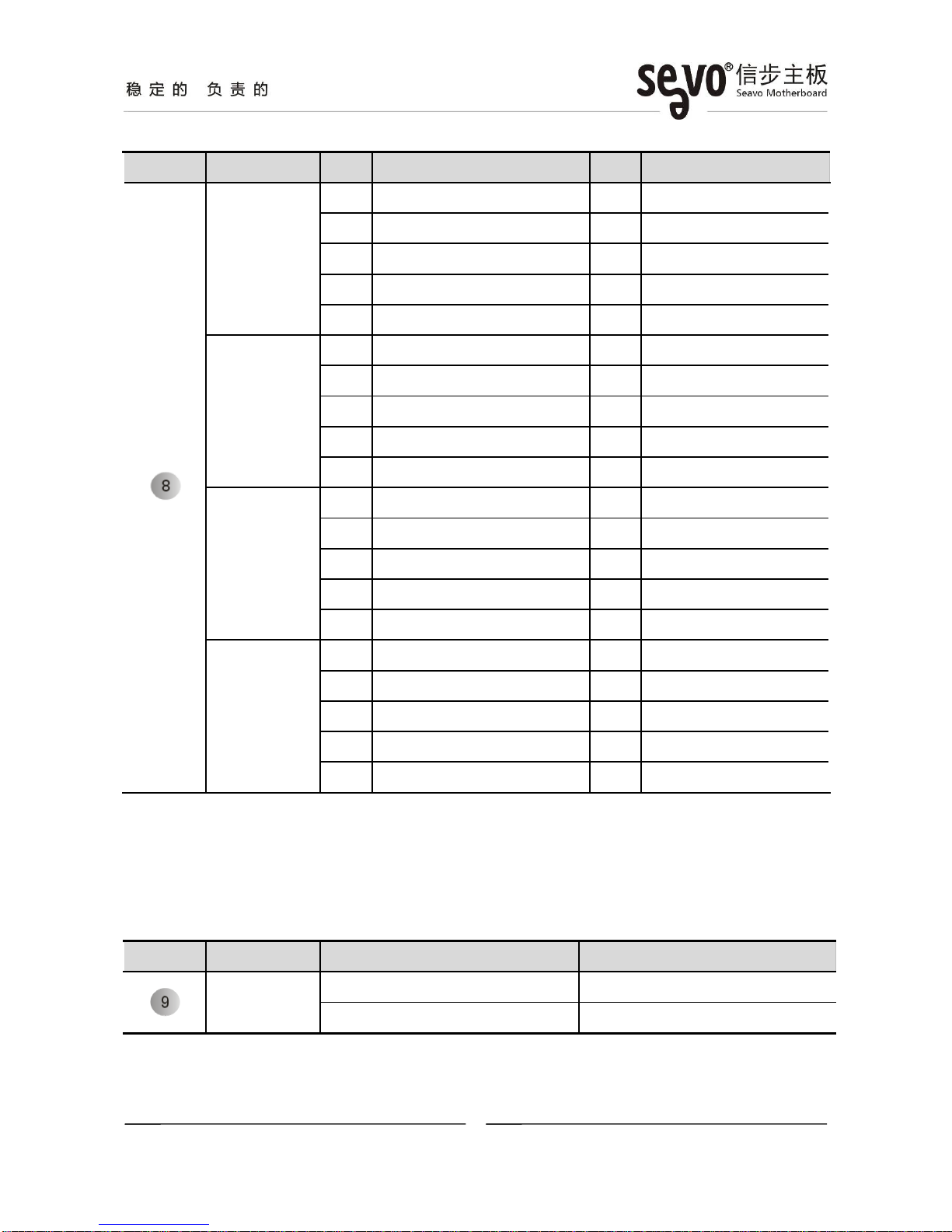
[8] COM1~4 Headers(5*2 Pin 2.54mm)
Location Header Pin Definition Pin Definition
J_COM1
1 JC1* 2 RXD
3 TXD 4 DTR
5 GND 6 DSR
7 RTS 8 CTS
9 RI
J_COM2
1 JC2* 2 RXD
3 TXD 4 DTR
5 GND 6 DSR
7 RTS 8 CTS
9 RI
J_COM3
1 JC3_P* 2 JC3_TTL1* /JC3_TTL2*
3 JC3_TTL1* /JC3_TTL2* 4 DTR
5 GND 6 DSR
7 RTS 8 CTS
9 N/C [1]
J_COM4
1 JC4*2 RXD
3 TXD 4 DTR
5 GND 6 DSR
7 RTS 8 CTS
9 N/C [1]
*These signals are depend on relevant Jumpers (e.g. Pin1 of J_COM1 depends on JC1 Jumper),
to find more details, check the following table (Location 9~12).
Notes:
[1]: Pin9 of J_COM3 and J_COM4 are ”N/C”(default), and 5V or 12V selectable.
[9] COM1 Control Jumper(3*1 Pin 2.00mm)
Location Jumper Settings Function
JC1 1-2 PIN1 :5V
2-3 (Default) PIN1 :DCD

- 10 -
深圳市信步科技有限公司 地址:深圳市福田区车公庙泰然工贸园 210 栋西座 5H T 86-755-88251900 F 86-755-88251910 www.seavo.com
[10] COM2 Control Jumper(3*1 Pin 2.00mm)
Location Jumper Settings Function
JC2 1-2 PIN1:5V
2-3(Default) PIN1:DCD
[11] COM3 Control Jumpers(3*1 Pin 2.00mm)
Location Jumper Setting Function
JC3_TTL1
JC3_TTL2 1-2, 3-4(Default) RS-232
2-3 TTL
JC3_P
1-2 PIN1:5V
2-3 PIN1 :12V
3-4(Default) PIN1:N/C
[12] COM4 Control Jumper(3*1 Pin 2.00mm)
Location Jumper Setting Function
JC4
1-2 PIN1 :5V
2-3 PIN1 :12V
3-4(Default) PIN1:N/C
- 11 -
深圳市信步科技有限公司 地址:深圳市福田区车公庙泰然工贸园 210 栋西座 5H T 86-755-88251900 F 86-755-88251910 www.seavo.com
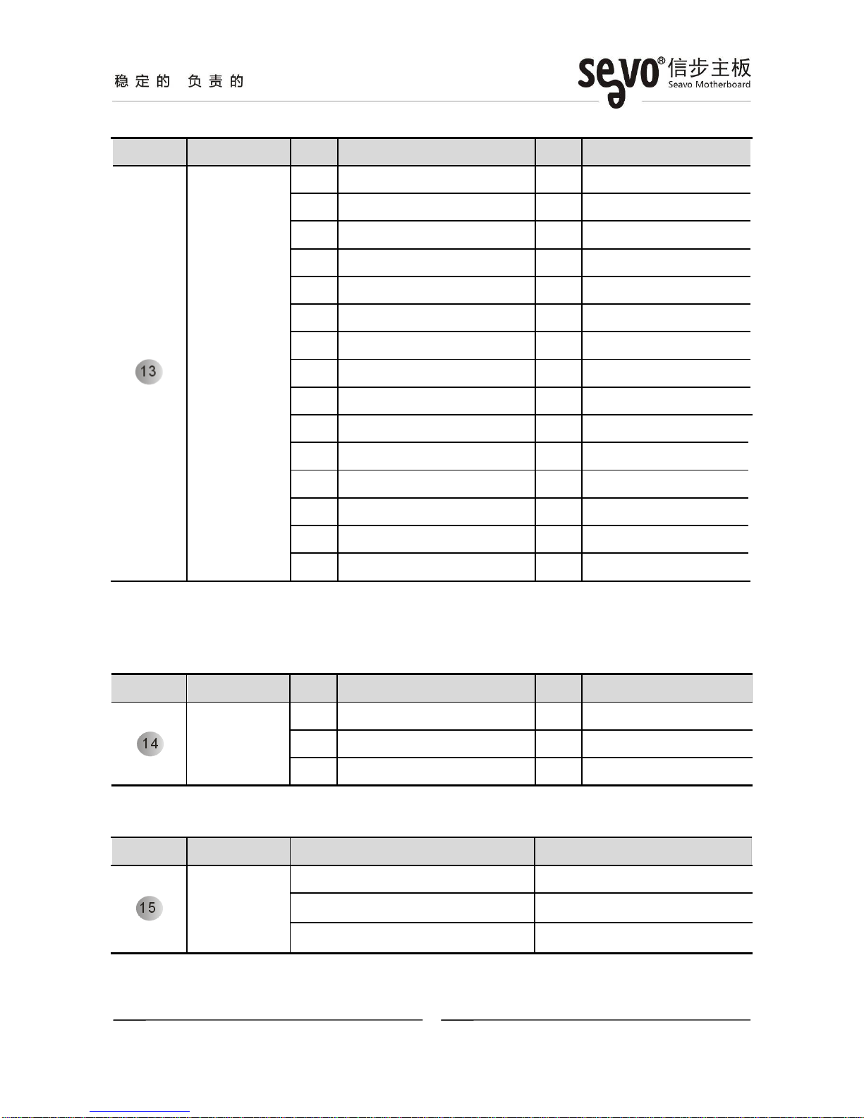
[13] LVDS Header(15*2 Pin 2.00mm)
Location Header Pin Definition Pin Definition
LVDS1
1 VCC [1] 2 VCC [1]
3 VCC [1] 4 N/C
5 GND 6 GND
7 LVDS_A_DATA0_N 8 LVDS_A_DATA0_P
9 LVDS_A_DATA1_N 10 LVDS_A_DATA1_P
11 LVDS_A_DATA2_N 12 LVDS_A_DATA2_P
13 GND 14 GND
15 LVDS_A_CLK_N 16 LVDS_A_CLK_P
17 LVDS_A_DATA3_N 18 LVDS_A_DATA3_P
19 LVDS_B_DATA0_N 20 LVDS_B_DATA0_P
21 LVDS_B_DATA1_N 22 LVDS_B_DATA1_P
23 LVDS_B_DATA2_N 24 LVDS_B_DATA2_P
25 GND 26 GND
27 LVDS_B_CLK_N 28 LVDS_B_CLK_P
29 LVDS_B_DATA3_N 30 LVDS_B_DATA3_P
Notes:
[1]: VCC could be 3.3V (default) or 5V or 12V by setting the jumper “LVDS_P1 (Location 15)”.
[14] LVDS Backlight Control Connector(5*1 Pin 2.00mm)
Location Connector Pin Definition Pin Definition
JP2
1 + 12V 2 GND
3 LVDS_BKL_EN 4 N/C
5 + 5V
[15] LVDS VCC Selection Jumper(3*2 Pin 2.00mm)
Location Jumper Setting Function
LVDS_P1
1-2 + 12V
3-4 + 5V
5-6(Default) + 3.3V
Notes:
[1]: Only one jumper can be installed at once, otherwise, the LVDS device or the motherboard will get
- 12 -
深圳市信步科技有限公司 地址:深圳市福田区车公庙泰然工贸园 210 栋西座 5H T 86-755-88251900 F 86-755-88251910 www.seavo.com
damaged.
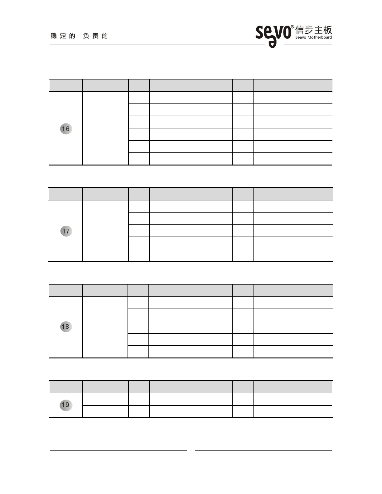
[16] VGA Header(12*1 Pin 2.00 mm)
Location Connector Pin Definition Pin Definition
J_VGA1
1 GND 2 VSYNC
3 HSYNC 4 GND
5 RED 6 GND
7 GREEN 8 GND
9 BLUE 10 GND
11 DDCDAT 12 DDCCLK
[17] Front Panel Header(5*2 Pin 2.54mm)
Location Header Pin Definition Pin Definition
F_PANEL1
1 HD LED+ 2 Power LED+
3 HD LED- 4 Power LED-
5 RESET+ 6 PWR+
7 RESET- 8 PWR-
9 N/C
[18] FrontAudio Header(5*2 Pin 2.54mm)
Location Header Pin Definition Pin Definition
F_AUDIO1
1 FP_MIC_L 2 GND
3 FP_MIC_R 4 AUD_VCC
5 FP_OUT_R 6 SENSE1_RETURN
7 SENSE_SEND
9 FP_OUT_L 10 SENSE2_RETURN
[19] Amplifier Headers(2*1 Pin 2.00mm)
Location Header Pin Definition Pin Definition
J_SPK_R 1 SPKR_R- 2 SPKR_R+
J_SPK_L1 SPKR_L+ 2 SPKR_L-

- 13 -
深圳市信步科技有限公司 地址:深圳市福田区车公庙泰然工贸园 210 栋西座 5H T 86-755-88251900 F 86-755-88251910 www.seavo.com
[20] CMOS Clear Jumper(3*1 Pin 2.54mm)
Location Jumper Setting Function
JCMOS1 1-2(Default) Normal
2-3 Clear CMOS
[21] LPT Header (13*2 Pin 2.0mm)
Location Header Pin Definition Pin Definition
J_LPT1
1 STB 2 -AFD
3 DATA0 4 -ERR
5 DATA1 6 -PINIT
7 DATA2 8 -SLIN
9 DATA3 10 GND
11 DATA4 12 GND
13 DATA5 14 GND
15 DATA6 16 GND
17 DATA7 18 GND
19 -ACK 20 GND
21 BUSY 22 GND
23 PE 24 GND
25 SLCT 26 GND
[22] Keyboard and Mouse Header (6*1 Pin 2.0mm)
Location Header Pin Definition Pin Definition
J_KBMS1
1 KB_CLK 2 KB_DATA
3 MS_CLK 4 GND
5 + 5V 6 MS_DATA
[23] System Fan Headers(3*1 Pin 2.54mm/4*1 Pin 2.54mm)
Location Header Pin Definition Pin Definition
SYS_FAN1 1 GND 2 + 12V
3 N/C
SYS_FAN2 1 GND 2 + 12V
3 FAN Speed Detect 4 FAN Speed Control
- 14 -
深圳市信步科技有限公司 地址:深圳市福田区车公庙泰然工贸园 210 栋西座 5H T 86-755-88251900 F 86-755-88251910 www.seavo.com
[24] Power-on Signal Selection Jumper(3*1 Pin 2.00mm)
Location Jumper Settings Function
JP3 1-2(Default) Power-on signal from SIO [1]
2-3 Power-on signal from ICH [1]
Notes:
[1]: Different power-on signal selection needs corresponding BIOS supported.
6. BIOS setup
See “SV1a-25514P BIOS User Manual” for detail information of BIOS setup.
【End】
Table of contents
Other Seavo Motherboard manuals


