SEC 611HS User manual

SEC
SEC America, LLC
www.secamerica.com
USER MANUAL
600HS Series
DC-DC Converters
Applies to Models:
611HS 637HS
621HS 649HS
March 10, 2016

TABLE OF CONTENTS
page
I Introduction 1
II Installation 1
2.1 Mounting 1
2.2 Connections 1
2.3 Mechanical Drawing 2
III Remote Sense Regulation 2
IV User Adjustments 3
IVWarranty 4
V Electrical Specifications 5-8
I Introduction
After removing the unit from its packaging and ensuring that it has suffered no damage in shipment, it
is important to read this manual and follow its instructions to ensure proper connection and mounting.
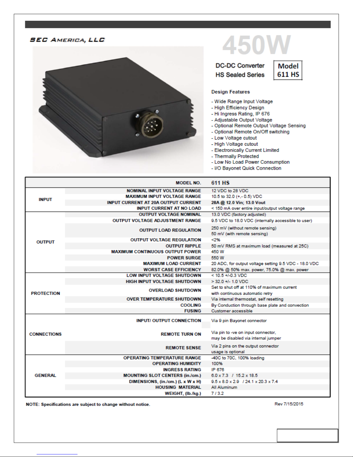
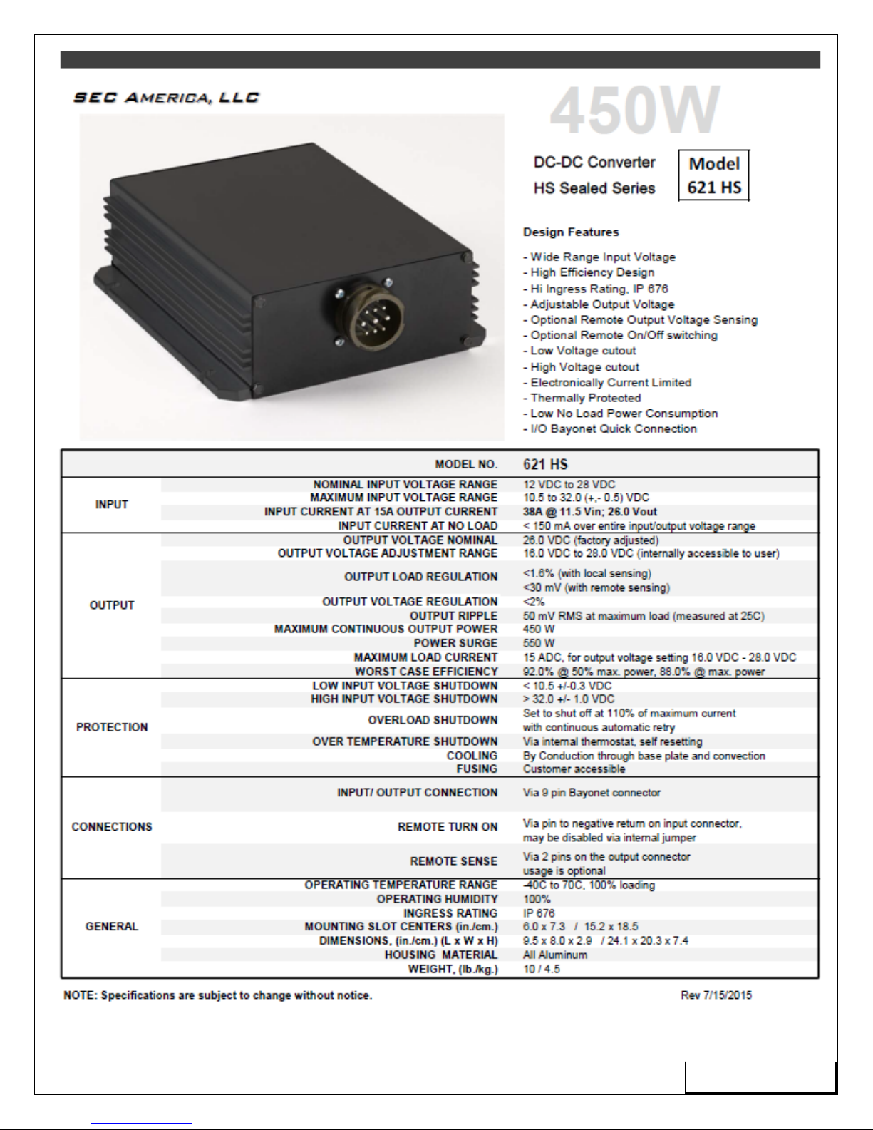
600HS Series models are fully isolated dc-dc converters capable of delivering up to 450 Watts in
extreme ambient temperatures and adverse operating conditions. See specification sheets at the end
of this manual for the ratings of a particular model.
II Installation
2.1 Mounting
The converters are designed to be mounted to flat metal surfaces offering optimum heat transfer from
the converter base in environments where air flow may be restricted. For best results, thermal
transfer compound is a recommended interface between the converter and mounting surface. The [4]
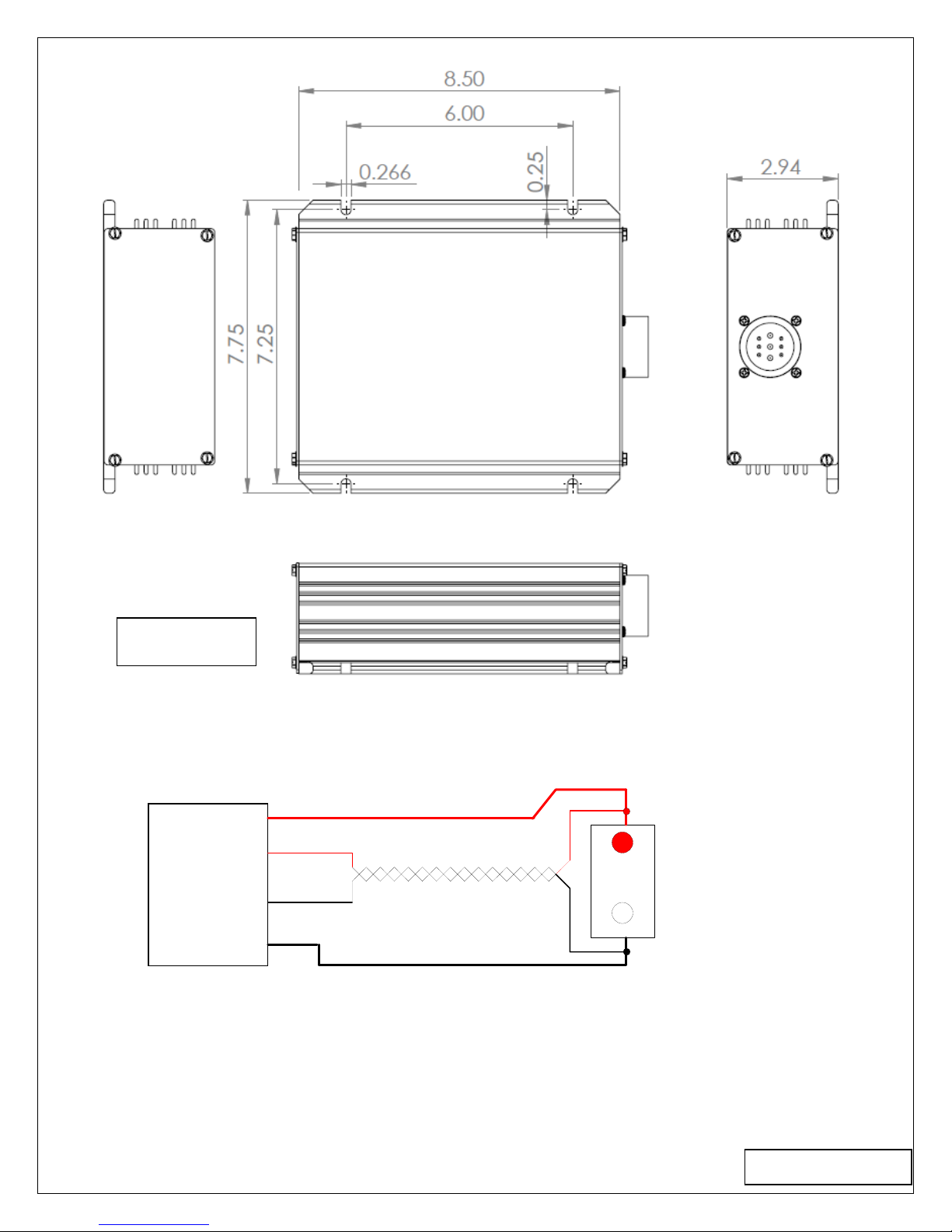
mounting slots in the flanges will accommodate mounting hardware up to ¼ inch diameter. (See
figure #2 for mounting centers)
2.2 Connections
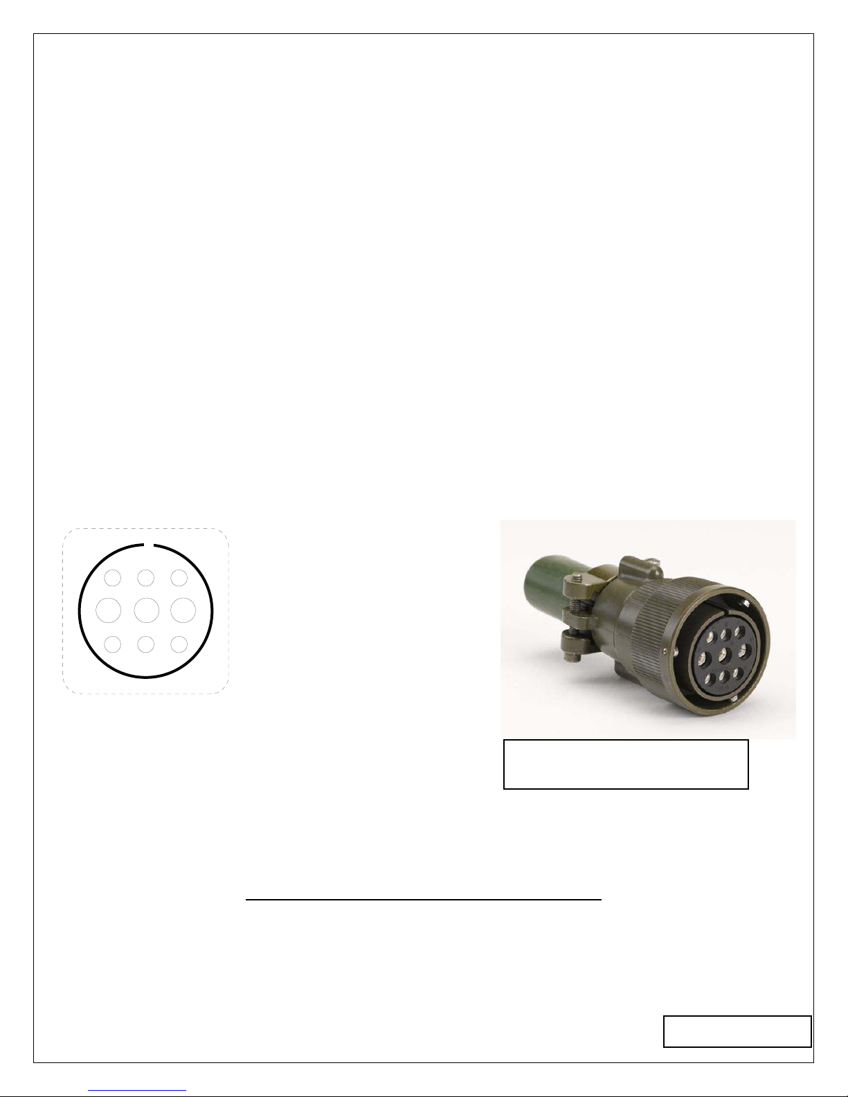
The Input/Output connector on the converter is shown in Figure 1
with designated pin functions.
Input/Output Connector A - Output Positive Sense
B - No Connection
C - Output Negative Sense
D - Input Positive
Canon 3102E24-11PB
Pin
ABC
DEF
GHI
E - Housing Ground
F - Input Negative
G - Output Positive
H - Remote Turn On/Off
I - Output Negative
Front View
key
Figure 1 Figure 1A
Pins Maximum Wire Sizes
D,E,F #8
Others #12
An option for users who wish to purchase a manufactured cable assembly is P/N 68-0749-6 which is
6 feet long and is a standard SEC part.
Cable side mating connector
Canon P/N 3106E24-11SB
Page 1
III Regulation With Remote Sense
+Vo
+S
-Vo
-S
HS
DC-DC
Converter Load
+
-
twisted pair Figure 3
G
A
C
I
Pin
TheHSSeriesprovidesregulatedoutputsattheoutputterminals.Whenthereisalargecurrentand/orthe
outputcableisofsomelength,thevoltageattheendofthecablemaybenoticeablylowerthanatthe
terminals.Theconvertercancompensateupto0.75Vofvoltagedropthroughremotesenseterminals.To
ensureaccurateregulation,usersshouldruntwoseparatewires(twistedfromthedesiredregulationpointsto
theremotesenseterminals.Eveniftheloadcurrentislow,usersshouldstillconnect+Voto+Sand–Voto–S.
Figure 2
Page 2
A
ll dimensions are in inches

IV User Adjustments
Series 600HS units are gasket-sealed. Changes or adjustments to the operating modes of any unit
are accomplished internally:
1) To gain access, remove the 4 corner screws retaining the connector plate as shown in Figure
#4. Disconnect power from the unit before opening it.
2) After removing the screws, lift the panel to expose the internal components as shown. Figure
#5 shows the adjustments and their locations
With P/N ATC 30
Replace Fuses
ATC 30
123
jumper 2,3 - Unit ON
jumper 1,2 - ON by Remote Pin
Output Voltage
Adjustment jumper
P1 CON1 F1,2
Figure 5
Accessible Adjustments:
A) Output voltage is trimmed by adjusting the potentiometer P1.
B) Remote “Turn On” Disabled: Units are shipped from factory with pins 2 and 3 of the
connector [CON1] jumpered as shown. This programs the unit to be “ON” when source power
is applied.
C) Remote “Turn On” Enabled: To program the unit for remote enable, shift the jumper from
pin positions 2 and 3 of [CON1] to positions 1 and 2. In this mode the unit will energize when
pin H is connected to the negative input line pin F. Page 3
Figure 4

D) Fuse Replacement: In the unlikely event that fuses F1,2 will open, disabling the unit, DO
NOT CHANGE FUSES WITH THE POWER APPLIED. In order to restore normal operation,
the user will need to ensure that the cause of the failure has been removed. Then the blown
fuses need to be removed by gently prying them out of their clips and replacing them with ones
of identical ratings. Notwithstanding the above the user should take every precaution to ensure
that a reversed polarity input is avoided. Any polarity reversals may result in permanent
damage.
3) Restore the front plate to its orginal position by replacing the securing screws and making sure
the gasket is compressed.
IV Warranty and Repair
Should your investigations indicate that your product is defective or damaged and the unit is still
under warranty, contact your dealer (purchase point of origin) and obtain a return merchandise
authorization (RMA number) for corrective action.
If the warranty period has expired or if the warranty has been violated due to operator error or misuse
call: SEC America, LLC, 802-865-8388 to receive an authorization for return for an assessment and
possible repair.
Warranty
600HS Series models come with a 2 year factory warranty covering parts and labor per the
following:
We warrant each instrument, sold by us, or our authorized agents, to be
free from defects in material and workmanship and that it will perform
within applicable specifications for a period of two year after original
shipment. Our obligation under this guarantee is limited to repairing or
replacing any instrument or any part thereof,except fuses and pilot lights,
which shall within one year after delivery to the original purchaser, be
returned to us with transportation charges prepaid, prove after our exa-
mination to be thus defective.
LIMITED WARRANTY
The above limited warranties take the place of all other warranties,
expressed or implied, and correction of such defects by replacement or
repair shall constitute a fulfillment of all obligations under the terms of the
warranties. The warranties do not cover any unit that has been damaged
either in transit or by misuse, accident or negligence. No warranty or re-
presentation by anyone other than this Company shall be binding on us.
To return a unit to factory, send only to the following address:
SEC America, LLC
78 Ethan Allen Drive
South Burlington, Vermont 05403
PLEASE RETAIN YOUR ORIGINAL BILL OF SALE. IT MUST
BE SUBMITTED WHEN MAKING ANY WARRANTY CLAIM
Tel: 802-865-8388
Page 4
Page 5
Page 6

Page 7

Page 8

SEC
SEC America, LLC
P.O. Box 2266
South Burlington 78 Ethan Allen Drive
VT 05403 www.secamerica.com
Tel: 802-865-8388 Fax: 802-865-8389
cage code 07KU1
Copyright - March 2016 All rights reserved Printed in U.S.A.
This manual suits for next models
3
Table of contents
Other SEC Media Converter manuals


Popular Media Converter manuals by other brands


DOREMIDI
DOREMIDI MPC-10 instructions

CommFront
CommFront FBR-Serial-2 quick start guide

ZyCast
ZyCast digi-MOD Series User guide & installation manual

National Instruments
National Instruments GPIB-RS232 installation guide

Black Iris For Telecom & Technology
Black Iris For Telecom & Technology ETH-FE1 Data sheet & user manual

KROHNE
KROHNE IFC 050 quick start


