KROHNE IFC 050 User manual

Signal converter for electromagnetic flowmeters
Electronic revision:
ER 3.0.xx
IFC 050
IFC 050IFC 050
IFC 050 Quick Start
Quick StartQuick Start
Quick Start
© KROHNE 10/2012 - 4002257401 - QS IFC 050 R01 en
The documentation is only complete when used in combination with the relevant
documentation for the measuring sensor.

CONTENTS
2 www.krohne.com 10/2012 - 4002257401 - QS IFC 050 R01 en
IFC 050
1 Safety instructions 3
2 Installation 4
2.1 Intended use ..................................................................................................................... 4
2.2 Scope of delivery............................................................................................................... 4
2.3 Storage ............................................................................................................................. 5
2.4 Transport .......................................................................................................................... 5
2.5 Installation specifications ................................................................................................5
2.6 Mounting of the compact version..................................................................................... 6
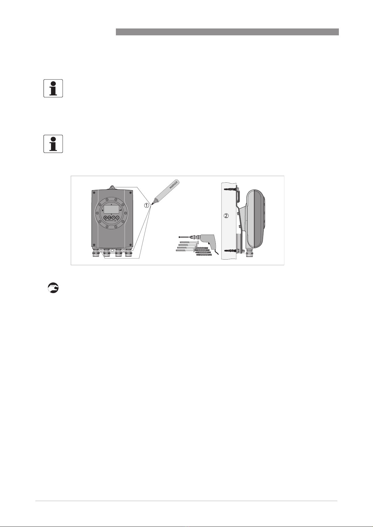
2.7 Mounting of the wall housing, remote version ................................................................ 6
3 Electrical connections 8
3.1 Safety instructions............................................................................................................ 8
3.2 Important notes on electrical connection........................................................................ 8
3.3 Electrical cables for remote device versions, notes........................................................ 9
3.3.1 Notes on signal cable A .......................................................................................................... 9
3.3.2 Notes on field current cable C................................................................................................ 9
3.3.3 Requirements for signal cables provided by the customer ................................................. 10
3.4 Preparing the signal and field current cables ............................................................... 11
3.4.1 Signal cable A (type DS 300), construction........................................................................... 11
3.4.2 Preparing signal cable A, connection to signal converter ................................................... 12
3.4.3 Length of signal cable A........................................................................................................ 13
3.4.4 Preparing field current cable C, connection to signal converter......................................... 14
3.4.5 Preparing signal cable A, connection to measuring sensor................................................ 16
3.4.6 Preparing field current cable C, connection to measuring sensor ..................................... 17
3.5 Connecting the signal and field current cables............................................................. 18
3.5.1 Connecting the signal and field current cables to the signal converter, remote version... 18
3.5.2 Connection diagram for signal and field current cable ....................................................... 19
3.6 Grounding the measuring sensor .................................................................................. 20
3.7 Connecting the power supply......................................................................................... 20
3.8 Overview of outputs ........................................................................................................22
3.8.1 Description of the CG number .............................................................................................. 22
3.8.2 Fixed, non-alterable output versions ................................................................................... 22
3.9 Electrical connection of the outputs .............................................................................. 23
3.9.1 Electrical connection of the outputs.....................................................................................23
3.9.2 Laying electrical cables correctly......................................................................................... 24
4 Start-up 25
4.1 Switching on the power .................................................................................................. 25
4.2 Starting the signal converter ......................................................................................... 25
5 Notes 26

SAFETY INSTRUCTIONS 1
3
IFC 050
www.krohne.com10/2012 - 4002257401 - QS IFC 050 R01 en
Warnings and symbols used
HANDLING
• This symbol designates all instructions for actions to be carried out by the operator in the
specified sequence.
iRESULT
RESULTRESULT
RESULT
This symbol refers to all important consequences of the previous actions.
Safety instructions for the operator
DANGER!
This information refers to the immediate danger when working with electricity.
DANGER!
These warnings must be observed without fail. Even partial disregard of this warning can lead to
serious health problems and even death. There is also the risk of seriously damaging the device
or parts of the operator's plant.
WARNING!
Disregarding this safety warning, even if only in part, poses the risk of serious health problems.
There is also the risk of damaging the device or parts of the operator's plant.
CAUTION!
Disregarding these instructions can result in damage to the device or to parts of the operator's
plant.
INFORMATION!
These instructions contain important information for the handling of the device.
CAUTION!
Installation, assembly, start-up and maintenance may only be performed by appropriately
trained personnel. The regional occupational health and safety directives must always be
observed.
LEGAL NOTICE!
The responsibility as to the suitability and intended use of this device rests solely with the user.
The supplier assumes no responsibility in the event of improper use by the customer. Improper
installation and operation may lead to loss of warranty. In addition, the "Terms and Conditions of
Sale" apply which form the basis of the purchase contract.
INFORMATION!
•
Further information can be found on the supplied CD-ROM in the manual, on the data sheet,
in special manuals, certificates and on the manufacturer's website.
•
If you need to return the device to the manufacturer or supplier, please fill out the form
contained on the CD-ROM and send it with the device. Unfortunately, the manufacturer
cannot repair or inspect the device without the completed form.

2INSTALLATION
4
IFC 050
www.krohne.com 10/2012 - 4002257401 - QS IFC 050 R01 en
2.1 Intended use
The electromagnetic flowmeters are designed exclusively to measure the flow and conductivity
of electrically conductive, liquid media.
2.2 Scope of delivery
WARNING!
If the device is not used according to the operating conditions, the intended protection could be
affected.
INFORMATION!
Inspect the cartons carefully for damages or signs of rough handling. Report damage to the
carrier and to the local office of the manufacturer.
INFORMATION!
Do a check of the packing list to make sure that you have all the elements given in the order.
INFORMATION!
Look at the device nameplate to ensure that the device is delivered according to your order.
Check for the correct supply voltage printed on the nameplate.
Figure 2-1: Scope of delivery
1 Device in the version as ordered
2 Documentation (calibration report, Quick Start, CD-ROM with product documentation for measuring sensor and signal
converter)
3 Signal cable (only for remote version)

INSTALLATION 2
5
IFC 050
www.krohne.com10/2012 - 4002257401 - QS IFC 050 R01 en
2.3 Storage
•Store the device in a dry, dust-free location.
•Avoid continuous direct sunlight.
•Store the device in its original packing.
•Storage temperature: -40...+70°C / -40...+158°F
2.4 Transport
Signal converter
•No special requirements.
Compact version
•Do not lift the device by the signal converter housing.
•Do not use lifting chains.
•To transport flange devices, use lifting straps. Wrap these around both process connections.
2.5 Installation specifications
INFORMATION!
The following precautions must be taken to ensure reliable installation.
•
Make sure that there is adequate space to the sides.
•
Protect the signal converter from direct sunlight and install a sun shade if necessary.
•
Signal converters installed in control cabinets require adequate cooling, e.g. by fan or heat
exchanger.
•
Do not expose the signal converter to intense vibration. The flowmeters are tested for a
vibration level in accordance with IEC 68-2-64.

2INSTALLATION
6
IFC 050
www.krohne.com 10/2012 - 4002257401 - QS IFC 050 R01 en
2.6 Mounting of the compact version
2.7 Mounting of the wall housing, remote version
1 Prepare the holes with the aid of the mounting plate.
2 Fasten the device securely to the wall with the mounting plate.
INFORMATION!
The signal converter is mounted directly on the measuring sensor. For installation of the
flowmeter, please observe the instructions in the supplied product documentation for the
measuring sensor.
INFORMATION!
Assembly materials and tools are not part of the delivery. Use the assembly materials and tools
in compliance with the applicable occupational health and safety directives.
Figure 2-2: Mounting of the wall housing

INSTALLATION 2
7
IFC 050
www.krohne.com10/2012 - 4002257401 - QS IFC 050 R01 en
Mounting multiple devices next to each other
[mm] [inch]
aØ6.5 Ø0.26
b80 3.15
c248 9.76
d310 12.2
e257 10.1

3ELECTRICAL CONNECTIONS
8
IFC 050
www.krohne.com 10/2012 - 4002257401 - QS IFC 050 R01 en
3.1 Safety instructions
3.2 Important notes on electrical connection
DANGER!
All work on the electrical connections may only be carried out with the power disconnected. Take
note of the voltage data on the nameplate!
DANGER!
Observe the national regulations for electrical installations!
WARNING!
Observe without fail the local occupational health and safety regulations. Any work done on the
electrical components of the measuring device may only be carried out by properly trained
specialists.
INFORMATION!
Look at the device nameplate to ensure that the device is delivered according to your order.
Check for the correct supply voltage printed on the nameplate.
DANGER!
Electrical connection is carried out in conformity with the VDE 0100 directive "Regulations for
electrical power installations with line voltages up to 1000 V" or equivalent national
specifications.
CAUTION!
•
Use suitable cable entries for the various electrical cables.
•
The measuring sensor and signal converter have been configured together at the factory. For
this reason, please connect the devices in pairs. Ensure that the measuring sensor constant
GKL (refer to information on the nameplates) are identically set.
•
If delivered separately or when installing devices that were not configured together, set the
signal converter to the DN size and GKL of the measuring sensor.

ELECTRICAL CONNECTIONS 3
9
IFC 050
www.krohne.com10/2012 - 4002257401 - QS IFC 050 R01 en
3.3 Electrical cables for remote device versions, notes
3.3.1 Notes on signal cable A
Observe the following notes:
•Lay the signal cable with fastening elements.
•It is permissible to lay the signal cable in water or in the ground.
•The insulating material is flame-retardant to EN 50625-2-1, IEC 60322-1.
•The signal cable does not contain any halogens and is unplasticized, and remains flexible at
low temperatures.
•The connection of the inner shield (10) is carried out via the stranded drain wire (1).
•The connection of the outer shield (60) is carried out via the stranded drain wire (6).
3.3.2 Notes on field current cable C
INFORMATION!
Signal cable A (type DS 300) with double shield ensures proper transmission of measured
values.
DANGER!
A shielded 2-wire copper cable is used for the field current cable. The shielding MUST
MUSTMUST
MUST be
connected in the housing of the measuring sensor and signal converter.
INFORMATION!
The field current cable is not part of the scope of delivery.

3ELECTRICAL CONNECTIONS
10
IFC 050
www.krohne.com 10/2012 - 4002257401 - QS IFC 050 R01 en
3.3.3 Requirements for signal cables provided by the customer
Electrical safety
•To EN 60811 (Low Voltage Directive) or equivalent national regulations.
Capacitance of the insulated conductors
•Insulated conductor / insulated conductor < 50 pF/m
•Insulated conductor / shield < 150 pF/m
Insulation resistance
•Riso > 100 GΩxkm
•Umax < 24 V
•Imax < 100 mA
Test voltages
•Insulated conductor / inner shield 500 V
•Insulated conductor / insulated conductor 1000 V
•Insulated conductor / outer shield 1000 V
Twisting of the insulated conductors
•At least 10 twists per meter, important for screening magnetic fields.
INFORMATION!
If the signal cable was not ordered, it is to be provided by the customer. The following
requirements regarding the electrical values of the signal cable must be observed:

ELECTRICAL CONNECTIONS 3
11
IFC 050
www.krohne.com10/2012 - 4002257401 - QS IFC 050 R01 en
3.4 Preparing the signal and field current cables
3.4.1 Signal cable A (type DS 300), construction
•Signal cable A is a double-shielded cable for signal transmission between the measuring
sensor and signal converter.
•Bending radius: ≥50 mm / 2"
INFORMATION!
Assembly materials and tools are not part of the delivery. Use the assembly materials and tools
in compliance with the applicable occupational health and safety directives.
Figure 3-1: Construction of signal cable A
1 Stranded drain wire (1) for the inner shield (10), 1.0 mm2Cu / AWG 17 (not insulated, bare)
2 Insulated wire (2), 0.5 mm2Cu / AWG 20
3 Insulated wire (3), 0.5 mm2Cu / AWG 20
4 Outer sheath
5 Insulation layers
6 Stranded drain wire (6) for the outer shield (60)

3ELECTRICAL CONNECTIONS
12
IFC 050
www.krohne.com 10/2012 - 4002257401 - QS IFC 050 R01 en
3.4.2 Preparing signal cable A, connection to signal converter
•Connection of the two shields in the signal converter is carried out via the stranded drain
wires.
•Bending radius: ≥50 mm / 2"
Required materials
•PVC insulating tube, Ø2.5 mm / 0.1"
•Heat-shrinkable tubing
•2 wire end ferrules to DIN 46 228: E 1.5-8 for the stranded drain wires (1, 6)
•2 wire end ferrules to DIN 46 228: E 0.5-8 for the insulated conductors (2, 3)
1 Strip the conductor to dimension a.
2 Cut off the inner shield (10) and the outer shield (60). Make sure not to damage the stranded
drain wires (1, 6).
3 Slide the insulating tubes over the stranded drain wires (1, 6).
4 Crimp the wire end ferrules onto the stranded drain wire.
5 Crimp the wire end ferrules onto the conductors (2, 3).
6 Pull the heat-shrinkable tubing over the prepared signal cable.
INFORMATION!
Assembly materials and tools are not part of the delivery. Use the assembly materials and tools
in compliance with the applicable occupational health and safety directives.
Figure 3-2: Preparation of signal cable A
a = 80 mm / 3.15"

ELECTRICAL CONNECTIONS 3
13
IFC 050
www.krohne.com10/2012 - 4002257401 - QS IFC 050 R01 en
3.4.3 Length of signal cable A
INFORMATION!
For temperatures of the medium above 150
°
C / 300
°
F, a special signal cable and a ZD
intermediate socket are necessary. These are available including the changed electrical
connection diagrams.
Measuring sensor Nominal meter size Min. electrical
conductivity
[µS/cm]
Curve for signal
cable A
DN [mm] [inch]
OPTIFLUX 1000 F 10...150 3/8...6 20 A1
OPTIFLUX 2000 F 25...150 1...6 20 A1
200...1200 8...48 20 A2
WATERFLUX 3000 F 25...600 1...24 20 A1
Figure 3-3: Maximum length of signal cable A
1 Maximum length of signal cable A between the measuring sensor and signal converter [m]
2 Maximum length of signal cable A between the measuring sensor and signal converter [ft]
3 Electrical conductivity of the medium being measured [μS/cm]

3ELECTRICAL CONNECTIONS
14
IFC 050
www.krohne.com 10/2012 - 4002257401 - QS IFC 050 R01 en
3.4.4 Preparing field current cable C, connection to signal converter
•Field current cable C is not part of the scope of delivery.
•Bending radius: ≥50 mm / 2"
Required materials:
•Shielded, at least 2-wire copper cable with suitable heat-shrinkable tubing
•Insulating tube, size according to the cable being used
•Wire end ferrules to DIN 46 228: size according to the cable being used
Length and cross-section of field current cable C
DANGER!
A shielded 2-wire copper cable is used as the field current cable. The shielding MUST
MUSTMUST
MUST be
connected in the housing of the measuring sensor and signal converter.
INFORMATION!
Assembly materials and tools are not part of the delivery. Use the assembly materials and tools
in compliance with the applicable occupational health and safety directives.
Length Cross-section AF(Cu)
[m] [ft] [mm2][AWG]
0...150 0...492 2 x 0.75 Cu 1 2 x 18
150...300 492...984 2 x 1.5 Cu 1 2 x 14
300...600 984...1968 2 x 2.5 Cu 1 2 x 12
1Cu = copper cross-section

ELECTRICAL CONNECTIONS 3
15
IFC 050
www.krohne.com10/2012 - 4002257401 - QS IFC 050 R01 en
1 Strip the conductor to dimension a.
2 If a stranded drain wire is present, remove the shield that is present. Make sure not to damage
the stranded drain wire.
3 Slide an insulating tube over the stranded drain wire.
4 Crimp a wire end ferrule onto the stranded drain wire.
5 Crimp the wire end ferrules on the conductors.
6 Pull a shrinkable tube over the prepared cable.
Figure 3-4: Field current cable C, preparation for the signal converter
a = 80 mm / 3.15"

3ELECTRICAL CONNECTIONS
16
IFC 050
www.krohne.com 10/2012 - 4002257401 - QS IFC 050 R01 en
3.4.5 Preparing signal cable A, connection to measuring sensor
•The outer shield (60) is connected in the terminal compartment of the measuring sensor
directly via the shield and a clip.
•Bending radius: ≥50 mm / 2"
Required materials
•PVC insulating tube, Ø2.0...2.5 mm / 0.08...0.1"
•Heat-shrinkable tubing
•Wire end ferrule to DIN 46 228: E 1.5-8 for the stranded drain wire (1)
•2 wire end ferrules to DIN 46 228: E 0.5-8 for the insulated conductors (2, 3)
1 Strip the conductor to dimension a.
2 Trim the outer shield (60) to dimension b and pull it over the outer sheath.
3 Remove the stranded drain wire (6) of the outer shield and the inner shield. Make sure not to
damage the stranded drain wire (1) of the inner shield.
4 Slide an insulating tube over the stranded drain wire (1).
5 Crimp the wire end ferrules onto conductors 2 and 3 and the stranded drain wire (1).
6 Pull the heat-shrinkable tubing over the prepared signal cable.
INFORMATION!
Assembly materials and tools are not part of the delivery. Use the assembly materials and tools
in compliance with the applicable occupational health and safety directives.
Figure 3-5: Preparing signal cable A, connection to measuring sensor
a = 50 mm / 2"
b = 10 mm / 0.39"

ELECTRICAL CONNECTIONS 3
17
IFC 050
www.krohne.com10/2012 - 4002257401 - QS IFC 050 R01 en
3.4.6 Preparing field current cable C, connection to measuring sensor
•The field current cable is not included in delivery.
•The shield is connected in the terminal compartment of the measuring sensor directly via the
shield and a clip.
•Bending radius: ≥50 mm / 2"
Required materials
•Shielded 2-wire insulated copper cable
•Insulating tube, size according to the cable being used
•Heat-shrinkable tubing
•Wire end ferrules to DIN 46 228: size according to the cable being used
1 Strip the conductor to dimension a.
2 Trim the outer shield to dimension b and pull it over the outer sheath.
3 Crimp wire end ferrules onto both conductors.
4 Pull a shrinkable tube over the prepared cable.
INFORMATION!
Assembly materials and tools are not part of the delivery. Use the assembly materials and tools
in compliance with the applicable occupational health and safety directives.
Figure 3-6: Preparation of field current cable C
a = 50 mm / 2"
b = 10 mm / 0.4"

3ELECTRICAL CONNECTIONS
18
IFC 050
www.krohne.com 10/2012 - 4002257401 - QS IFC 050 R01 en
3.5 Connecting the signal and field current cables
3.5.1 Connecting the signal and field current cables to the signal converter, remote
version
Connect the electrical conductors as follows:
1 Press with a screwdriver in the slot on the spring terminal.
2 Insert the electrical conductor into the plug.
3 The conductor will be clamped as soon as the screwdriver is pulled out of the slot.
DANGER!
Cables may only be connected when the power is switched off.
DANGER!
The device must be grounded in accordance with regulations in order to protect personnel
against electric shocks.
WARNING!
Observe without fail the local occupational health and safety regulations. Any work done on the
electrical components of the measuring device may only be carried out by properly trained
specialists.
INFORMATION!
The compact version is supplied preassembled from the factory.
Figure 3-7: Connecting the signal and field current cables
1 Cable entry for field current cable
2 Cable entry for signal cable
3 Electrical conductor (7)
4 Electrical conductor (8)
5 Connecting the field current cable shield
6 Stranded drain wire (1) of the inner shield (10) of the signal cable
7 Electrical conductor (2)
8 Electrical conductor (3)
9 Stranded drain wire (S) of the outer shield (60)

ELECTRICAL CONNECTIONS 3
19
IFC 050
www.krohne.com10/2012 - 4002257401 - QS IFC 050 R01 en
3.5.2 Connection diagram for signal and field current cable
•A shielded 2-wire copper cable is used as the field current cable. The shielding MUST
MUSTMUST
MUST be
connected in the housing of the measuring sensor and signal converter.
•The outer shield (60) is connected in the terminal compartment of the measuring sensor
directly via the shield and a clip.
•Bending radius of signal and field current cable: ≥50 mm / 2"
•The following illustration is schematic. The positions of the electrical connection terminals
may vary depending on the housing version.
DANGER!
The device must be grounded in accordance with regulations in order to protect personnel
against electric shocks.
Figure 3-8: Connection diagram for signal and field current cable
1 Electrical terminal compartment in signal converter
2 Signal cable A
3 Field current cable C
4 Electrical terminal compartment in measuring sensor
5 Functional ground FE

3ELECTRICAL CONNECTIONS
20
IFC 050
www.krohne.com 10/2012 - 4002257401 - QS IFC 050 R01 en
3.6 Grounding the measuring sensor
•The measuring sensor must be properly grounded.
•The grounding cable should not transmit any interference voltages.
•Do not use the grounding cable to connect any other electrical devices to ground at the same
time.
•The measuring sensors are connected to ground by means of a functional grounding
conductor FE.
•Special grounding instructions for the various measuring sensors are provided in the
separate documentation for the measuring sensor.
•The documentation for the measuring sensor also contain descriptions on how to use
grounding rings and how to install the measuring sensor in metal or plastic pipes or in pipes
which are coated on the inside.
3.7 Connecting the power supply
•The housings of the devices, which are designed to protect the electronic equipment from
dust and moisture, should be kept well closed at all times. Creepage distances and
clearances are dimensioned to VDE 0110 and IEC 664 for pollution severity 2. Supply circuits
are designed for overvoltage category III and the output circuits for overvoltage category II.
•Fuse protection (IN≤16 A) for the infeed power circuit, and also a separator (switch, circuit
breaker) to isolate the signal converter must be provided.
CAUTION!
There should be no difference in potential between the measuring sensor and the housing or
protective earth of the signal converter!
DANGER!
•
To protect operators from electrical shock, during installation the cable for the power supply
must
mustmust
must be run with sheathing insulation up to the mains cover. The insulated individual wires
have to be only below the mains cover!
•
If there is no mains cover or if it has been lost, the 100...230 VAC device may only be operated
from the outside (with a bar magnet) while closed!
Other manuals for IFC 050
2
Table of contents
Other KROHNE Media Converter manuals

KROHNE
KROHNE H250 M40 ESK4-Basic User manual

KROHNE
KROHNE IFC 090 K User manual

KROHNE
KROHNE IFC 070 User manual

KROHNE
KROHNE ifc 300 User manual

KROHNE
KROHNE UFC 400 Wiring diagram

KROHNE
KROHNE UFC 400 Wiring diagram

KROHNE
KROHNE IFC 010 K User manual

KROHNE
KROHNE MFC 400 Wiring diagram

KROHNE
KROHNE MFC 081 Operating instructions

KROHNE
KROHNE UFC 400 Wiring diagram