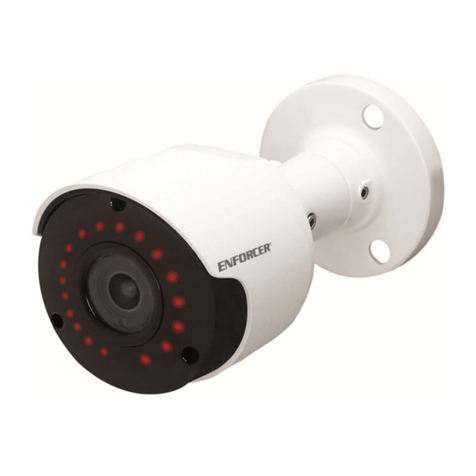
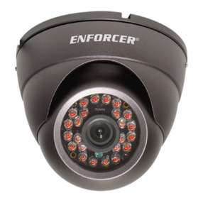
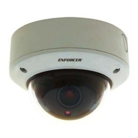
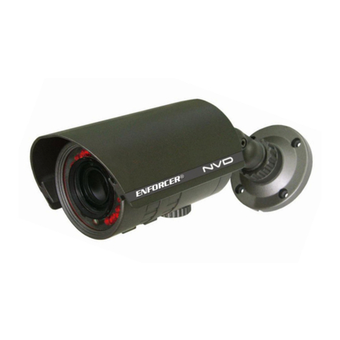
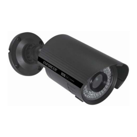
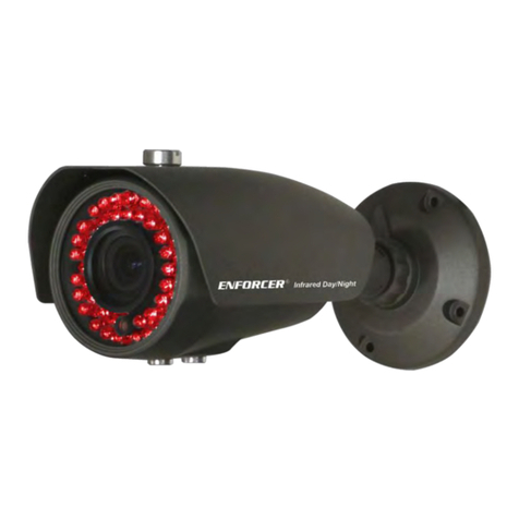
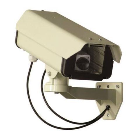
ENFORCER CCD IR DAY/NIGHT CAMERA MANUAL ENFORCER CCD IR DAY/NIGHT CAMERA MANUAL
Dimensions:
ENFORCER
®
Infrared
Day/Night
C
A
Parts List
1 x IR camera
1 x Sunshield
1xMountingbracket
3xMountingscrews
3 x Screw anchors
1xManual
BEFORE STARTING
1. Pleaseread this manual carefully and keepit for future reference.
2. Usethe camera within given temperature andelectricitylimits.
3. Donot aim the LED light directly at the eyes when theLEDsareon.
4. Donot point the camera at thesun.Heat could damage the
camera,evenwhen not in use.
5. Donot mount the camera in areas exposed toradiation,strong
magneticfields,orstrong electrical signals.*
INSTALLATION
1
. Runa 12VDC power supply wire and a video cable with a male
BNCconnectorthrough the wall to where the cameraistobe
mounted(if necessary).
2. Assemblethe mounting bracket;thenscrewit into the back ofthe
camera. Makesure the mounting base istightenedtothe bracket.
3. Temporarilyconnect the camera tothe12VDCpower supply.
4. Temporarilyconnect thecamera’sfemale BNC connectortothe
videocable’smaleBNC connector.
5. Whilewatching the monitor, holdthecamera bracket against the
wallbyhandwhere it is to be mounted, then twistthecamera
untilitis certain that this mounting location iscorrect.Usea
penciltomark the location of the threescrewholes in the bracket.
6. Disconnectthe12VDC power supply and video cable.
6. Donotopen or disassemble the camera. There are no user-
serviceable parts inside.
7. Donotdrop the camera or subject it to strong vibrations.
* Note:Manyvideomonitors produce strong electromagnetic fields
closetothedisplayCRT, especially when the monitor is turned
onor during de-Gaussing, whichoccursautomatically with many
monitorswhenthe monitor is turnedon.
7. Mountthe brackettothe wall using the threeincludedmounting
screws.Ifthewallismadeof dry wall, brick, or similar material, it
maybenecessary to use the three included screw anchors.
8. Reconnectthe 12VDC powersupplyandvideo cable. Turn the
monitoron,and makesurethecamera is sending the proper video
signal.
9. Adjustthe camera angle:
(a) Loosen and tightenthe bracket’s thumb screw toturn the
cameraandchange its angle relative to the bracket.This
ensuresthecamera is pointing in therightdirection.
(b) Loosen and tightenthe adjustment plateto rotate the camera
onitsaxis.Thisrotatestheangleofthevideoimage.
10.Tightenthe bracket’s thumb screw and theadjustmentplate so
thatthecamera does not move, but not so tightthatitcracks the
caseorbracket.
11.Doa final testofthevideo camera and monitor.
Type
Chip
Resolution
Pickup elements
Scanning system
Sync
Video output
Lens
Minimum illumination
Gamma correction
S/N ratio
Shutter control
Backlight compensation
Automatic gain control (AGC)
Enclosure
# of infrared LEDs
Max. LED range
Power source
Power consumption
Operating temperature
Dimensions
Weight
EV-1323C12DW (NTSC)
Color camera
1/3” CCD, Sony
420TVlines
1/3” CCD
512 x 492 pixels
2:1interlace
Internal
1V pp composite output, 75 ohms
F1.8, 4.3mm (lens included)
0.1lux(LEDoff),0.0lux(LEDon)
0.45
>50dB(AGCoff)
Auto Electronic Shutter (AES)
1/60~1/100,000sec.
auto
auto
IP67 weatherproof
12
Upto40ft.
12VDC±10%
60mA(IR off), 160mA (IR on)
14°~131° F (-10°~55° C)
31/16”(L) x 21/4”(D) (78 x 57 mm)
(withoutsunshield)
16 oz. (454g)
EV-1323B12DW (EIA)
B/W camera
1/3” CCD, Samsung
420TVlines
1/3” CCD
512 x 492 pixels
2:1interlace
Internal
1V pp composite output, 75 ohms
F1.8, 4.3mm (lens included)
0.1lux(LEDoff),0.0lux(LEDon)
0.45
>48dB(AGCoff)
Auto Electronic Shutter (AES)
1/60~1/100,000sec.
auto
auto
IP67 weatherproof
12
Upto40ft.
12VDC±10%
110mA (IR off), 210mA (IR on)
14°~131° F (-10°~55° C)
31/16”(L) x 21/4”(D) (78 x 57 mm)
(withoutsunshield)
16 oz. (454g)
Specifications
21/4” (57mm)
211/16” (68mm)
113/16” (46mm)
9/16” (14.5mm)
31/16” (78mm)
29/16” (65mm)
G
A. Camera
B. Adjustable Sunshield
C. Mounting bracket
D. 36” cord
E. DC jack B
E
F
F. BNC connector (female)
G. Adjustment nut
H. Mounting holes
Hx3
D
®
Infrared
Day/Night
ENFORCER
