Seco CCOMe-C30 User manual
CCOMe-C30
Carrier Board for COM-Express Type 6 Module
on 3.5”form factor

CCOMe-C30
CCOMe-C30 - Rev. First Edition: 1.0 - Last Edition: 1.0 - Author: S.B. - Reviewed by F.B. Copyright © 2019 SECO S.p.A.
2
All rights reserved. All information contained in this manual is proprietary and confidential material of SECO S.p.A.
Unauthorised use, duplication, modification or disclosure of the information to a third-party by any means without prior consent of SECO S.p.A. is prohibited.
Every effort has been made to ensure the accuracy of this manual. However, SECO S.p.A. accepts no responsibility for any inaccuracies, errors or omissions herein.
SECO S.p.A. reserves the right to change precise specifications without prior notice to supply the best product possible.
For further information on this module or other SECO products, but also to get the required assistance for any and possible issues, please contact us using the
dedicated web form available at http://www.seco.com (registration required).
Our team is ready to assist you.
Revision
Date
Note
Rif
1.0
18 June 2019
First release
SB
REVISION HISTORY

CCOMe-C30
CCOMe-C30 - Rev. First Edition: 1.0 - Last Edition: 1.0 - Author: S.B. - Reviewed by F.B. Copyright © 2019 SECO S.p.A.
3
INDEX
INTRODUCTION.......................................................................................................................................................................... 5
1.1 Warranty........................................................................................................................................................................................................................................ 6
1.2 Information and assistance............................................................................................................................................................................................................. 7
1.3 RMA number request.....................................................................................................................................................................................................................7
1.4 Safety............................................................................................................................................................................................................................................8
1.5 Electrostatic Discharges................................................................................................................................................................................................................. 8
1.6 RoHS compliance.......................................................................................................................................................................................................................... 8
1.7 Terminology and definitions............................................................................................................................................................................................................9
1.8 Reference specifications ..............................................................................................................................................................................................................11
OVERVIEW ............................................................................................................................................................................... 12
2.1 Introduction..................................................................................................................................................................................................................................13
2.2 Technical Specifications...............................................................................................................................................................................................................14
2.3 Electrical Specifications................................................................................................................................................................................................................15
2.3.1 RTC Battery......................................................................................................................................................................................................................... 15
2.3.2 Power Rails meanings..........................................................................................................................................................................................................16
2.4 Mechanical Specifications............................................................................................................................................................................................................17
2.5 Block Diagram .............................................................................................................................................................................................................................18
CONNECTORS......................................................................................................................................................................... 19
3.1 Connectors placement.................................................................................................................................................................................................................20
3.2 Connectors overview ...................................................................................................................................................................................................................22
3.2.1 Connectors list..................................................................................................................................................................................................................... 22
3.2.2 Jumpers list.........................................................................................................................................................................................................................22
3.3 Connectors description................................................................................................................................................................................................................ 23
3.3.1 COM Express module connectors...................................................................................................................................................................................... 23
3.3.2 SATA connectors................................................................................................................................................................................................................. 31
3.3.3 M.2 SSD Slot: Socket 2 Key B............................................................................................................................................................................................. 32
3.3.4 microSD Card Slot...............................................................................................................................................................................................................33
3.3.5 GPIO Pin Header .................................................................................................................................................................................................................33
3.3.6 M.2 WLAN Slot: Socket 1 Key E Type 2230.........................................................................................................................................................................34
3.3.7 M.2 WWAN Slot: Socket 2 Key B Type 2242 / 3042............................................................................................................................................................35

CCOMe-C30
CCOMe-C30 - Rev. First Edition: 1.0 - Last Edition: 1.0 - Author: S.B. - Reviewed by F.B. Copyright © 2019 SECO S.p.A.
4
3.3.8 microSIM Card Slot..............................................................................................................................................................................................................37
3.3.9 M.2 NVMe Slot: Socket 3 Key M Type 2280 ........................................................................................................................................................................37
3.3.10 Dual Gigabit Ethernet connector ...........................................................................................................................................................................................39
3.3.11 USB connectors ..................................................................................................................................................................................................................40
3.3.12 Single/Dual Channel LVDS connector...................................................................................................................................................................................42
3.3.13 LCD Voltages and backlight control signals connector...........................................................................................................................................................43
3.3.14 eDP Connector....................................................................................................................................................................................................................45
3.3.15 DisplayPort Connectors........................................................................................................................................................................................................46
3.3.16 FAN Connector....................................................................................................................................................................................................................47
3.3.17 Audio Section...................................................................................................................................................................................................................... 48
3.3.18 COM Ports Pin Header......................................................................................................................................................................................................... 49
3.3.19 LPC Debug header..............................................................................................................................................................................................................50
3.3.20 Feature internal pin header ...................................................................................................................................................................................................50
3.3.21 Switch / LED header interface ..............................................................................................................................................................................................51
3.3.22 BIOS disable signals ............................................................................................................................................................................................................ 52
Appendices.............................................................................................................................................................................. 53
4.1 Thermal Design............................................................................................................................................................................................................................54
4.2 Accessories.................................................................................................................................................................................................................................55
4.2.1 Front Panel I/O board...........................................................................................................................................................................................................55
4.2.2 USB-to-Serial port converter modules...................................................................................................................................................................................56


CCOMe-C30
CCOMe-C30 - Rev. First Edition: 1.0 - Last Edition: 1.0 - Author: S.B. - Reviewed by F.B. Copyright © 2019 SECO S.p.A.
6
1.1Warranty
This product is subject to the Italian Law Decree 24/2002, acting European Directive 1999/44/CE on matters of sale and warranties to consumers.
The warranty on this product lasts 1 year.
Under the warranty period, the Supplier guarantees the buyer assistance and service for repairing, replacing or credit of the item, at the Supplier’s own discretion.
Shipping costs that apply to non-conforming items or items that need replacement are to be paid by the customer.
Items cannot be returned unless previously authorised by the supplier.
The authorisation is released after completing the specific form available on the web-site http://www.seco.com/en/prerma (RMA Online). The RMA Authorisation
number must be put both on the packaging and on the documents shipped with the items, which must include all the accessories in their original packaging, with
no signs of damage to, or tampering with, any returned item.
The error analysis form identifying the fault type must be completed by the customer and must accompany the returned item.
If any of the above mentioned requirements for RMA is not satisfied, the item will be shipped back and the customer will have to pay any and all shipping costs.
Following after a technical analysis, the supplier will verify if all the requirements for which a warranty service applies are met. If the warranty cannot be applied, the
Supplier will calculate the minimum cost of this initial analysis on the item and the repair costs. Costs for replaced components will be calculated separately.
Warning!
All changes or modifications to the equipment not explicitly approved by SECO S.p.A. could impair the equipment’s functionality and could void
the warranty.

CCOMe-C30
CCOMe-C30 - Rev. First Edition: 1.0 - Last Edition: 1.0 - Author: S.B. - Reviewed by F.B. Copyright © 2019 SECO S.p.A.
7
1.2Information and assistance
What do I have to do if the product is faulty?
SECO S.p.A. offers the following services:
•SECO website: visit http://www.seco.com to receive the latest information on the product. In most cases it is possible to find useful information to solve the
problem.
•SECO Sales Representative: the Sales Rep can help to determine the exact cause of the problem and search for the best solution.
•SECO Help-Desk: contact SECO Technical Assistance. A technician is at disposal to understand the exact origin of the problem and suggest the correct
solution. E-mail: technical.se[email protected]
Fax (+39) 0575 340434
•Repair centre: it is possible to send the faulty product to the SECO Repair Centre. In this case, follow this procedure:
oReturned items must be accompanied by a RMA Number. Items sent without the RMA number will be not accepted.
oReturned items must be shipped in an appropriate package. SECO is not responsible for damages caused by accidental drop, improper usage, or
customer neglect.
Note: Please have the following information before asking for technical assistance:
-Name and serial number of the product;
-Description of Customer’s peripheral connections;
-Description of Customer’s software (operating system, version, application software, etc.);
-A complete description of the problem;
-The exact words of every kind of error message encountered.
1.3RMA number request
To request a RMA number, please visit SECO’s web-site. On the home page, please select “RMA Online”and follow the procedure described.
A RMA Number will be released within 1 working day (only for on-line RMA requests).

CCOMe-C30
CCOMe-C30 - Rev. First Edition: 1.0 - Last Edition: 1.0 - Author: S.B. - Reviewed by F.B. Copyright © 2019 SECO S.p.A.
8
1.4Safety
The CCOMe-C30 board uses only extremely-low voltages.
While handling the board, please use extreme caution to avoid any kind of risk or damages to electronic components.
1.5 Electrostatic Discharges
The CCOMe-C30 board, like any other electronic product, is an electrostatic sensitive device: high voltages caused by static electricity could damage some or all
the devices and/or components on-board.
1.6 RoHS compliance
The CCOMe-C30 board is designed using RoHS compliant components and is manufactured on a lead-free production line. It is therefore fully RoHS compliant.
Always switch the power off, and unplug the power supply unit, before handling the board and/or connecting cables or other boards.
Avoid using metallic components - like paper clips, screws and similar - near the board when connected to a power supply, to avoid
short circuits due to unwanted contacts with other board components.
If the board has become wet, never connect it to any external power supply unit or battery.
Check carefully that all cables are correctly connected and that they are not damaged.
Whenever handling a CCOMe-C30 board, ground yourself through an anti-static wrist strap. Placement of the board on an anti-static
surface is also highly recommended.

CCOMe-C30
CCOMe-C30 - Rev. First Edition: 1.0 - Last Edition: 1.0 - Author: S.B. - Reviewed by F.B. Copyright © 2019 SECO S.p.A.
9
1.7 Terminology and definitions
ACPI Advanced Configuration and Power Interface, an open industrial standard for the board’s devices configuration and power management
CEC Consumer Electronics Control, an HDMI feature which allows controlling more devices connected together by using only one remote control
DDC Display Data Channel, a kind of I2C interface for digital communication between displays and graphics processing units (GPU)
DP Display Port, a type of digital video display interface
DVI Digital Visual interface, a type of digital video display interface
eDP embedded Display Port, a type of digital video display interface developed especially for internal connections between boards and digital displays
GbE Gigabit Ethernet
Gbps Gigabits per second
GND Ground
GPI/O General purpose Input/Output
HD Audio High Definition Audio, most recent standard for hardware codecs developed by Intel®in 2004 for higher audio quality
HDMI High Definition Multimedia Interface, a digital audio and video interface
I2C Bus Inter-Integrated Circuit Bus, a simple serial bus consisting only of data and clock line, with multi-master capability
LPC Bus Low Pin Count Bus, a low speed interface based on a very restricted number of signals, deemed to management of legacy peripherals
LVDS Low Voltage Differential Signalling, a standard for transferring data at very high speed using inexpensive twisted pair copper cables, usually used
for video applications
Mbps Megabits per second
N.A. Not Applicable
N.C. Not Connected
OS Operating System
PCI-e Peripheral Component Interface Express
PWM Pulse Width Modulation
PWR Power
SATA Serial Advance Technology Attachment, a differential half duplex serial interface for Hard Disks
SD Secure Digital, a memory card type
SDIO Secure Digital Input/Output, an evolution of the SD standard that allows use the use of the same SD interface to drive different Input/Output
devices, like cameras, GPS, Tuners and so on
SIM Subscriber Identity Module, a card which stores all data of the owner necessary to allow him accessing to mobile communication networks

CCOMe-C30
CCOMe-C30 - Rev. First Edition: 1.0 - Last Edition: 1.0 - Author: S.B. - Reviewed by F.B. Copyright © 2019 SECO S.p.A.
10
SM Bus System Management Bus, a subset of the I2C bus protocol dedicated to communication with devices for system management, like a smart battery
and other power supply-related devices
SPI Serial Peripheral Interface, a 4-Wire synchronous full-duplex serial interface which is composed of a master and one or more slaves, individually
enabled through a Chip Select line
TBM To be measured
TMDS Transition-Minimized Differential Signalling, a method for transmitting high speed serial data, normally used on DVI and HDMI interfaces
TTL Transistor-transistor Logic
UIM User Identity Module, an extension of SIM modules.
USB Universal Serial Bus
V_REF Voltage reference Pin
CCOMe-C30
CCOMe-C30 - Rev. First Edition: 1.0 - Last Edition: 1.0 - Author: S.B. - Reviewed by F.B. Copyright © 2019 SECO S.p.A.
11
1.8 Reference specifications
Here below it is a list of applicable industry specifications and reference documents.
Reference
Link
ACPI
http://www.acpi.info
Com Express
https://www.picmg.org/openstandards/com-express/
Com Express Carrier Design Guide
https://www.picmg.org/wp-content/uploads/PICMG_COMDG_2.0-RELEASED-2013-12-061.pdf
DDC
https://www.vesa.org/
DP, eDP
https://www.vesa.org/
Ethernet
http://standards.ieee.org/about/get/802/802.3.html
HD Audio
http://www.intel.com/content/dam/www/public/us/en/documents/product-specifications/high-definition-audio-specification.pdf
HDMI
http://www.hdmi.org/index.aspx
I2C
http://www.nxp.com/docs/en/user-guide/UM10204.pdf
Intel®Front Panel I/O connectivity
DG
http://www.formfactors.org/developer/specs/A2928604-005.pdf
LPC Bus
http://www.intel.com/design/chipsets/industry/lpc.htm
LVDS
http://www.ti.com/lit/ug/snla187/snla187.pdf
PCI Express
http://www.pcisig.com/specifications/pciexpress
PCI Express M.2
https://members.pcisig.com/wg/PCI-SIG/document/download/10029
SATA
https://www.sata-io.org
SD Card Association
https://www.sdcard.org
SM Bus
http://www.smbus.org/specs
TMDS
http://www.latticesemi.com/view_document?document_id=38351
USB 2.0 and USB OTG
http://www.usb.org/developers/docs/usb20_docs/usb_20_080117.zip
USB 3.0
http://www.usb.org/developers/docs/usb_31_080117.zip


CCOMe-C30
CCOMe-C30 - Rev. First Edition: 1.0 - Last Edition: 1.0 - Author: S.B. - Reviewed by F.B. Copyright © 2019 SECO S.p.A.
13
2.1Introduction
CCOMe-C30 is a carrier board, designed in 3.5”form factor, intended for the use with COM-Express Type 6 CPU modules.
COM-Express is an open industry standard defined specifically for COMs (computer on modules). Its definition provides the ability to make a smooth transition from
legacy parallel interfaces to the newest technologies based on serial buses available today.
COM Express CPU modules integrate all the core components of a typical PC-like architecture, and make all interface available through two standardized
connectors, so that COM Express modules become scalable. This means that once an application has been created, there is the ability to diversify the product
range through the use of different performance class or form factor size modules.
Baseboard designers can use just the I/O interfaces that really need, providing, on the carrier board, the routing to the adequate interface connectors.
This versatility allows the designer to create a dense and optimised package, which results in a more reliable product while simplifying system integration.
CCOMe-C30 board can be used both as an evaluation module, to test the functionality of your COM-Express module and design an application specific carrier
board for it, or as a complete carrier board, already suited for standard purposes, with a small space consumption.
In any case, the solutions so realised is fully scalable, and allows to the user to keep his own-designed system continuously up-to-date, since the system can be
updated simply replacing the COM-Express module with a newer one, just unplugging the module and replacing it, without the need of redesigning it.
The robust thermal and mechanical concept, combined with extended power-management capabilities, is perfectly suited for all applications.

2.2Technical Specifications
Supported Modules
COM Express Type 6 compliant modules
Mass Storage interfaces
SATA 7p M connector
M.2 Socket 2 2242 / 2260 Key B slot for SSD
M.2 Socket 3 2280 Key M for NVMe
µSD Card slot (interface multiplexed with GPIO header)
Video Interfaces
1 x DP++ connector
2 x miniDP++ connectors
LVDS 24-bit Single/Dual Channel Connector
Backlight control + LCD selectable voltages dedicated connector
LVDS External EDID connector
eDP 4-lanes 40 poles VESA connector
Audio
On-board HD Audio Codec (Realtek ALC262)
Mic In + Line Out internal pin header
USB
3 x USB 3.0 Host ports on Type-A sockets
2 x USB 2.0 Host ports on Type-A sockets
1 x USB 2.0 host ports on internal pin header
Networking
Dual RJ-45 connector (1 port managed by COM Express Gigabit Ethernet
interface, 1 port managed by Carrier board’s Intel®I210 GbEthernet controller)
M.2 Socket 2 2242 / 3042 Key B slot for WWAN modules (modem)
M.2 Socket 1 2230 Key E slot for WiFi / BT modules
Serial Ports
2 x RS-232 / RS-422 / RS-485 ports on internal pin header (from carrier board’s
SuperI/O)
2 x RS-232 ports on feature pin header (from module)
Other Interfaces
microSIM slot for M.2 modem
4 x GPI + 4 x GPO pin header (interface multiplexed with µSD slot)
Button / LEDs front panel header
3-pin tachometric FAN connector
I2C + SM Bus on feature Pin header
LPC internal header
Power supply: 9 - 32 VDC
Mega-Fit®2x1 Power Connector
Cabled Coin-cell connector for RTC
Operating temperature: 0°C ÷ +60°C *
Dimensions: 147 x 101.6 mm (5.79”x 4”).
* Temperature ranges indicated mean that all components available onboard
are certified for working with a Tcase included in these temperature ranges.
This means that it is customer
’
s responsibility to ensure that all components
’
Tcases remain in the range above indicated. Please also check paragraph
4.1.

CCOMe-C30
CCOMe-C30 - Rev. First Edition: 1.0 - Last Edition: 1.0 - Author: S.B. - Reviewed by F.B. Copyright © 2019 SECO S.p.A.
15
2.3Electrical Specifications
CCOMe-C30 board can be supplied using any voltage in the range 9 32VDC. All the others voltages necessary for the working of the carrier board, of the COM
Express module and of the connected peripherals (including 12V, 5V and 3.3V voltages) are derived from the main VIN power rail
Power Connector is type Molex Mega-Fit®connector, p/n 76825-0002, or equivalent, with the pin-out indicated in
the table here on the left.
Mating Connector, MOLEX p/n 171692-0102 or equivalent, with female crimp terminal MOLEX series 172063 or
78623.
The use of wires with section 14 AWG is recommended, in order to ensure the proper amperage of the power
section.
One pushbutton, SW1, is located on bottom side of the board, on the left of microSD Card Slot, and has to be used to turn/on or off the power of the board.
Another pushbutton, SW2, is located on bottom side of the board, on the right of microSD Card Slot, and can be used to reset the system.
It is also possible to use the pushbuttons available on the front panel module (see par. 4.2.1) to power on/off and reset the system
2.3.1 RTC Battery
For the occurrences when the system (Carrier Board + COM Express module) is not powered with an external power supply, a cabled coin Lithium Battery to
supply, with a 3V voltage, the Real Time Clock eventually available on the COM Express Module.
Battery used is a cabled CR2032-LD Lithium coin-cell battery, with a nominal capacity of 220mAh.
The battery is not rechargeable and can be connected to the board using dedicated connector CN2 which is a 2-pin
p1.27 mm type MOLEX p/n 53398-0271 or equivalent, with pinout shown in the table on the left.
Mating connector: MOLEX 51021-0200 receptacle with MOLEX 50079-8000 female crimp terminals.
In case of exhaustion, the battery should only be replaced with devices of the same type. Always check the orientation before
inserting and make sure that they are aligned correctly and are not damaged or leaking.
Never allow the batteries to become short-circuited during handling.
Batteries supplied with CCOMe-C30 board are compliant to requirements of European Directive 2006/66/EC regarding batteries and accumulators. When putting
out of order CCOMe-C30 board, remove the batteries from the board in order to collect and dispose them according to the requirement of the same European
Directive above mentioned. Even when replacing the batteries, the disposal must be made according to these requirements.
Power Connector - CN4
Pin
Signal
1
GND
2
VIN
Battery connector - CN2
Pin
Signal
1
VRTC
2
GND
CAUTION: handling batteries incorrectly or replacing with not-approved devices may present a risk of fire or explosion.

CCOMe-C30
CCOMe-C30 - Rev. First Edition: 1.0 - Last Edition: 1.0 - Author: S.B. - Reviewed by F.B. Copyright © 2019 SECO S.p.A.
16
2.3.2 Power Rails meanings
In all the tables contained in this manual, Power rails are named with the following meaning:
_S: Switched voltages, i.e. power rails that are active only when the board is in ACPI’s S0 (Working) state. Examples: +3.3V_S, +5V_S.
_A: Always-on voltages, i.e. power rails that are active both in ACPI’s S0 (Working), S3 (Standby) and S5 (Soft Off) state. Examples: +5V_A, +3.3V_A.
_U: unswitched ACPI S3 voltages, i.e. power rails that are active both in ACPI’s S0 (Working) and S3 (Standby) state. Examples: +1.5V_U

CCOMe-C30
CCOMe-C30 - Rev. First Edition: 1.0 - Last Edition: 1.0 - Author: S.B. - Reviewed by F.B. Copyright © 2019 SECO S.p.A.
17
2.4 Mechanical Specifications
According to 3.5”form factor, board dimensions are 147 x 101.6 mm (5.79”x 4”).
The printed circuit of the board is made of ten layers, some of them are ground planes,
for disturbance rejection.
In order to fix the COM Express module to the carrier board, on CCOMe-C30 have been
soldered six metallic spacers, height 8mm, 2.5mm diameter.
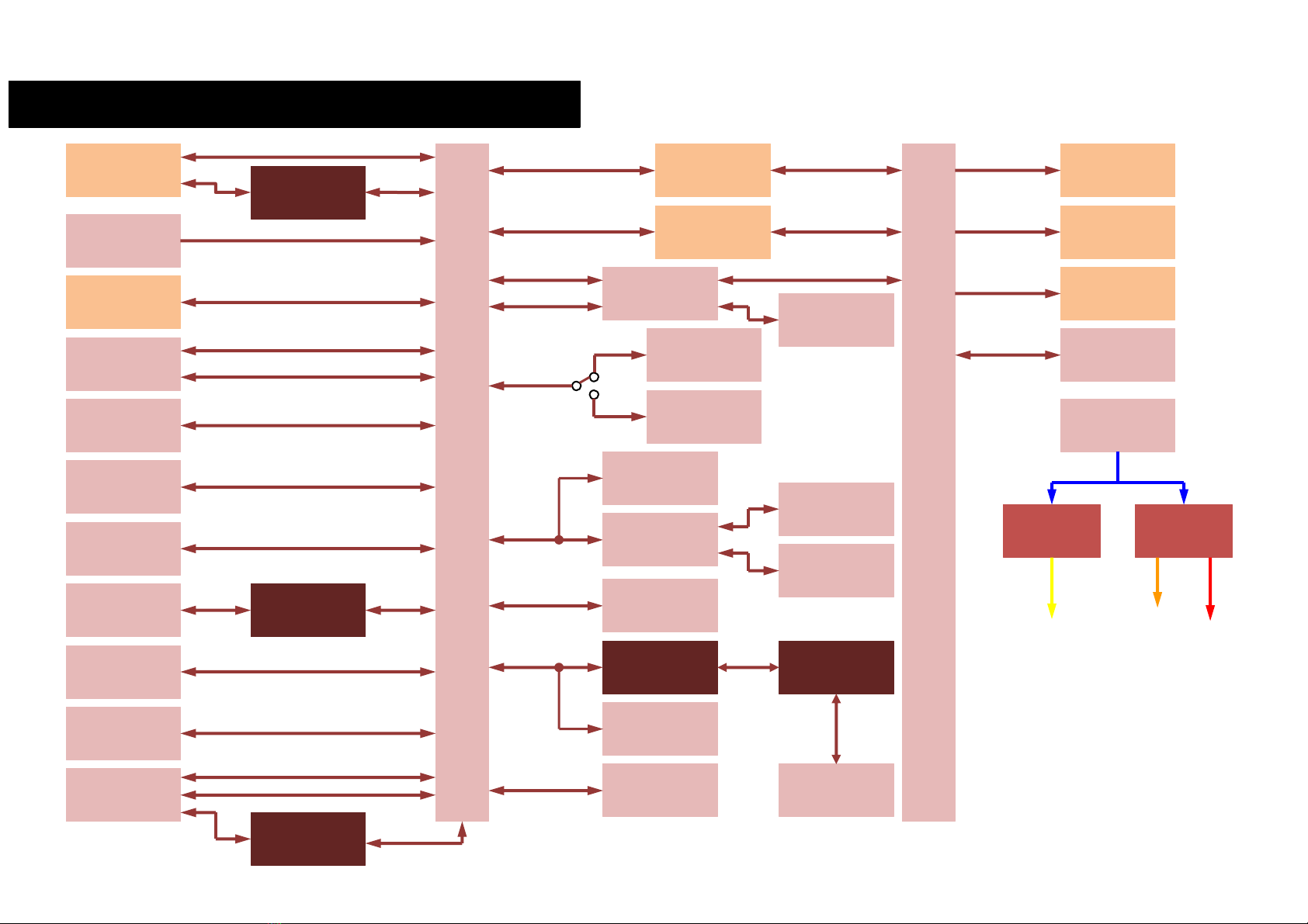
2.5 Block Diagram
Gigabit Ethernet
controller
Battery holder
Dual USB 2.0
Type-A connector
M.2 Socket 1 Key E
2230 Slot
(WiFi + BT)
USB Internal pin
header
FAN Connector
HD Audio Codec
M.2 Socket 2 Key B
2242 / 2260 Slot
(SSD)
S-ATA 7p
connector
USB 3.0 upright
Type-A connector
SuperI/O
M.2 Socket 2 Key B
2242 / 3042 Slot
(WWAN)
μSD Card slot
GPI/O header
LVDS connector
Switch/LED Pin
Header
Serial ports pin
header
DP++ connector
miniDP++
connector #1
miniDP++
connector #2
COM-Express A-B connector
Headphone + Mic
Audio Pin Header
Dual USB 3.0
Type-A connector
Dual RJ-45
Ethernet connector
COM-Express C-D connector
2 x USB SS
1x USB SS
1x USB 2.0
2 x USB 2.0
UIM
1 x PCI-e x1
1 x USB 2.0
SD / GPIO
LVDS /
eDP
LPC Bus
Pwr Rst button
2x UARTs
PCI-e x1
1 x USB 2.0
1 x USB 2.0
2x USB 2.0
VCC_RTC
PCI-e x1
Gigabit Ethernet
FAN Mgmt
HD Audio
DDI #0
DDI #1
DDI #2
2x1 Mega-Fit®
Power connector
SD
GPIO
ACPI
1 x USB SS
S-ATA #0
S-ATA #1
RS-232 / RS-422 /
RS-485
transceivers
Buck DC/DCs
9÷32V
Buck/Boost
DC/DC
3.3V @ 9A
5V @ 9A
12V @ 9A
Feature Pin Header
2x UART
SM Bus
I2C
eDP 40poles
connector
microSIM slot
External EDID flash
socket
SPI Flash Socket
SPI
Display’s voltages +
management
signals connector
Switch
M.2 Socket 3
Key M 2280 Slot
(PCI-e SSD)
PEG x4
RS-232 transceiver
LPC internal
Header

CCOMe-C30
CCOMe-C30 - Rev. First Edition: 1.0 - Last Edition: 1.0 - Author: S.B. - Reviewed by F.B. Copyright © 2019 SECO S.p.A.
20
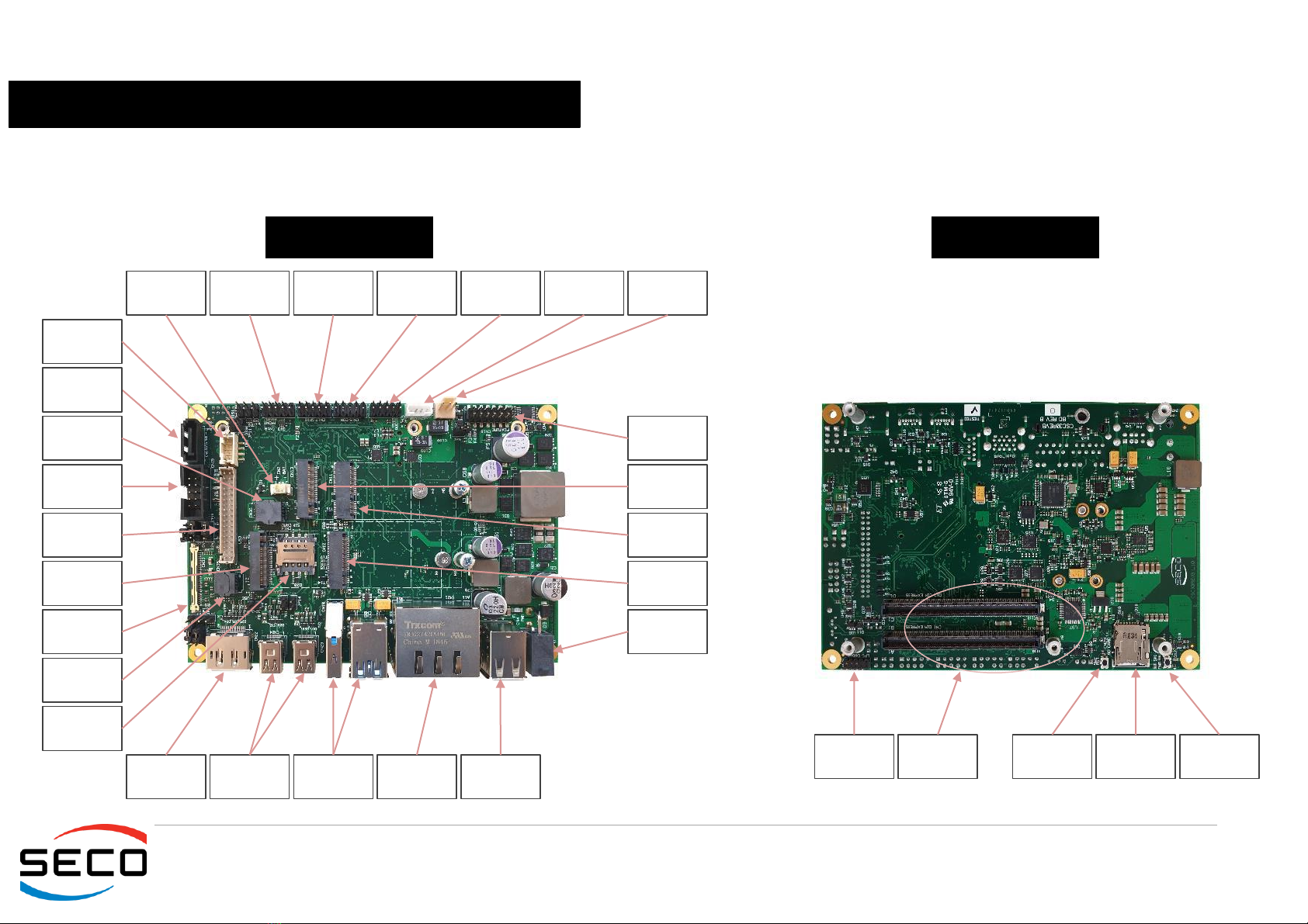
3.1Connectors placement
On CCOMe-C30 carrier board, there are several connectors. Some of them are standard connectors, like Display Port, HDMI, Gigabit Ethernet, USB ports, and are
placed on the same side of the board, so that they can be placed on a panel of a possible enclosure.
In the following picture it is possible to see the position of each connector.
TOP SIDE
BOTTOM SIDE
External
BIOS Flash
socket
Feature
Header
LVDS
external EDID
socket
RTC Battery
connector
Switch/LED
header
GPIO Header
M.2 NVMe
Slot
DP++
connector
miniDP++
connectors
USB 3.0
ports
Dual Gigabit
Ethernet
connector
M.2 SSD
Slot
M.2 WLAN
Slot
microSIM
card slot
LVDS
Connector
Backlight
connector
COM Ports
header Audio
Header
USB internal
connector
SATA
connector
FAN
Connector
USB 2.0
ports #4 #5
eDP
connector
SATA power
connector
M.2 WWAN
Slot
Power
connector
COM
Express
connectors
microSD
card slot
LPC Debug
Header
Reset Switch
SW2 Power On
switch SW1
Table of contents
Other Seco Carrier Board manuals

Seco
Seco Qseven CQ7-D03 User manual

Seco
Seco COM-Express CCOMe-C96 User manual

Seco
Seco Smarc SM-B79 User manual

Seco
Seco Q7-A75-J User manual

Seco
Seco CCHPC-C78-C User manual

Seco
Seco COM-Express CCOMe-C79 User manual

Seco
Seco Smarc CSM-B79 User manual

Seco
Seco Qseven CQ7-D59 User manual

Seco
Seco COM-Express CCOMe-965 User manual

Seco
Seco Qseven CQ7-A30 User manual


