ETAS ES1652.2 User manual

ES1652.2 Carrier Board for Signal Conditioning Circuits
User’s Guide

2
Copyright
The data in this document may not be altered or amended without special noti-
fication from ETAS GmbH. ETAS GmbH undertakes no further obligation in rela-
tion to this document. The software described in it can only be used if the
customer is in possession of a general license agreement or single license. Using
and copying is only allowed in concurrence with the specifications stipulated in
the contract.
Under no circumstances may any part of this document be copied, reproduced,
transmitted, stored in a retrieval system or translated into another language
without the express written permission of ETAS GmbH.
© Copyright 2018 ETAS GmbH, Stuttgart
The names and designations used in this document are trademarks or brands
belonging to the respective owners.
V2.0.0 R04 EN - 7.2018

ES1652.2 Carrier Board for Signal Conditioning Circuits - User’s Guide 3
Contents
ETAS Contents
1 Introduction . . . . . . . . . . . . . . . . . . . . . . . . . . . . . . . . . . . . . . . . . . . . . . . . . . . . . . 5
1.1 Features . . . . . . . . . . . . . . . . . . . . . . . . . . . . . . . . . . . . . . . . . . . . . . . . . . . . 5
1.2 Basic Safety Instructions . . . . . . . . . . . . . . . . . . . . . . . . . . . . . . . . . . . . . . . . 7
1.2.1 Correct Use . . . . . . . . . . . . . . . . . . . . . . . . . . . . . . . . . . . . . . . . . . . 7
1.2.2 Labeling of Safety Instructions . . . . . . . . . . . . . . . . . . . . . . . . . . . . . 7
1.3 RoHS conformity . . . . . . . . . . . . . . . . . . . . . . . . . . . . . . . . . . . . . . . . . . . . . . 7
1.3.1 European Union . . . . . . . . . . . . . . . . . . . . . . . . . . . . . . . . . . . . . . . 7
1.3.2 China . . . . . . . . . . . . . . . . . . . . . . . . . . . . . . . . . . . . . . . . . . . . . . . 7
1.4 CE marking . . . . . . . . . . . . . . . . . . . . . . . . . . . . . . . . . . . . . . . . . . . . . . . . . . 8
1.5 Taking the Product Back and Recycling . . . . . . . . . . . . . . . . . . . . . . . . . . . . . 8
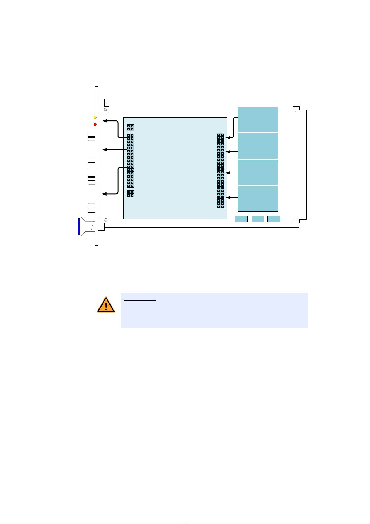
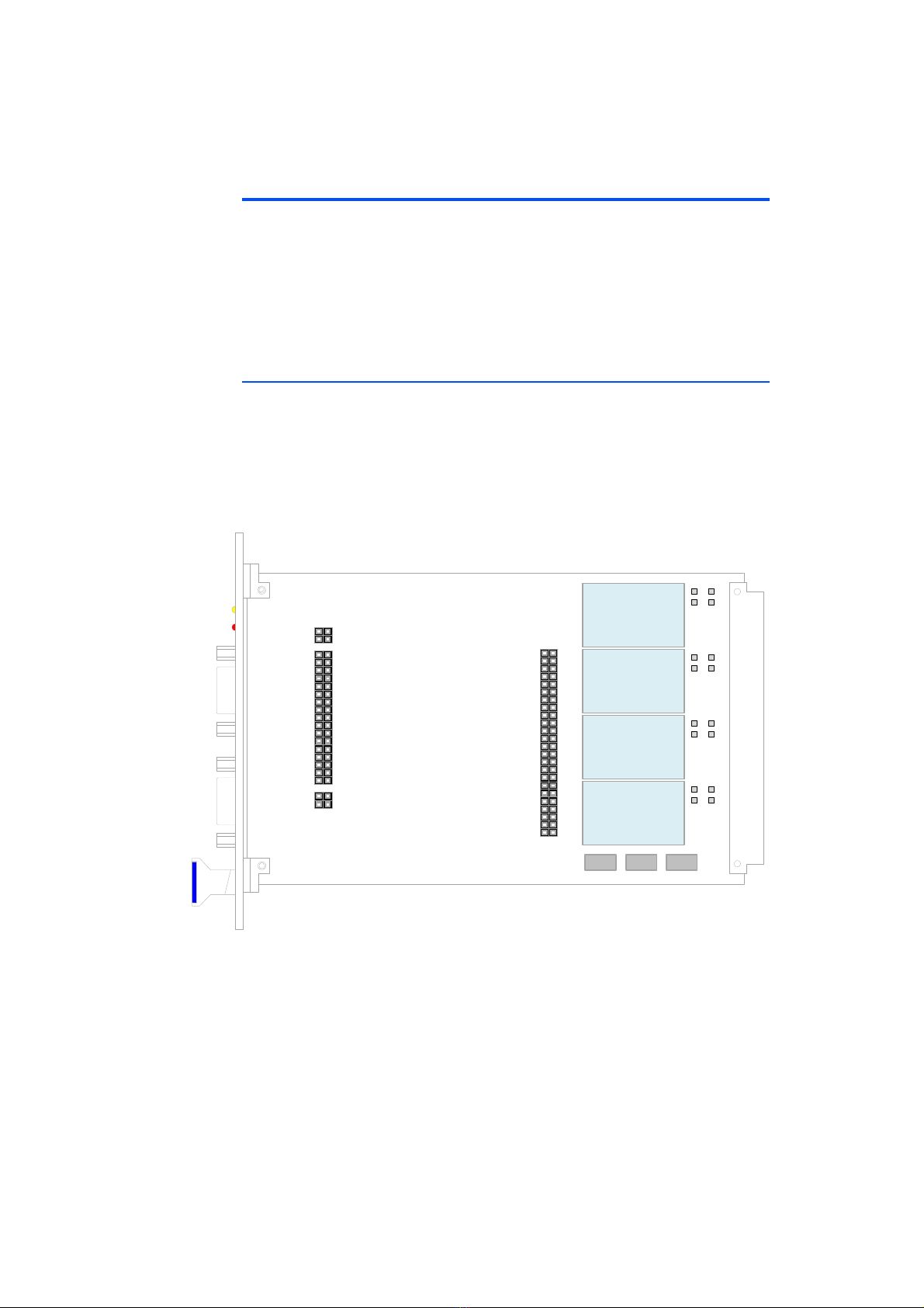
2 Hardware Description . . . . . . . . . . . . . . . . . . . . . . . . . . . . . . . . . . . . . . . . . . . . . . . 9
2.1 Power Supply . . . . . . . . . . . . . . . . . . . . . . . . . . . . . . . . . . . . . . . . . . . . . . . . 9
2.1.1 Configuration of the Input Voltage of the DC/DC Converters . . . . 10
2.2 Fuses . . . . . . . . . . . . . . . . . . . . . . . . . . . . . . . . . . . . . . . . . . . . . . . . . . . . . 11
2.3 Addressing the LEDs on the Front Panel . . . . . . . . . . . . . . . . . . . . . . . . . . . 11
3 Pin Assignment . . . . . . . . . . . . . . . . . . . . . . . . . . . . . . . . . . . . . . . . . . . . . . . . . . . 13
3.1 "CO100" Connector . . . . . . . . . . . . . . . . . . . . . . . . . . . . . . . . . . . . . . . . . 13
3.2 "CO101" Connector . . . . . . . . . . . . . . . . . . . . . . . . . . . . . . . . . . . . . . . . . 14
4 Technical Data . . . . . . . . . . . . . . . . . . . . . . . . . . . . . . . . . . . . . . . . . . . . . . . . . . . 15
4.1 Fulfilled Standards and Norms . . . . . . . . . . . . . . . . . . . . . . . . . . . . . . . . . . . 15
5 ETAS Contact Addresses . . . . . . . . . . . . . . . . . . . . . . . . . . . . . . . . . . . . . . . . . . . . 17
Index . . . . . . . . . . . . . . . . . . . . . . . . . . . . . . . . . . . . . . . . . . . . . . . . . . . . . . . . . . 19

ES1652.2 Carrier Board for Signal Conditioning Circuits - User’s Guide4
Contents ETAS

ES1652.2 Carrier Board for Signal Conditioning Circuits - User’s Guide 5
ETAS Introduction
1 Introduction
This User’s Guide describes the ES1652.2 Carrier Board for Signal Conditioning
Circuits. This chapter contains information on the basic functions and the area of
use of the ES1652.2 Carrier Board for Signal Conditioning Circuits.
1.1 Features
The ES1652.2 Carrier Board for Signal Conditioning Circuits is used to accommo-
date modules for signal conditioning (example: PB1652LAMBDA.1-B Signal Con-
ditioning for Lambda Sensor Simulation).
Fig. 1-1 Front Panel of the ES1652.2 Carrier Board for Signal Conditioning
Circuits
CAUTION!
Some components of the ES1652.2 Carrier Board for Signal Condi-
tioning Circuits can be damaged or destroyed by electrostatic dis-
charge. Leave the board in the transport packaging until it is installed.
The ES1652.2 Carrier Board for Signal Conditioning Circuits must
always be removed from the transport packaging, configured and
installed at a workstation that is protected from electrostatic dis-
charge.

ES1652.2 Carrier Board for Signal Conditioning Circuits - User’s Guide6
Introduction ETAS
The functions of the ES1652.2 Carrier Board for Signal Conditioning Circuits are
shown in the following block diagram:
Fig. 1-2 Block Diagram
The input signals are supplied via the 9-pin "IN 1..9" connector and routed to
the piggyback. From there, they are led back through connector "OUT 1..15" -
once they have been processed. There are also eight LEDs on the front panel
which can be addressed by the piggyback.
Up to four DC/DC converters can be installed on the ES1652.2 Carrier Board to
power the piggyback. These can be supplied with either +5 V or +12 V from the
VMEbus backplane.
There are three fuses on the carrier board that provide protection against volt-
ages from the backplane.
CAUTION!
There is no protective circuit on the ES1652.2 Carrier Board for the
inputs and outputs! If required, this must be ensured by the customer
on the relevant piggyback.
Piggyback
Module
IN 1..9OUT 1..15
DC/DC Converter
DC/DC Converter
DC/DC Converter
DC/DC Converter

ES1652.2 Carrier Board for Signal Conditioning Circuits - User’s Guide 7
ETAS Introduction
1.2 Basic Safety Instructions
Please adhere to the safety instructions in this manuals to avoid injury to yourself
and others as well as damage to the device.
1.2.1 Correct Use
ETAS GmbH cannot be made liable for damage which is caused by incorrect use
and not adhering to the safety instructions.
1.2.2 Labeling of Safety Instructions
The safety instructions contained in this manual are shown with the standard
danger symbol shown below:
The following safety instructions are used. They provide extremely important
information. Please read this information carefully.
1.3 RoHS conformity
1.3.1 European Union
The EU Directive 2002/95/EU limits the use of certain dangerous materials for
electrical and electronic devices (RoHS conformity).
ETAS confirms that the product corresponds to this directive which is applicable
in the European Union.
1.3.2 China
ETAS confirms that the product meets the product-specific applicable guidelines
of the China RoHS (Management Methods for Controlling Pollution Caused by
Electronic Information Products Regulation) applicable in China with the China
RoHS marking affixed to the product or its packaging.
CAUTION!
indicates a low-risk danger which could result in minor or less serious
injury or damage if not avoided.
WARNING!
indicates a possible medium-risk danger which could lead to serious
or even fatal injuries if not avoided.
DANGER!
indicates a high-risk, immediate danger which could lead to serious
or even fatal injuries if not avoided.

ES1652.2 Carrier Board for Signal Conditioning Circuits - User’s Guide8
Introduction ETAS
1.4 CE marking
ETAS confirms that the product meets the product-specific applicable European
Directives with the CE marking affixed to the product or its packaging. The CE
Declaration of Conformity for the product is available upon request.
1.5 Taking the Product Back and Recycling
The European Union has passed a directive called Waste Electrical and Electronic
Equipment, or WEEE for short, to ensure that systems are set up throughout the
EU for the collection, treatment and recycling of electronic waste.
This ensures that the devices are recycled in a resource-saving way representing
no danger to health or the environment.
Fig. 1-3 WEEE-Symbol
The WEEE symbol on the product or its packaging shows that the product must
not be disposed of as residual garbage.
The user is obliged to collect the old devices separately and return them to the
WEEE take-back system for recycling.
The WEEE Directive concerns all ETAS devices but not external cables or batteries.
For more information on the ETAS GmbH Recycling Program, contact the ETAS
sales and service locations (see "ETAS Contact Addresses" on page 17).

ES1652.2 Carrier Board for Signal Conditioning Circuits - User’s Guide 9
ETAS Hardware Description
2 Hardware Description
This chapter contains information on the following topics:
• "Power Supply" on page 9
– "Configuration of the Input Voltage of the DC/DC Converters"
on page 10
• "Fuses" on page 11
• "Addressing the LEDs on the Front Panel" on page 11
2.1 Power Supply
To power the piggybacks, up to four DC/DC converters can be accommodated
on the ES1652.2 Carrier Board for Signal Conditioning Circuits for the purposes
of voltage stabilization and galvanic isolation.
The output voltages DC1 - DC4 of the converters are connected with the con-
nector strip CO101 (see ""CO101" Connector" on page 14) and can thus be
used to power a piggyback. The converters are powered with voltages from the
VMEbus backplane.
Fig. 2-1 Position of the DC/DC Converters on the ES1652.2 Carrier Board
IN 1..9OUT 1..15
IC100
IC101
IC102
IC103
CO100
CO101

ES1652.2 Carrier Board for Signal Conditioning Circuits - User’s Guide10
Hardware Description ETAS
2.1.1 Configuration of the Input Voltage of the DC/DC Converters
It is possible to supply the converters either with +5 V or +12 V from the VMEbus
backplane.
Please observe the correct mapping for the DC/DC converters with respect to the
supply voltages +5 V and +12 V in Tab. 2-1.
The supply voltages are selected using solder straps next to the DC/DC convert-
ers.
Fig. 2-2 Position of the Solder Straps
Mapping of Supply Voltage and DC/DC Converter
Tab. 2-1 DC/DC Converters for the Supply Voltages +5 V and +12 V
Supply Voltage DC/DC Converter (Type)
+5 V TEN3-0522N
+12 V TEN3-1222
IN 1..9OUT 1..15
IC100
IC101
IC102
BR104 VCC5
VDD12
IC102
BR105
IC103
BR106 VCC5
VDD12
IC103
BR107
VCC5
VDD12
IC100
BR100
BR101
VCC5
VDD12
IC101
BR102
BR103

ES1652.2 Carrier Board for Signal Conditioning Circuits - User’s Guide 11
ETAS Hardware Description
2.2 Fuses
There are three fuses on the ES1652.2 Carrier Board that provide protection
against the voltages from the VMEbus backplane.
Fig. 2-3 Position of the Fuses on the ES1652.2 Carrier Board
The fuses are specified as follows:
Tab. 2-2 Fuses
2.3 Addressing the LEDs on the Front Panel
The LEDs are addressed via the "CO100" connector (see ""CO100" Connector"
on page 13).
The LEDs require around 10 mA to light up and have dropping resistors of 825 Ω
for operating with 5 V. If the LEDs are operated at another voltage, appropriate
dropping resistors must be connected in series on the relevant module.
Fuse Type Specification Safeguarding
(Backplane Connector)
FU100 NANO2® Slo-Blo®
Fuse 452/454 Series
T 2 A VCC5
(A32/B32/C32)
FU101 NANO2® Slo-Blo®
Fuse 452/454 Series
T 1 A VDD12
(C31)
FU102 NANO2® Slo-Blo®
Fuse 452/454 Series
T750mA VSS12
(A31)
IN 1..9OUT 1..15
IC100
IC101
IC102
IC103
CO100
CO101
FU100FU101FU102

ES1652.2 Carrier Board for Signal Conditioning Circuits - User’s Guide12
Hardware Description ETAS

ES1652.2 Carrier Board for Signal Conditioning Circuits - User’s Guide 13
ETAS Pin Assignment
3 Pin Assignment
3.1 "CO100" Connector
Tab. 3-1 Connections from "CO100" to LEDs, "IN 1..9" and "OUT 1..15"
CO100 LEDs
1LEDK8
2LEDK7
3LEDK6
4LEDK5
5LEDK4
6LEDK3
7LEDK2
8LEDK1
9LEDA
CO100 D-SUB 9
10 Pin 9: "IN 9"
11 Pin 8: "IN 8"
12 Pin 7: "IN 7"
13 Pin 6: "IN 6"
14 Pin 5: "IN 5"
15 Pin 4: "IN 4"
16 Pin 3: "IN 3"
17 Pin 2: "IN 2"
18 Pin 1: "IN 1"
19 n.c.
CO100 D-SUB 15
20 Pin 15: "OUT 15"
21 Pin 14: "OUT 14"
22 Pin 13: "OUT 13"
23 Pin 12: "OUT 12"
24 Pin 11: "OUT 11"
25 Pin 10: "OUT 10"
26 Pin 9: "OUT 9"
27 Pin 8: "OUT 8"
28 Pin 7: "OUT 7"
29 Pin 6: "OUT 6"
30 Pin 5: "OUT 5"
31 Pin 4: "OUT 4"
32 Pin 3: "OUT 3"
33 Pin 2: "OUT 2"
34 Pin 1: "OUT 1"
4
6
8
10
18
2
12
14
16
22
24
26
20
30
28
32
34
3
5
7
9
17
1
11
13
15
21
23
25
19
29
27
31
33
1
5
234
678
54321
9876
54321
98 7610
15 14 13 12 10

ES1652.2 Carrier Board for Signal Conditioning Circuits - User’s Guide14
Pin Assignment ETAS
3.2 "CO101" Connector
Tab. 3-2 Pin Assignment of Connector "CO101"
Signal CO101 Signal
DC1 VDD 2 1 DC1 GND
DC1 VSS 4 3 DC1 GND
DC2 VDD 6 5 DC2 GND
DC2 VSS 8 7 DC2 GND
DC3 VDD 10 9 DC3 GND
DC3 VSS 12 11 DC3 GND
DC4 VDD 14 13 DC4 GND
DC4 VSS 16 15 DC4 GND
Reserved 18 17 n.c.
Reserved 20 19 Reserved
/SYSRESET 22 21 Reserved
VSS12 * 24 23 Ground *
VDD12 * 26 25 Ground *
VDD12 * 28 27 Ground *
VCC5 * 30 29 Ground *
VCC5 * 32 31 Ground *
VCC5 * 34 33 Ground *
Reserved 36 35 Reserved
Reserved 38 37 Ground *
Reserved 40 39 Reserved
Reserved 42 41 Reserved
Reserved 44 43 Reserved
Reserved 46 45 Reserved
Ground* 48 47 Ground *
* from the VMEbus backplane
3
5
7
9
17
1
11
13
15
21
23
25
19
29
27
31
33
35
37
39
41
43
45
47
4
6
8
10
18
2
12
14
16
22
24
26
20
30
28
32
34
36
38
40
42
44
46
48

ES1652.2 Carrier Board for Signal Conditioning Circuits - User’s Guide 15
ETAS Technical Data
4 Technical Data
Voltages, Currents and Power Consumption
Environmental Conditions
Physical Dimensions
4.1 Fulfilled Standards and Norms
The ES1652.2 Carrier Board for Signal Conditioning Circuits complies with the
following standards and norms:
Maximum voltage at inputs and outputs 60 V
Max. current per individual contact of the input/output connectors 1 A
Maximum sum current over input/output connectors 5 A
Maximum permissible power consumption per DC/DC converter 3 W
Maximum permissible power consumption from VMEbus backplane 10 W
Operating temperature +5 °C to +50 °C (+41 °F to +122 °F)
Relative humidity 0 to 95% (non-condensing)
Storage temperature +5 °C to +85 °C (+41 °F to +185 °F)
Relative humidity 0 to 95% (non-condensing)
Height 3 U
Width 4 HP
Norm Test
EN 61326-1 Electrical equipment for measurement, control and
laboratory use – EMC requirements
EN 61000-6-2 Immunity (industrial environments)
EN 61000-6-3 Emission standard (residential, commercial and
light-industrial environments)
WARNING!
The device confirms only with radio disturbances class A (only for industrial
environment). This can cause radio disturbances in residential, commercial
and light industry environment. In such a case the operator has to consider
additional measures for shielding to avoid disturbances.

ES1652.2 Carrier Board for Signal Conditioning Circuits - User’s Guide16
Technical Data ETAS

ES1652.2 Carrier Board for Signal Conditioning Circuits - User’s Guide 17
ETAS ETAS Contact Addresses
5 ETAS Contact Addresses
ETAS HQ
ETAS GmbH
ETAS Subsidiaries and Technical Support
For details of your local sales office as well as your local technical support team
and product hotlines, take a look at the ETAS website:
Borsigstraße 24 Phone: +49 711 3423-0
70469 Stuttgart Fax: +49 711 3423-2106
Germany WWW: www.etas.com
ETAS subsidiaries WWW: www.etas.com/en/contact.php
ETAS technical support WWW: www.etas.com/en/hotlines.php

ES1652.2 Carrier Board for Signal Conditioning Circuits - User’s Guide18
ETAS Contact Addresses ETAS

ES1652.2 Carrier Board for Signal Conditioning Circuits - User’s Guide 19
ETAS Index
Index
B
Block diagram 6
C
CE Declaration of Conformity 8
Connector
CO100 13
CO101 14
IN 1..9 13
OUT 1..15 13
D
DC/DC converter
configuration of the input voltage
10
E
ETAS Contact Addresses 17
F
Features 5
Fuses 11
L
LEDs on the front panel
addressing 11
P
Pin assignment 13
Power supply 9
Product Back 8
R
Recycling 8
RoHS conformity
China 7
European Union 7
S
Safety instructions, basic 7
Safety instructions, labeling 7
Standards and norms 15
U
Use, correct 7
W
Waste Electrical and Electronic Equip-
ment 8
WEEE take-back system 8

ES1652.2 Carrier Board for Signal Conditioning Circuits - User’s Guide20
Index ETAS
Table of contents
Other ETAS Carrier Board manuals