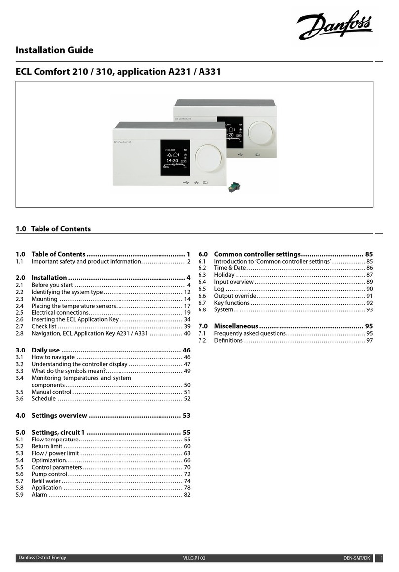
SECOLink PAS8 Series User manual

Short wiring manual –basic information
Control Panels PAS8xxControl Panels PAS8xx
Intruder alarm system
SAFETY WARNINGS
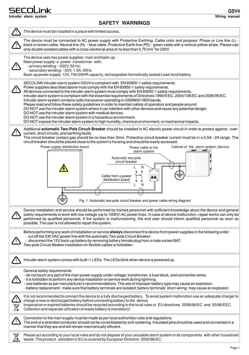
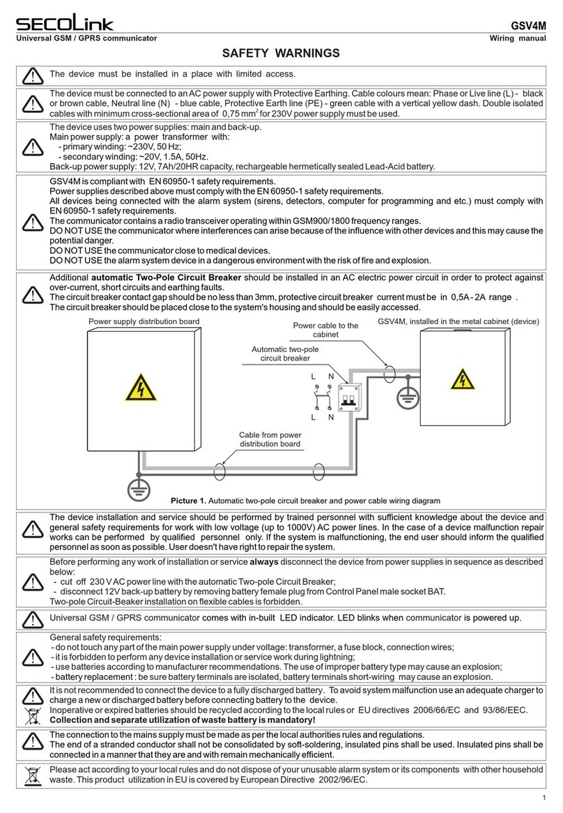
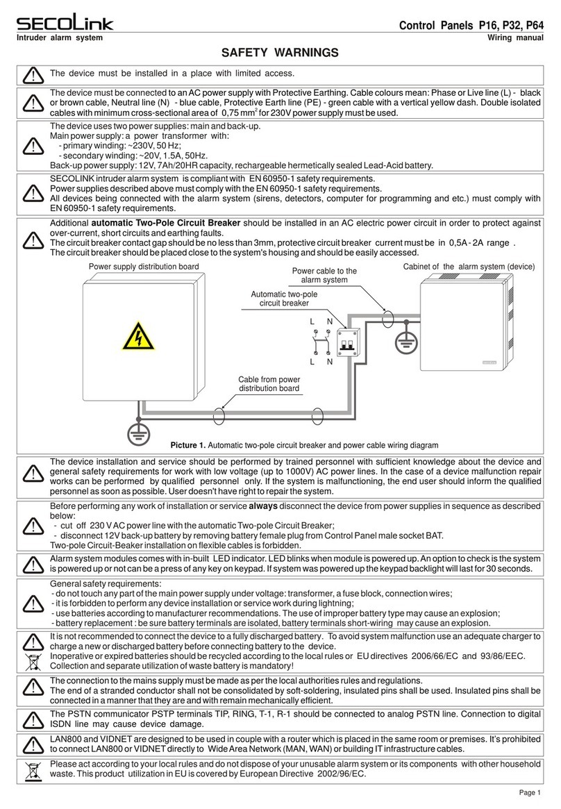
The device must be installed in a place with limited access.
Please act according to your local rules and do not dispose of your old product with normal household
waste. The product is covered by European Directive 2002/96/EC.
The device must be connected –
––
to an AC power supply with Protective Earthing: Phase or Live line (L) black or brown
cable, Neutral line (N) blue cable, Protective Earth line (PE) green cable with a vertical yellow dash. Double
2
isolated cables with minimum cross-sectional area of 0,75 mm for 230V power supply must be used.
The device uses two power supplies: main and back-up.
–
–
2V, 7Ah/20HR capacity, rechargeable hermetically sealed Lead-Acid battery.
Main power supply: a power transformer with:
primary winding: ~230V, 50 Hz;
secondary winding: ~20V, 1.5A, 50Hz.
Back-up power supply: 1
SecoLink intruder alarm system is compliant with the safety requirements of EN 60950-1:2003.
All the above described power supplies linked to the system must comply with the EN 60950-1:2003 safety
requirements.
Additional automatic Two-Pole Circuit Breaker should be installed in anAC electric power circuit in order to prevent
over-current and short circuits.
The circuit breaker contact gap should be no less than 3mm.
The circuit breaker should be placed close to the system's housing and should be easily accessed.
Before performing any work of installation or service ALWAYS disconnect the device from power supplies in
sequence as described below:
- cut off 230 VAC power line with the automatic Two-pole Circuit Breaker;
- disconnect 12V back-up battery by removing battery female plug from Control Panel male socket BAT.
Two-pole Circuit-Beaker installation on flexible cables is forbidden.
General safety requirements:
– do not touch any part of the main power supply under voltage: transformer, a fuse block, connection wires;
– it is forbidden to perform any device installation or service work during lightning;
– use batteries according to manufacturer recommendations. The use of improper battery type may cause an
explosion;
- battery replacement : be sure battery terminals are isolated, battery terminals short-wiring may cause an explosion.
It is not recommended to connect the device to a fully discharged battery. To avoid a malfunction of system use an
adequate charger to charge a new or discharged battery before connecting battery with a device.
Inoperative or expired batteries should be recycled according to the local rules or EU directives 2006/66/EC and
93/86/EEC.
Waste battery collection and returning for utilization separate from household waste is mandatory!
Power supply distribution board Housing of the Alarm System (device)
Automatic Two-pole
Circuir Breaker
L N
NL
Cable from power
distribution board
AC power cable to the
Alarm System
The Control Panel Terminals TIP, RING, T-1, R-1 should be connected to analog PSTN line. Connection to digital
ISDN line may cause the device damage.
Page 1
The device wiring and service should be performed by trained personnel with sufficient knowledge about the device
and general safety requirements for work with low voltage (up to 1000V) AC power lines. In the case of a device
malfunction repair works can be performed by qualified personnel only.

Housing grounding
place
Washer
Bolt
Washer
Nut
Nut
Protective Earth
wire PE
Analog PSTN line
Washer
One 12V 7Ah rechargeable battery is
necessary for correct Control Panel
PAS8xx operation. The battery is used
as back-up power supply in case of the
AC power supply loss.
The battery is used as extra power
supply in case of a temporary load
increase (the siren or the radio
transmitter is ON).
Power supply
distribution board
AC power transformer:
Primary winding: 230V AC 50Hz
Secondary winding: 20V AC 50Hz
~
~
12V battery
7Ah/20HR Black
Red
Serial port SERIAL (see "Module wiring")
Wiring diagrams
10kW
Siren without battery
Siren wirh battery +12V
COM
S
+12V
COM
If a high level is not enough for siren control, it is necessary to
connect a 3-15 kOhm resistor between terminals +BELL and -PGM.
Note: In the template output
+BELL is set for wiring the
siren without a battery. If you
wish to wire a siren with a
battery it is necessary to
change the +BELL (00_1
PGM) definition to "Power
supply" setting.
Zones (see "Zone wiring")
X1
BAT
3.15A
PAS808
PAS808M
PAS808R
PAS816
PAS832
Live
wire
L
Neutral
wire
N
Protective
Earth wire
PE Fuse
250mA
Secolink security systems are supplied to
customers with a pre-installed template in the
keypad memory. The template data has been
transferred to registered system modules during a
system start up ("First start"). The template
includes 1 partition and 8 zones. Zone Z1 is used
for wiring of the magnetic door contact that
monitors the opening/closing of the door. Zone Z2
is intended for an entry/exit path motion sensor
wiring, zones Z3, Z4 are used for wiring of interior
motion sensors, zone Z5 is intended for smoke
detector wiring (the smoke detector must be
powered from the PGM output +PGM). Zone Z6 is
used for tamper switch wiring. Turn OFF the
tamper monitoring if you wish to use zone Z6 for
other purposes. In the template the keypad zones
corresponds to the first zones of control panel on
operation. The programable outputs:
+BELL is used for wiring a siren without battery
(00_1 PGM);
-PGM – for control a siren with battery (00_2 PGM);
+PGM is used for smoke detector powering (00_3
PGM).
Template
Setting:
Default PIN codes
Default service PIN 0000
Default user 01 PIN 0001
Default user 02 PIN 0002
...
Default user 31 PIN 0031
System Setup:
Definition
PGM Outputs
Power Supply
O01
Note: In the template output +PGM (00_3 PGM) is
set for the smoke detector powering (see page
5 "Wiring samples").
AC1 AC2 +BELL COM -PGM +PGM COM CLK DAT +AUX Z1 COM Z2 +AUX Z3 COM Z4 +AUX Z5 COM Z6 +AUX Z7 COM Z8
TIP RING T-1 R-1
DAT
+AUX
Z1
COM
Z2
+AUX
Z3
Z4
+AUX
Z5
COM
Z6
+AUX
Z7
COM
Z8
CLK
COM
-PGM
COM
+BELL
+PGM
AC2
AC1
Maximum permissible long term load of the power supply:
Maximum permissible load of the +AUX output (switching "+"):
Maximum permissible battery charging current:
0,7 A
+0,8 A
0,4 A
Operational maximum ratings of control panel PAS8xx
Maximum permissible load of the +BELL output (switching "+"):
Maximum permissible load of the -PGM output (switching "-"):
Maximum permissible load of the +PGM output (switching "+"):
+0,8 A
-0,05 A
+0,8 A
Battery is disconnected when voltage is less than: 9,5 V
(I + I + I 0,7 A )
+AUX +BELL +PGM
R-1
T-1
RING
TIP
COM
+BELL
COM
+BELL
COM
-PGM
+PGM
DAT
+12V CLKCOM DAT
COM
DAT
+12V
CLK
CLK
COM
+AUX
Module
PAS8xx board
Plastic stud
Cabinet wall
Control panel and modules have to be fastened in
the Alarm System housing (CAS8, CAS8M) using
plastic studs. The module mounting holes should
correspond to housing rear wall apertures. Do not
forget to fix the plastic studs in the apertures before
fastening the housing on a wall.
Z6
AUX
Z7
COM
Z8
Note: The data line (CLK, DAT) length (the distance between
control panel and module) must not exceed 300 metres. It is
recommended to use a 6-wire or 8-wire cable for the module
wiring. It is advised to use the free wire pairs for the module
power supply, when the modules are on considerable
distance from PAS8xx.
Service Mode:
System setup
System setup:
Modules:
Use Tamper
Settings
No
M00
Turning OFF the Tamper:
Housing tamper
switch
Tamper function
PAS8xx Module
A
B
C
Voltage is measured only in a point A. The voltages on terminals of connected
detectors B, C should be measured using a voltmeter.
It is possible to find out the voltage between module terminals +12V ir COM during
the voltage test ("Main Menu/Test/Voltage Test"). The SECOLink module supply
voltage should be in the range of 9-14 V, but for module RCM800(wl) it should
exceed 10,5 V if the Relay PGMs are used.
COM Z6 +AUX Z7 COM Z8
COM
CAS8, CAS8M
PAS8xx
PAS8xx Module 1
Module 2
75 m
Module 3
150 m
75 m
(375 m)
(300 m)
(150 m)
150 m
Modules
Short wiring manual –basic information
Control Panels PAS8xxControl Panels PAS8xx
Intruder alarm system
Service Mode:
System Setup
Note: In the template PAS8xx zone Z6 is used for wiring the tamper switch of the
housing. If the housing door is opened the system will indicate a trouble or will
raise an alarm if the system is armed. If the Tamper function is not necessary it is
possible to turn it OFF and use Z6 as a normal zone.
9,5 V
Page 2

Two-color LED
Buzzer
RID820
Raudonas
Juodas
Þalias
Geltonas
Wiring of modules
X1
BAT
3.15A
PAS808
PAS808M
PAS808R
PAS816
PAS832
TIP RING T-1 R-1
R-1
T-1
RING
TIP
AC1 AC2 +BELL COM -PGM +PGM COM CLK DAT +AUX Z1 COM Z2 +AUX Z3 COM Z4 +AUX Z5 COM Z6 +AUX Z7 COM Z8AC1
AC1
AC2
+BELL
COM
-PGM
+PGM
COM
CLK
DAT
+AUX
Z1
COM
Z2
+AUX
Z3
COM
Z4
+AUX
Z5
COM
Z6
+AUX
Z7
COM
Z8
KM20B, KM20BT
KM24, KM24A
Z2
COM
+12V
Z1
+12V
COM
CLK
DAT
Z2/PGM
Z1
+12V
COM
CLK
DAT
DAT
CLK
COM
+AUX
CLK DAT
+12V COM
+12V Z1
Z2 COM
+12V
OC1
COM
OC2
CLK
K10
K20
DAT
K1
K2
TMP
K1C
K2C
DAT
COM
CLK
+12V
RCM800, RCM800WL EXM800
Z1 COM Z2K7 Z3K6 Z4K5 Z5K4 Z6K3 Z7K2 Z8K1
COM COM COM +AUX
+AUX COM CLK DAT
Z1
COM
Z2/K7
Z3/K6
COM
Z4/K5
Z5/K4
COM
Z6/K3
Z7/K2
COM
Z8/K1
+AUX
+AUX
COM
CLK
DAT
+AUX
COM
CLK
DAT
OPENOPEN
LOCKLOCK
GSV2M, GSV2C,
GSV2A
LAN cable
RING TIP
+12V COM CLK DAT
LAN800
RING
TIP
+12V
COM
CLK
DAT
+12V
COM
CLK
DAT
TMP
NO
K
NC
+12V COM CLK DAT TMP NO K NC
+AUX
COM
CLK
DAT
+AUX
COM
CLK
DAT
433,92 MHz
(only EXT216) 868 MHz
EXT116,
EXT216
+12V
COM
CLK
DAT
+AUX
COM
CLK
DAT
+12V
COM
CLK
DAT
PROX8
+AUX
COM
CLK
DAT
+AUX
COM
CLK
DAT
COM
CLK
DAT
+12V
Z1
PGM
Z2
+12V COM CLK DAT
+AUX
COM
CLK
DAT
For use of this wire for wiring of modules it is necessary to see
the description of the module and the software version number.
Page 3
Short wiring manual –basic information
Control Panels PAS8xxControl Panels PAS8xx
Intruder alarm system

Wiring of modules in large or high security level systems
Power supply
distribution board
AC power transformer:
Primary winding: 230V AC 50Hz
Secondary winding: 20V AC 50Hz
~
~
12V battery
7Ah/20HR
Black
Red
Live
wire
L
Neutral
wire
N
Protective
Earth wire
PE Fuse
250mA
X1
BAT
OVL
CHG
LOW
MOD
PWR15
PWR20
MOD - indicates a module address in system.
LOW - indicates low module battery status.
CHG - indicates battery charging status.
OVL - indicates an overload of +BELL or + AUX.
KRbus
PWR20 – additional power supply with bus
repeater and three PGMs
Disconnect the system from 230V AC
power supply, pull out the battery cable
plug from the BAT socket. Make a short
circuit between the PGM output and
zone Z1 (see diagram) using a wire.
Power up the system with battery is
unpluged. As these actions has been
done it is possible to enter the service
mode using restored default service
PIN = “0000".
Default service PIN restoring
System start-up with no AC 230V power
X1
BAT
3.15A
+BELLCOM CLK-I DAT-I +AUX COM CLK-ODAT-O
-PGM1-PGM2-TMPR
AC ~ AC
Power supply distribution board AC power transformer:
Primary winding: 230V AC 50Hz
Secondary winding: 20V AC 50H
~
~
Live
wire
L
Neutral
wire
N
Protective
Earth wire
PE Fuse
250mA
AC1 AC2 +BELL COM -PGM +PGM COM CLK DAT +AUX Z1 COM Z2
AC
AC
-PGM1
-PGM2
-TMPR
+BELL
COM
CLK-I
DAT-I
+AUX
COM
CLK-O
DAT-O
AC1
AC2
+BELL
COM
-PGM
+PGM
COM
CLK
DAT
+AUX
Z1
COM
Z2
DAT from PAS8xx
CLK from PAS8xx
COM from PAS8xx
3.15A
X1
BAT
AC1 AC2 +BELL COM -PGM
AC1
AC2
+BELL
COM
-PGM
12V battery
7Ah/20HR
Black
Red
Maximum permissible long term load of the power supply:
Maximum permissible load of the +AUX output (switching "+"):
Maximum permissible battery charging current:
1 A
+1 A
0,4 A
Operational maximum ratings of PWR15
Maximum permissible load of the +BELL output (switching "+"):
Maximum permissible load of the -PGM1 output (switching "+"):
Maximum permissible load of the -PGM2 output (switching "+"):
+2 A
-0,05 A
-0,05 A
Battery is disconnected when voltage is less than: 9,5 V
(I + I 1 A )
+AUX +BELL
Wire
KM20B, KM20BT
Z2
COM
+12V
Z1
+12V
COM
CLK
DAT
DAT
CLK
COM
+AUX
CLK DAT
+12V COM
+12V Z1
Z2 COM
Additional information
Keypad attachment
Keypad
Safe wiring of outdoor siren
Page 4
Short wiring manual –basic information
Control Panels PAS8xxControl Panels PAS8xx
Intruder alarm system
Modules PWR15, PWR20 are powered
by a separate power transformer, a
separate rechargeable 12V 7Ah battery
should be wired. If alarm system includes
PWR15, PWR20 it is recommended to wire
an outdoor siren to the PWR15, PWR20
terminals +BELL, -PGM1 (-PGM2) and
COM by the way as it is shown on page 2.
Thus at trouble of the battery of an outdoor
siren or short circuit in the power wires of an
outdoor siren the increased current will
have no influence on the control panel
operation. The repetition of bus is a perfect solution when the criminals
are trying to neutralize the security system by shorting the
keypad wiring located near an entry door or the PROX8
wiring with a hope it will disturb the operation of the system.
In this case only the modules wired to the bus repeated by
PWR20 would stop operate, but the remaining part of the
system would operate, would send a burglary alarm report
and would cause additional difficulties to the intruders.
The terminals CLK, DAT and COM of the control panel
PAS8xx are wired to the terminals CLK-I, DAT-I and COM
of the module PWR20. Re-transmitted bus appears on the
CLK-O and DAT-O terminals. Modules that use the re-
transmitted BUS are powered by PWR20 output +AUX.
For the attachment of keypads use only
self-tapping screws with flat (countersunk)
head (3x30 PH). Make sure that the screw
is screwed completely and the head is
sinked into the wall of the housing. If you
are using other type of screws or if you fail
to screw them fully there is a possibility of
the screw touching the keypad electronics
wich would cause the keypad fail.
Connect 12VAh/20HR battery to the PAS8xx BAT connector. With an
additional wire connect the negative battery pole to the PAS8xx COM
terminal for a short time. The system will start operate however the AC
loss trouble will be indicated.

Wiring of zones
Normally closed
contact
(NC)
+12V +12V
COM COM
NC NOT2 T2COM COMT1 T1
Sensor
Normally closed
contact with one
resistor
(NC/EOL)
+12V +12V
COM COM
Normally closed
contact with two
resistors
(NC/DEOL)
+12V +12V
COM COM
Normally open
contact
(NO)
Normally open contact
with one resistor
(NO/EOL)
Normally open contact
with two resistors
(NO/DEOL)
NCT2 COMT1
1kW
NC NOCOM COMT2 T2T1 T1
1kW1kW1kW1kW1kW
NOCOMT2T1
Wiring of single zones
Wiring of double zones (only PAS832)
+AUX COM Z1 COM
+AUX
COM
Z1
COM
+AUX COM Z1 COM
PAS8xx or module PAS8xx or module PAS8xx or module PAS8xx or module PAS8xx or module PAS8xx or module
+AUX
COM
Z1
COM
+AUX COM Z1 COM
+AUX
COM
Z1
COM
+AUX COM Z1 COM
+AUX
COM
Z1
COM
+AUX COM Z1 COM
+AUX
COM
Z1
COM
+AUX COM Z1 COM
+AUX
COM
Z1
COM
+12V
COM
T1
T2
COM
NC
+12V
COM
T1
T2
COM
NC
+12V
COM
T1
T2
COM
NC
+12V
COM
T1
T2
COM
NO
+12V
COM
T1
T2
COM
NO
+12V
COM
T1
T2
COM
NO
Tamper TamperTamper Tamper Tamper Tamper
Z2
PAS8xx
+AUX
COM
Z2
Sensor
Sensor
Z1
Cable
Cable
+AUX
COM
Sensor
+AUX
COM
Z1
Cable
EXM800
+AUX
COM
Z1
Z2
PAS8xx
+AUX
COM
Z2
Sensor
Sensor
Z1
Cable
Cable
+AUX
COM
Sensor
EXM800
ATTENTION! Sensors must be wired without loops
1kW620W
PAS832
+AUX
COM
Z1
COM
NC*COM
Sensor A
+12V
COM
T1
T2
COM
NC*
Tamper
NC*COM
Sensor B
+12V
COM
T1
T2
COM
NC*
Tamper
300W
+12V COM T2T1 T2T1+12V COM
+AUX COM Z1 COM
Sensor A
Sensor B
* - Sensor contact type may be NC or NO.
PAS832
Correct sensor wiring
Wrong sensor wiring
Sensor Sensor Sensor Sensor Sensor
Wiring samples
Wiring of 4-wire smoke detector
+12V COM NOCOM
Detector
+PGM COM Z5 COM
PAS8xx
+PGM
COM
Z5
COM
+12V
COM
COM
NO
Note: the smoke detectors made by
different manufacturers may have a
different contact layout. For more
detailed information about contact
layout look the documentation
supplied by manufacturer of smoke
detector.
The contacts of smoke detector
3
4
2
6
5
To COM
To zone
To COM
To +PGM
D1
NCNC NONO
Relay
PAS8xx or module
+PGM COM
+PGM
COM
D1
NCNC NONO
Relay
PAS8xx or module
+AUX -PGM
+AUX
-PGM
For relay wiring it is recommended to use the
protective diode which would limit the induced
current appearing during turning OFF the relay.
Wiring of relays
The smoke detectors may be triggered by dust, so in
order to prevent false alarms it is necessary to
execute an trigger re-check. For achievement of this
objective an attribute “Fire verification” has to be
assigned to the system’s fire zone, the smoke
detector has to be powered by PGM output with
definition “Fire Power Supply”and the fire zone has to
be assigned to the corresponding PGM trigger
source. In the template is set that fire zone is the
control panel zone Z5, the +PGM2 output is used for
power supply of smoke detectors.
Operation: In order to check the triggered smoke
detector it’s power supply has to be turned OFF and
turned ON again. The system turns OFF the PGM
output for a time equal to PGM trigger time. When this
time expires the system turns ON the PGM output
again and waits for detector operating status settling
(”Detector settling time”). The system executes the
detector trigger re-check with duration equal to “Fire
verification time”. If during this time the smoke
detector is triggered again the system raises a fire
alarm and sends report, if there are no smoke detector
trigger the system does not alarm.
Page 5
Short wiring manual –basic information
Control Panels PAS8xxControl Panels PAS8xx
Intruder alarm system

Wiring of GSV2 (without monitoring of modules)
X1
BAT
3.15A
PAS808
PAS808M
PAS808R
PAS816
PAS832
TIP RING T-1 R-1
R-1
T-1
RING
TIP
AC1 AC2 +BELL COM -PGM +PGM COM CLK DAT +AUX Z1 COM Z2 +AUX Z3 COM Z4 +AUX Z5 COM Z6 +AUX Z7 COM Z8AC1
AC1
AC2
+BELL
COM
-PGM
+PGM
COM
CLK
DAT
+AUX
Z1
COM
Z2
+AUX
Z3
COM
Z4
+AUX
Z5
COM
Z6
+AUX
Z7
COM
Z8
OPENOPEN
LOCKLOCK
GSV2M, GSV2C
+12V
COM
CLK
DAT
TMP
NO
K
NC
+12V COM CLK DAT TMP NO K NC
DAT
CLK
The such wiring way ensures, that even in case of the short circuit between +AUX and COM the module will be able to execute the its main duty - reporting
to the Central Monitoring station or to the user. If the module is wired under this diagram, the control panel can not execute module monitoring and restore its
normal operation in case of failures.
Wiring of GSV2 (with monitoring of modules)
X1
BAT
3.15A
PAS808
PAS808M
PAS808R
PAS816
PAS832
TIP RING T-1 R-1
R-1
T-1
RING
TIP
AC1 AC2 +BELL COM -PGM +PGM COM CLK DAT +AUX Z1 COM Z2 +AUX Z3 COM Z4 +AUX Z5 COM Z6 +AUX Z7 COM Z8AC1
AC1
AC2
+BELL
COM
-PGM
+PGM
COM
CLK
DAT
+AUX
Z1
COM
Z2
+AUX
Z3
COM
Z4
+AUX
Z5
COM
Z6
+AUX
Z7
COM
Z8
OPENOPEN
LOCKLOCK
GSV2M, GSV2C
+12V
COM
CLK
DAT
TMP
NO
K
NC
+12V COM CLK DAT TMP NO K NC
+AUX
COM
DAT
CLK
The control panel is monitoring the operation of modules constantly. If the operation of module fails and the module gives no response to the control panel
commands, then the control panel turns OFF for a short time the PGM output +AUX that powers the modules in such a way trying to restart the module.
Wiring of compatible transmitter via SERIAL connector
X1
BAT
3.15A
PAS808
PAS808M
PAS808R
PAS816
PAS832
TIP RING T-1 R-1
R-1
T-1
RING
TIP
AC1 AC2 +BELL COM -PGM +PGM COM CLK DAT +AUX Z1 COM Z2 +AUX Z3 COM Z4 +AUX Z5 COM Z6 +AUX Z7 COM Z8AC1
AC1
AC2
+BELL
COM
-PGM
+PGM
COM
CLK
DAT
+AUX
Z1
COM
Z2
+AUX
Z3
COM
Z4
+AUX
Z5
COM
Z6
+AUX
Z7
COM
Z8
COM
+12V
TX-CLK
RX-DAT
+13,8 V
COM
RX-DAT
TX-CLK
Attention!The consumption current
of the transmitter should not exceed
of 3A. The power supply circuit has
no short-circuit protection. In case of
short circuit the PCB damage is
possible.
Transmitter
Short wiring manual –basic information
Control Panels PAS8xxControl Panels PAS8xx
Intruder alarm system
Page 6
This manual suits for next models
5
Table of contents
Other SECOLink Control Panel manuals
Popular Control Panel manuals by other brands
DMP Electronics
DMP Electronics XR150FC Series System user's guide
DUYAR
DUYAR FGE-01 Installation, maintenance and operation guide
Trox Technik
Trox Technik EASYLAB Assembly and operating instructions

ESAB
ESAB Caddy A32 instruction manual

FIBARO
FIBARO SWIPE FGGC-001 user manual

Genesis
Genesis Integrated Security System user manual
