Sectoriel SR 03 PCU Quick guide

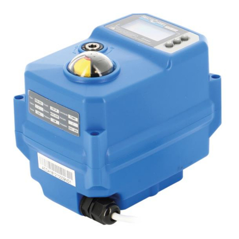
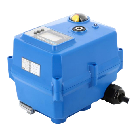
SR 03 PCU ACTUATORS
ASSEMBLING AND MAINTENANCE INSTRUCTIONS
Information given as an indication only, and subject to possible modifications
SECTORIEL S.A.
45, rue du Ruisseau
38290 SAINT QUENTIN-FALLAVIER –FRANCE
Tél : +33 4 74 94 90 70 - Fax : +33 4 74 94 13 95
www.sectoriel.com / Email : secto[email protected]
Pages
1/14
Ref.
IME23070 ENG
Rev.
02
Date
10/2023
SR 03 PCU

SR 03 PCU ACTUATORS
ASSEMBLING AND MAINTENANCE INSTRUCTIONS
Information given as an indication only, and subject to possible modifications
SECTORIEL S.A.
45, rue du Ruisseau
38290 SAINT QUENTIN-FALLAVIER –FRANCE
Tél : +33 4 74 94 90 70 - Fax : +33 4 74 94 13 95
www.sectoriel.com / Email : secto[email protected]
Pages
2/14
Ref.
IME23070 ENG
Rev.
02
Date
10/2023
1. DESCRIPTION
1.1 Electric actuator for motorising 90° turn valves.
1.2 The full features of this device are given in sheet FT23070.
1.3 Before operating this device, read the present instructions carefully.
2. GUARANTEE
2.1 Before any contact with our services, identify the type of actuator.
2.2 SECTORIEL actuators have a 12-month guarantee from the delivery date. Parts recognized
as defective by an assessment at our facility, will be replaced at our expense. Complaints
generated by incorrect use or a modification of the actuator cannot be taken into account.
N°
Désignation
1
Heater
2
Power board
3
Potentiometer
4
Indicator
5
Limit switch
6
Terminal
7
Control board
8
BLDC motor
9
Declutch gear

SR 03 PCU ACTUATORS
ASSEMBLING AND MAINTENANCE INSTRUCTIONS
Information given as an indication only, and subject to possible modifications
SECTORIEL S.A.
45, rue du Ruisseau
38290 SAINT QUENTIN-FALLAVIER –FRANCE
Tél : +33 4 74 94 90 70 - Fax : +33 4 74 94 13 95
www.sectoriel.com / Email : secto[email protected]
Pages
3/14
Ref.
IME23070 ENG
Rev.
02
Date
10/2023
3. VERIFICATIONS AND ACCEPTANCE
3.1 At acceptance, check that:
- the packaging is in good condition.
- the actuator is as ordered.
- the equipment is not damaged.
3.2 It is recommended to install the actuator as soon as accepted and not to leave it unused. If the
equipment has to be stored, it has to be in a dry place protected from weather.
4. PRECAUTIONS FOR OPERATION
4.1 Before installing, make sure that the installation is completely depressurized and brought to
ambient temperature.
4.2 In a zone classified as explosive, install only model SA05X.
Do not install this actuator in a marine environment and do not immerse it.
4.3 The actuator must not be electrically powered during the installation and maintenance of
the valve on the pipework, and of the actuator on the valve.
4.4 Before proceeding to the electrical connection, check the supply voltage of the actuator.
4.5 Do not mount the actuator in series or in parallel with other electrical motors. If need be
use relays.
4.6Do not mount the actuator on valves with higher torque than the nominal torque of the actuator.
4.7 Under normal operation: These motors have to be electrically controlled for opening or closing.
Spring driven return only takes places in case of power supply cut-off.
5. INSTALLATION ET UTILISATION
5.1 Install the actuator on the valve (already done for units assembled in our workshops)
5.2 Perform the electrical wiring as shown in the diagram below.
5.3 Adjust the switch stops (already done for units assembled in our workshops).
5.4 View the valve’s movement using the indicator light on the cover.
5.5 Mounting
Model
A (mm)
SR03
130

SR 03 PCU ACTUATORS
ASSEMBLING AND MAINTENANCE INSTRUCTIONS
Information given as an indication only, and subject to possible modifications
SECTORIEL S.A.
45, rue du Ruisseau
38290 SAINT QUENTIN-FALLAVIER –FRANCE
Tél : +33 4 74 94 90 70 - Fax : +33 4 74 94 13 95
www.sectoriel.com / Email : secto[email protected]
Pages
4/14
Ref.
IME23070 ENG
Rev.
02
Date
10/2023
6. MANUAL INTERVENTION
CAUTION : Before any manual intervention, cut off the power supply, otherwise the SR actuator provided with
an electromagnetic clutch, can be damaged.
6.1 Put the hex wrench into the manual socket and turn to CW.
The lever shaft pops up and manual operation is available.
6.3 Put the lever shaft and turn the wrench to CCW it is switched to auto mode.
6.4 The declutch gear should go down to its original positon to restore the limit setting to factory set and pop
up using the hex wrench when resetting the limit positions.

SR 03 PCU ACTUATORS
ASSEMBLING AND MAINTENANCE INSTRUCTIONS
Information given as an indication only, and subject to possible modifications
SECTORIEL S.A.
45, rue du Ruisseau
38290 SAINT QUENTIN-FALLAVIER –FRANCE
Tél : +33 4 74 94 90 70 - Fax : +33 4 74 94 13 95
www.sectoriel.com / Email : secto[email protected]
Pages
5/14
Ref.
IME23070 ENG
Rev.
02
Date
10/2023
7. STOP ADJUSTMENT
The return spring of the actuator becomes active in case of emergency stop (a power cut, e.g.)
In this case, spring stops have to be adjusted, using stop screws.
The SR actuator is protected when the stops are properly adjusted.
(carry out the adjustment of stops (screws) before adjusting the limit switches).
7.1 Manually place the actuator in the closed position after attaching it on top of the valve.
7.2 If the stops are incorrectly adjusted, the valve will not be in the fully closed position. In this case,
Adjust the stops to reach the fully closed position. Tighten the stops screws once the adjustment performed.
NOTA : Do not touch the adjustment already performed at the facility.
7.3 Adjust the stops in the same way as the stops in the closed position.
CAUTION : When the limit switch reaches the stop, the actuator works normally. Return to the initial position
when the actuator goes into fault.
The actuator works properly if the cams switch the limit switches before the stop plate reaches the screw. If the
actuator does not work properly, adjust the stop screws again.

SR 03 PCU ACTUATORS
ASSEMBLING AND MAINTENANCE INSTRUCTIONS
Information given as an indication only, and subject to possible modifications
SECTORIEL S.A.
45, rue du Ruisseau
38290 SAINT QUENTIN-FALLAVIER –FRANCE
Tél : +33 4 74 94 90 70 - Fax : +33 4 74 94 13 95
www.sectoriel.com / Email : secto[email protected]
Pages
6/14
Ref.
IME23070 ENG
Rev.
02
Date
10/2023
8. SWITCH SETTING
Limit setting when electrical power isn’t supplied.
8.1 Put the hex wrench into the declutch gear and turn to CW. The declutch gear pops and manual operation
is available. The actuator remains the last position during the manual operation without holding the wrench.
Adjust limit cams with the hex wrench after mounting with the valve.
8.2 The declutch gear should go down to its original position to restore the limit setting to factory set and pop
Up using the hex wrench when resetting the limit positions.
Be sure to push the ASCN button to save the setting after limit setting.
Limit setting when electrical power is supplied
8.3 Position the declutch gear to the auto mode before limit setting.
8.4 Push the ZERO and SPAN buttons at the same time and check if the POWER and FAULT lamps turn on.
8.5 Limit setting by ZERO (closing) / SPAN (opening) buttons.
8.6 Push the ZERO and SPAN buttons to change into the auto / manual mode mentioned here is the setting
mode on the BLDC board. In the auto mode : Power lamp (lighting) / fault lamp (flickering)
8.7 Push the declutch gear and turn to CCW to position to the auto mode with the hex wrench after finishing
the setting.
Be sure to push the ASCN button to save the setting after limit setting.

SR 03 PCU ACTUATORS
ASSEMBLING AND MAINTENANCE INSTRUCTIONS
Information given as an indication only, and subject to possible modifications
SECTORIEL S.A.
45, rue du Ruisseau
38290 SAINT QUENTIN-FALLAVIER –FRANCE
Tél : +33 4 74 94 90 70 - Fax : +33 4 74 94 13 95
www.sectoriel.com / Email : secto[email protected]
Pages
7/14
Ref.
IME23070 ENG
Rev.
02
Date
10/2023
Closing/opening limit switch
8.1 The cams ate attached to the drive stem.
8.2 Clockwise rotation = valve closing. The micro-switch closes the actuator.
8.3 Anti-clockwise rotation = valve opening. The micro-switch stops the actuator.
9. CONNEXION
The two inlet cables of the SR actuator are connected using an M20 x 1.5 connection.
9.1 The unused cable inlets must be plugged.
9.2 Standard cable glands and version for shielded cable can be used.
It is recommended to fit a glued (resin) sealing gasket on the actuator’s connections once
the wiring is completed. This is to prevent humidity and water from penetrating inside.
AOLS :
Dry contact open limit switch
ACLS :
Dry contact close limit switch
OLS :
Open limit switch
CLS :
Close limit switch

SR 03 PCU ACTUATORS
ASSEMBLING AND MAINTENANCE INSTRUCTIONS
Information given as an indication only, and subject to possible modifications
SECTORIEL S.A.
45, rue du Ruisseau
38290 SAINT QUENTIN-FALLAVIER –FRANCE
Tél : +33 4 74 94 90 70 - Fax : +33 4 74 94 13 95
www.sectoriel.com / Email : secto[email protected]
Pages
8/14
Ref.
IME23070 ENG
Rev.
02
Date
10/2023
10. ELECTRICAL WIRING
10.1 Separate the cover from the actuator’s body. Unscrew the four bolts.
10.2 Before any electrical connection, check that the electrical diagram provided corresponds to the
rating plate.
10.3 Check that the mains voltage corresponds to the voltage mentioned on the rating plate.
10.4 The SR actuator series has a WAGO terminal box which is easy to wire and is protected against vibrations.
Use an AWG 28-4 standard cable.
10.5 Insert a screwdriver as shown above, press and insert the wire.
10.6 Check that the actuator’s earthing is compliant indoors (body) and outdoors (body).
Use a wire of identical cross-section 4.5 ~ 5 mm² for earthing the SR actuator.
10.7 Each actuator has to be actuated by their own individual relays to prevent the voltage from coming back
and possible damage to other actuators.

SR 03 PCU ACTUATORS
ASSEMBLING AND MAINTENANCE INSTRUCTIONS
Information given as an indication only, and subject to possible modifications
SECTORIEL S.A.
45, rue du Ruisseau
38290 SAINT QUENTIN-FALLAVIER –FRANCE
Tél : +33 4 74 94 90 70 - Fax : +33 4 74 94 13 95
www.sectoriel.com / Email : secto[email protected]
Pages
9/14
Ref.
IME23070 ENG
Rev.
02
Date
10/2023
11. SCHEMA DE CABLAGE
Wiring for 230Vac 50Hz voltage
1
Common
2
Phase
3-6
Manual opening command
4-6
Manual closing command
5-6
Fonctioning 4-20 mA
6
Manual and automatic command
7
Opening auxiliary common
8
Closing auxiliary command
9
Auxiliary common

SR 03 PCU ACTUATORS
ASSEMBLING AND MAINTENANCE INSTRUCTIONS
Information given as an indication only, and subject to possible modifications
SECTORIEL S.A.
45, rue du Ruisseau
38290 SAINT QUENTIN-FALLAVIER –FRANCE
Tél : +33 4 74 94 90 70 - Fax : +33 4 74 94 13 95
www.sectoriel.com / Email : secto[email protected]
Pages
10/14
Ref.
IME23070 ENG
Rev.
02
Date
10/2023
Wiring for 24Vcc voltage
1
Common
2
Phase
3-6
Manual opening command
4-6
Manual closing command
5-6
Fonctioning 4-20 mA
6
Manual and automatic common
7
Opening auxiliary command
8
Closing auxiliary command
9
Auxiliary common

SR 03 PCU ACTUATORS
ASSEMBLING AND MAINTENANCE INSTRUCTIONS
Information given as an indication only, and subject to possible modifications
SECTORIEL S.A.
45, rue du Ruisseau
38290 SAINT QUENTIN-FALLAVIER –FRANCE
Tél : +33 4 74 94 90 70 - Fax : +33 4 74 94 13 95
www.sectoriel.com / Email : secto[email protected]
Pages
11/14
Ref.
IME23070 ENG
Rev.
02
Date
10/2023
12. FAULT DIAGNOSTIC
If the actuator does not work properly, check all mechanisms, and look for alignment problems and electrical
problems. (See table below)
PROBLEM
CAUSE
SOLUTIONS
The manual control does not engage
Blocked worm drive
and stop mechanism
Turn the wheel again from left to right
In manual mode, the actuator does
complete its open or closed cycle
Gear box problem or
broken rings
Disassemble the actuator and replace
the gear boxes, damaged stop screw.
Normal
operation,
remote control
The actuator does
complete its open or
closed cycle
Fault on the limit
switch or on the stop
mechanism
Reset of the limit switch or on the stop
mechanism
The actuator does not
work under remote
control
Power cut
Power cut diagnostic
Disconnected wires
or cut-off circuit
Replace the faulty wires
Damaged motor or
condenser
Replace the motor or the condenser
Too high motor
temperature
Motor cycle stop
Wiring problem
Check the electrical diagram and the
cable connection
Blocked gear boxes
Unblock the gear boxes
When the actuator continues to turn
even after the cams engage
the limit switches
Fault on the limit
switch
Disconnection or cut-
off circuit.
Replace the limit switch. Reconnect
the cut circuit
Phase inversion

SR 03 PCU ACTUATORS
ASSEMBLING AND MAINTENANCE INSTRUCTIONS
Information given as an indication only, and subject to possible modifications
SECTORIEL S.A.
45, rue du Ruisseau
38290 SAINT QUENTIN-FALLAVIER –FRANCE
Tél : +33 4 74 94 90 70 - Fax : +33 4 74 94 13 95
www.sectoriel.com / Email : secto[email protected]
Pages
12/14
Ref.
IME23070 ENG
Rev.
02
Date
10/2023
13. CONTROL BOARD
N°
Désignation
N°
Désignation
1
Do not touch the factory setting
10
Time delay
2
Input setting switch
11
Limit switch connector
3
Auto scan / Span / Zero button
12
Input / Output
4
Speed volume
13
Do not touch the factory setting
5
Manual button
14
Motor connector
6
Dead band
15
Do not touch the factory setting
7
Potentionmeter connector
16
Fail speed setting switch
8
Load volume
17
Control DIP switch
9
Terminal

SR 03 PCU ACTUATORS
ASSEMBLING AND MAINTENANCE INSTRUCTIONS
Information given as an indication only, and subject to possible modifications
SECTORIEL S.A.
45, rue du Ruisseau
38290 SAINT QUENTIN-FALLAVIER –FRANCE
Tél : +33 4 74 94 90 70 - Fax : +33 4 74 94 13 95
www.sectoriel.com / Email : secto[email protected]
Pages
13/14
Ref.
IME23070 ENG
Rev.
02
Date
10/2023
CONTROL DIP SWITCH
1
F - C
Fail close
2
F - O
Fail open
3
AFULL
3.8 ~ 4.3 : Input fully Close
19.7 ~ 20.2 : Input fully open
4
CH1
Discretion setting
5
CH2
Manual setting
6
REV
Reverse action
1 - Fail close :
When there is no input signal, the actuator auto manically turns to a full close positon.
2 - Fail open :
When there is no input signal, the actuator auto manically turns to a full open positon.
3 - AFULL :
- If the input signal is at 3.8 ~ 4.3mA , the actuator turns to a full close position.
- If the input signal is at 19.7 ~ 20.2mA , the actuator turns to a full open position.
4 - CH1 : Optional modulation
- It is used when the user voluntarily changes the input signal.
Example : When setting to 6~18mA Input.
- CH1 ON →Input 6mA and press ZERO button.
- Input 18mA and press SPAN button. →CH1 OFF.
- Input and check if the device operates normally.
5 - CH2 : Optional modulation using manual lever
- If is used when the user controls the actuator using the manual lever.
Example : When controlling using the manual lever.
- CH2 ON →Put the actuator at Full Close.
→Press the ZERO button→Put the actuator at Full Open.
→Press the SPAN button→CH2 OFF.
→Input and check if the device operates normally.
6 - REV :
- It is used when the actuator operates in the inverse direction.
- When REV is on and at 4mA, the actuator turns to a full open position, and to a full close position when at 20mA.

SR 03 PCU ACTUATORS
ASSEMBLING AND MAINTENANCE INSTRUCTIONS
Information given as an indication only, and subject to possible modifications
SECTORIEL S.A.
45, rue du Ruisseau
38290 SAINT QUENTIN-FALLAVIER –FRANCE
Tél : +33 4 74 94 90 70 - Fax : +33 4 74 94 13 95
www.sectoriel.com / Email : secto[email protected]
Pages
14/14
Ref.
IME23070 ENG
Rev.
02
Date
10/2023
DIP SWITCH for INPUT Setting
S/W
Input
1
2
3
4 - 20 mA
ON
OFF
OFF
2 - 10 V
OFF
ON
OFF
0 - 5 V
OFF
OFF
ON
0 - 10 V
OFF
ON
ON
1 - 5 v
OFF
OFF
OFF
Fail Speed Setting
S/W
Fail Speed
1
2
4 sec
OFF
OFF
7 sec
ON
OFF
10 sec
ON
ON
ZERO / SPAN / ASCN Button
ZERO
Close manual control button / Input module button
SPAN
Open manual control button / Input module button
ACSN
AUTO SCAN BUTTON (ACTUATOR automatic control button)
delivered from the factory the resistance value of potentiometer may can be changed if the user
modifies its limit setting.
Please make sure to press the autoscan button for at least 2 seconds before operating proportional control.
Check the input and output are correct. (Standard : In/Ouptut 4 –20 mA)
Actuator SPEED Setting : (Between 10 to 35 secondes)
Table of contents
Other Sectoriel Controllers manuals
Popular Controllers manuals by other brands

Emerson
Emerson Powerdrive F300 Getting started guide
TECSYSTEM
TECSYSTEM NT935-4 instruction manual
MicroART
MicroART Kes DOMINATOR MPPT 200/60 user manual

Uponor
Uponor Smatrix Base PRO X-147 installation manual
GSL
GSL RBC-12 Installation & operating instructions
Johnson Controls
Johnson Controls Metasys NCE25 series installation instructions
Schako
Schako VAQS DS0 Series manual
Banner
Banner A-GAGE MINI-ARRAY MAC Series instruction manual
Ashly
Ashly VCM-88 operating manual
Thermokon
Thermokon SRC-DO jalousie Installation and operating instructions

ELCART
ELCART 42/12800-00 user manual

Warner Electric
Warner Electric CBC-802 Service & installation instructions
